

tube80z
-
Posts
1383 -
Joined
-
Last visited
-
Days Won
25
Content Type
Profiles
Forums
Blogs
Events
Gallery
Downloads
Store
Posts posted by tube80z
-
-
17 hours ago, HuD 91gt said:
On the note for string alignments, how are you guys finding the center of the vehicle? I did a string alignment, based on all wheels being equal width. With adjustable control arms, I figure finding the actual center is crucial.
The strings are a box around the vehicle. You don't really need to be centered but you do need to be perpendicular to the front/rear, which often ends up referencing a body panel or a crossmember. This is a good example of the work involved, https://www.turnology.com/features/easy-accurate-inexpensive-do-it-yourself-vehicle-alignment/. It looks more complicated than it is to do. You can also do the same thing with jack stands and fishing line but that takes a little longer to get setup. There are a number of videos on youtube that show how to do it various ways.
-
The easiest alignment system I've found are strings. If you take some time and make a simple jig the is centered on the car these are easy to setup and use. If you don't need to worry about the car being squared up toe plates where you use two tape measures are also a good choice. But whatever you do will require access to the adjusters. The trickest system I ever saw was from Riley & Scott on a world challenge touring car. They had rods they screwed into receptacles on the frame. The had a laser and a target on the same end and on the opposite end you'd mount a mirror to the their setup wheels, which in this case were a special set of tires that were never used mounted on modified wheels that allow attachment of the mirror. The laser would shoot down the side of the car parallel to the frame and bounce off the mirror and back to the target. Accuracy was claimed at one tenth of a degree according to one of the mechanics I chatted with. He even let me inside the pen for a closer look.
I like to go to the pro races and watch the top teams when they do boring things like basic maintenance. Setup wheels are used a lot and often while sitting on scales. You have much better access to all the adjusters and can do easier brake maintenance, ride heights, and so on. For most of us this would be a shop only item to use.
-
Mine all cracked in the bend. The bolts into the body were still tight and a cursory visual inspection missed it until I pulled the diff and it was plain as day. I mostly had problems with the right side. Another SCCA EP car a friend has had similar handling issues so we looked closely and his plates had been cracked too. Same spot also on the right side.
-
Hi Luigi, it allows the strut another axis of movement that isn't putting bind on the strut insert. If you have stock rubber bushings those probably allow enough movement this doesn't matter. WHen you take apart the rear struts and try to line them back up to go on the upper mount you often see how small changes to the pickup points (toe/camber) make it really hard to get back where it needs to go. The stiffer you make the bushings (poly, rod ends, or sphericals) there's less give needed to follow the path laid out by the upper mounts. There's a lot of good info in the suspension section stickies that discusses in deeper detail.
I'd recommend the brace for any V8 or higher powered street car. Years ago I was sitting in a friends V8 car and he tells me to watch the tire from the side mirror. He proceeds to power brake and I see the rear tires toe out and not a small amount. Even on a lower powered car if you corner really hard I'd expect this isn't helpful. The brace helps to reduce this.
-
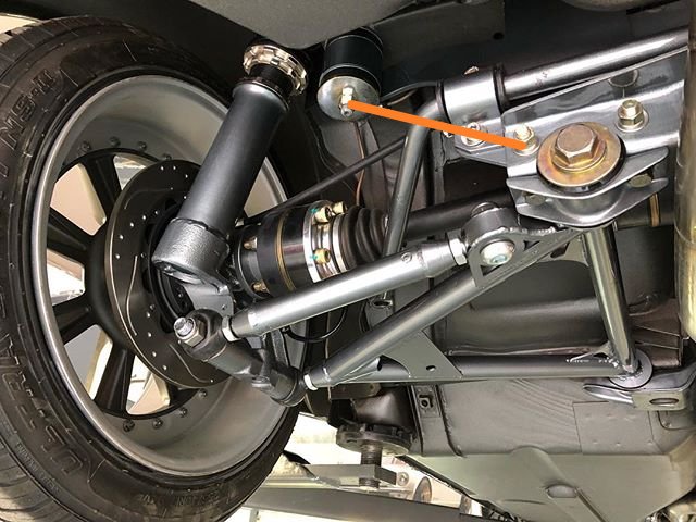
What you want to do for the rear brace is triangulate the lower pickup point with the rear diff stud (orange line). Somewhere I have a picture of this but I can't find it so I used a random image that's in my downloads folder. Not my car or a friends in case you're wondering. Some company in the UK that does rebuilds. Another item to add to your list are toe-link rear arms if you don't already have them. This helps reduce side loads on the strut from alignment changes, which reduces friction.
On my street car I've been looking at a bracket that bolts under the normal spindle pin location that allows a control arm using rod ends to be mounted in double shear. And that's lead to more rat holes and I think I'm leaning towards a fabricating housing that uses nothing Datsun on the outer end to keep costs down. Somewhat similar to the Apex Engineering stuff but different outer mounting and a simple bolt-on hub assembly.

Other easy items to think about.
1. Droop limiters
2. Hanging ARBs from rod ends (lowers friction)
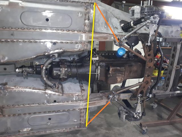
On the front you can do something similar to the yellow and orange lines in the attached image that helps stiffen the suspension mounting points. Rather than bolt things to the TC cup those could be welded and the tubes could mount as plates under the mount. They would stack and be bolted in a sandwich from the bottom. There's a lot of things you could do for engine bay bracing between the strut towers. BMW touring cars had this cool tubular structure that was connected to the strut towers, frame rales, and lower crossmember. It looks like a truss in the engine bay and you could easily hang your motor from it. That would allow you to ditch the normal motor mounts. And if you pick up the bellhousing with mounts you can get rid of the transmission mount. My old race car ran solid mounted this way and it worked really well.
Hope that helps,
Cary
-
Time to move the radiator back to the hole you have there
") I'm sure you've probably already been thinking about that given some of the FB threads. Great to see all the updates. Two things I'd add in case they aren't done. Run a brace from your rear diff mount down to the transverse link, The will help flex that does lead to rear toe changes. Also make sure to inspect those two bits of medal as you have enough tire to crack them. I went through a few sets before adding the braces and never had a problem after. You also need to put bolts into the ebrake bracket that is on the strut. Those little threaded holes can lead to cracking the rear struts if you don't.
I'm sure you've probably already been thinking about that given some of the FB threads. Great to see all the updates. Two things I'd add in case they aren't done. Run a brace from your rear diff mount down to the transverse link, The will help flex that does lead to rear toe changes. Also make sure to inspect those two bits of medal as you have enough tire to crack them. I went through a few sets before adding the braces and never had a problem after. You also need to put bolts into the ebrake bracket that is on the strut. Those little threaded holes can lead to cracking the rear struts if you don't.
-
19 hours ago, grannyknot said:
I suspect you're not finding much on it because the benefits would be minimal I think, you would shift the front/back weight ratio a bit and bring the stick shift back to a more comfortable position, any others?
Actually the benefit is a lot more than you might think, at least for a racing car. I did this with an old car of mine where I set the motor back so the 1st cylinder was on the axle centerline. To do this you need to cut into the firewall. Even moving the engine back to where it almost touches will give you some benefit. It's mostly on how fast the car will change direction. At the time we had a number of cars with identical mods and suspension tuning. The engine setback car was always quicker than the others. The advantage depended on the track design so if there were more changes of direction then it was a bigger gap. The total change for my car was about a half a percent of weight shift to the rear. All the easy things were already moved towards the rear axle.
Once you've move all the easy parts to the back of the car then this can be looked at. Mine was a hack job at best (finishing someone else's project). The motor mounts were done using a flat plate that bolted to the block and allowed the motor mount to be moved a couple of inches. Similar thing done on the engine crossmember mount location. Sorry, photos have long since gone for all this. You do need to be mindful of the oil pump interfering with the front ARB. If you go far enough then you have the rack/crossmember to deal with.
Hope this helps,
Cary
-
For panels that overlapped in my car that needed welding I've used a zinc based weld through primer. My only testing was on some metal I removed from the car, sanded down, sprayed with the weld through primer, and welded up. I left these outside for a couple of years. They had the usual surface rust but nothing major on the weld areas. This isn't much of a test but that's what I've done for overlaps. This will be for a race car that is mostly pampered and will only get wet in occasionally.
What Ironhead describes seems to be how most of the OEMs do it now. You need somewhere for trapped water to go and use a lot of the new seam sealers. Ever take a new car apart and notice how much of that stuff is everywhere? OEMs aren't into spending money on things not needed so that's probably a good thing to follow.
Hope this helps,
Cary
-
I'd recommend more than just the hoop change. Try sitting in the car with a helmet on and you may be hitting the upper halo bars. Those need to be much closer to the roof and often require a couple of bends to make it back to the main hoop. It's your money and this is one of those items you hope to never use but when you never know when you might.
-
23 minutes ago, Ironhead said:
Thanks much for the input.
IJust so I understand....you are talking about mounting the splitter plate on a hinge, and only connecting it to the bumper with some sort of flexible material to block the wind? So the splitter could hinge and move upward with any impact, while the air dam/bumper remain stationary?
You've got it. At first it was for easy on/off when loading/unloading from the trailer. But it worked well when jumpings curbs, various offs, and occasional high angle track entry.
-
I looked through my photos sure I had taken pictures of how we did this on a friends Z. Good thing we didn't bet on it because I would have lost. Every time I do this it's a little different. For just the splitter blade (flat piece, whatever we want to call it) we fabricated what was essentially a outdoor gate latch as the rear pivot and cables connected the to a frame that was mounted to the blade. This allowed you to lift up the front or side if it hit anything but still connect to provide downforce. As we had no idea if this would hold at 150 MPH the frame was very basic and light so if it folded under or came off it wouldn't hurt too much when ran over. To seal to the airdam edging material was going to be added that would mount outside of the bumper cover/airdam. At speed I figured the leakage would be minimal.
My FP car had an airdam and one-piece front end (hood, fenders, grille) and separate airdam with floor (no splitter) that was reinforced with a metal frame. The front end was held down with hood pins that floated on springs so there was some movement allowed. The airdam had a frame behind it and that mounted to a tube that connected to the stock bumper bracket location. I used only the rear bolt hole and it was mounted so it would move up or down and there was a bracket that connected to where the stock hinges were that captured this tube. It was L shaped and the bottom limited the bumper bar from going down and there was an upper limiter on top that used a valve spring to keep some pressure on the tube in the downward location. I don't know if that was needed or not but I had seen a similar setup on a wrecked Ferrari challenge car. The used this for allowing splitter movement. The airdam mount was was tubing that slid over a pin and held in place by a spring clip. I had to be able to take it off to load and tie down the car. Previously it was all connected to the front and and couldn't be removed without much effort.
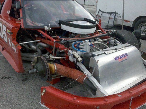
My new car (if it's ever completed) will use a setup like almost all the current Trans-Am and GT1 cars do. That's a seperate frame that hold the splitter, airdam, radiator and front ducting that bolts up to the car. The lower connection is in a cup that allows it move forward to a degree but not rearward. So if ground a corner the body can lift up a limited amount or like loading on a trailer. Since this will replace the core support being able to remove the engine will be easier too. I don't know if the attached image will help or not. Happy to try and draw it out a little better.
Cary

-
When you blot up the tranny make sure to try the clutch fork with your hand. It should have a small amount of play before engaging. If you can move it a half inch or so the release bearing collar is too short. If the lever has no free play and you cannot move it then you probably have top long of a collar. I've screwed this up so many times over the years and finally came to my senses about checking up front. You can measure everything on the bench too and come to the same conclusion but I'd still try it by hand to make sure you don't have some other problem related to the fork.
-
The one recommendation I have is to make the splitter frame movable. In the past I've used either hinge points or support rods that allow movement of the splitter blade upwards. As you have a rigid frame I'd make some provision for it move like this. It will also help if it grounds when you corner. This way you don't unload the corner weight when you really don't want that to happen. Your splitter life will be much longer this way.
-
On 9/18/2019 at 6:00 PM, Twisted46 said:
Here is a clip my wife took, It was lap 1 so not full out but you can see how much the car is leaned over.
https://drive.google.com/open?id=1lHUmts9dnRvONSdJXeCmxB1UYCDN7UCe
Here is a session I recorded in the forester last year
https://drive.google.com/open?id=1_cOSLhnecTk7zxuCZ1SZRiydYeTxENpG
Not trying to be critical, but do you drive the Z like you do the Forrester? I noticed from your Forrester video that you turn the wheel into the corner and hold it for a long time. To be fast in a Z you need to get used to the rear of the car moving around a lot, especially when stock. The trick is to learn what's too much and what's just right. To someone that's never lapped a Z hard before this can feel like the car is going to kill you. You will be unwinding the wheel after turn in much faster in the Z. If you're not then it's like driving around with your foot on the brakes. It also helps to get the entry speed up, which looks lower across most of your data.
Cary
-
 1
1
-
-
If you came here and can't find your posts it's because I have cleaned up this thread to remove recent comments that were making it shed worthy. Feel free to open a new thread around a different topic not related to weight loss. I can move those posts over if needed.
-
On 8/24/2019 at 9:43 AM, Gollum said:
Nice! I'd say that should get cross posted here, but it got moved to the FAQ section, which can't be posted in

I moved it to the FAQ. I tried to keep it here too but couldn't get that to work.
Cary
-
On the false floors make sure they aren't shiny. I had a similar one on my race car and when the sun hit it just right it lit up the windshield to where you could hardly see the road. It doesn't happen all the time but when it does it's not fun. A brushed/matte finish is a nice compromise.
Cary
-
On 8/31/2019 at 5:44 PM, Ben280 said:
Thanks @tube80z! I was hoping you'd reply. Good tips on what to look for. I was thinking that the GTX2/AE arms are close enough to what I'd build that it might be worth it to just get them, and then modify as needed. The T3 stock style arms are a good option, and could likely be beefed up to suit my needs with some more structure and weld in sleeves for sphericals. No gussets on my struts yet, or bearing spacers yet, care to enlighten me on the bearings?! Sounds like a good mod for the off season!
This may seem counter to what we're discussing but be careful getting lower control arms that are too strong. A lot of these are over built and that leads to problems if you ever take a hit. You don't want to have the crossmember and frame rail ripped up from hitting a pothole/curb. On the GT2X arms I'd look at using aluminum rod ends on the crossmember side. I'd do that for the TC rod too. If you're going to modify any of these items then you're not that far from making what you want from scratch.
When it comes to rod ends/sphericals remember to burnish/bed them (see page 22 of http://flipbooksbyadventure.com/RodEndsCatalog/files/assets/common/downloads/publication.pdf). You need to turn the ball (100 RPM or slightly less) to polish the liner (probably wrong terminology) but it helps remove high/low spots and distributes teflon across all surfaces. When you do this you'll feel the rod end suddenly lose torque and you want to remove from the drill or lathe and dunk in ice water. Done right the bearing will also be very easy to move and that reduces friction in the suspension. Very few people do this. Once you get beyond getting the basic setup right almost all of the rest of the small gains come from working on deflection and friction removal. Suspension friction (stiction) reduces mechanical grip. The more of it you get rid of the better.
With regards to bearings I'm not sure of your question. Larger diameter or distance between bearings will make decrease load from cornering/brake forces. I think a good compromise that could be used on the Z would be based on the NASCAR 5x5 hub setup. The bearings for these look almost twice the size as a Datsun bearing. You can get alloy or steel hubs, brake hats, spindles and bearing spacers for these fairly cheap. Download the Howe Racing catalog and see all the options. REM finished or ceramic bearings will help with friction and the ceramics can withstand huge loads and roll with minimal friction. They would be a last step just the same as replacing all the turning/moving parts with Ti fasteners to save weight.
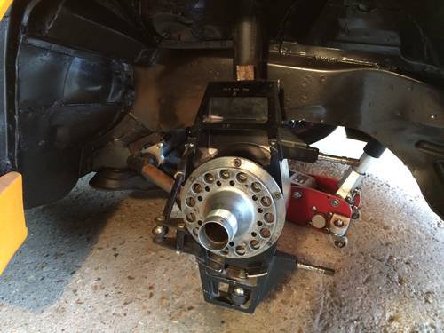
I've attached an example upright from a 2001 BTCC Peugeot 406. Notice the large bearings and how everything is mounted in double shear. If you fab a new upright this is a good example to follow. Just a bit of racing trivia, I asked a mechanic working on a historic BTCC BMW at a historic event where the large bearings came from. He told me they used helicopter main rotor bearings for most of the uprights. Now these are available from race bearing suppliers. The BMW must have had 6 inch diameter bearings. Pretty cool stuff.
-
Ben, you probably won't get much help as I don't think anyone is using these parts in anger as you are. The GT2X arms T3 has look to be similar to AE's arms. To be truthful you'd be better off with a spherical bearing than a ball joint. This is because you use spacers are much easier to put back in the same position than a tapered shank. The stock style arms they sell are probably stiffer in bending under breaking then either the GT2X or AE arms. The other reason I'd say this is because you're at the point where to get to the next step you need to start thinking beyond what's considered normal Z suspension. My personal preference would be to build a lighter set of arms than what's needed for street. This will all be custom fabrication to fit your car and wheel/tire requirements. Search for BTCC or V8 Supercar strut setups for inspiration.
In the meantime if you have gusseted the strut tube and you're running a bearing spacer and the disc is hitting the arm you have too much bending. That means a thicker spindle and larger bearings are needed. And if you're going to any custom stuff like this then you need to think strongly about NASCAR parts as they are cheap and plentiful. A custom strut tube built around the 5x5 hub and bearings for instance. You can source cheap alloy hubs, brake hats, REM or ceramic bearings, etc. There's a reason all the higher end touring car racers use big bearings spaced farther apart to resist bending loads.
Hope that helps,
Cary
-
This is a really good video on how to lock wire. The cheater cable stay is cool but the tools aren't cheap.
-
Change the mount on the bar to use a rod end. Then a flat piece can be welded to a tube that crosses that area. The flat piece will have to extend top and bottom if it will be universal like the stock arms. This design isn't as good as the toe-link option. For the amount of work I'd opt for the latter.
Cary
-
Another option that would most likely be all you need is a vacuum reservoir. I'm sure those are available in Oz as a lot of the cammer V8 engines use them to have power brakes when idling on a low vacuum cam.
-
On 5/30/2018 at 10:37 PM, seattlejester said:
The woodward joint has two grub screws with what almost appear to be drilling ends on them, you may be able to get away without notching them, but it would be a much better sense of security to do so as socorob suggests and probably some loc-tite of the blue variety would not go amiss.
Just as an FYI, Woodward shafts have a groove on the splines this grub screw locks into. Their u-joint design has enough clearance so that if you have two of their joints you can remove the shaft without having to remove the joint. You can see on the following post.
Cary
-
On 6/9/2019 at 6:55 AM, Jboogsthethug said:
No worries, it makes sense in any other application that this wouldn't be a good idea to do.
Interesting, you would think the pressure would be uniform throughout the plumbing regardless, but that is really good insight! I will probably have to run these lines for a bit and buy a new bit of brake line soon so I will keep a careful eye on that happening!
Technically unequal lengths will cause the pressure on the calipers to be different for a short period of time. The amount of fluid that moves is very small. What mostly happens is a pressure wave that travels along the fluid. If you want to get all geeky it can be calculated but you need to know details of the fluid and temperature, etc. Think of it similar to how a sonic boom happens. I've had lines that started out not equal and it worked fine. I only ended up changing this so to equal length when I did work to make changing the engine/tranny easier.
From previous posts it looks like you were asking about 50/50 on braking. If the question is how much braking should be on the front versus rear this needs to be more like 70% front and 30 percent rear. 50F/50R will cause premature rear lockup. Perhaps I'm not following along. One of the best ways to test I've found in Neil Robert's book Think Fast. He recommends finding a medium speed corner and setting the brake balance so that when you brake hard you stay on line. Too much front will cause you to understeer (car moves away from corner) and too much rear will cause you to oversteer (car tightens corner). You don't need to come to a stop when doing this and you only need medium effort on the pedal. A cloverleaf highway ramp would work if you can find one without a lot of traffic. I was fortunate in having a track with the perfect corner to do this.
Keep in mind pedal feel is subjective. This can lead to liking smaller master cylinders if you prefer more travel or larger masters if you like a pedal that doesn't move as much. I'm in the latter camp and a number of people that drove my car said it was like standing on a 2x4 to make it stop. There's also a lot to keep in mind if you change the mounting of the calipers. They need to be parallel to the disk and you need to make sure the brake disks have minimal run out. I've seen some that have mounts flex and engage one side a fraction before the other. You really need to have someone stand on the pedal and inspect all four corners as well as the masters to make sure flex is minimal. If you can see movement it's probably too much.
I'll try and find the pictures of my pedal box setup. It appears google deleted the images I had posted at the beginning of this thread.
Hope that helps,
Cary

What Happened to the Shed?
in Site Support
Posted
Sorry no idea. I looked at the admin section and there's no mention. It's not hidden but I'll post a note in the admin section to see if anyone knows why it isn't there.
Cary