

tube80z
-
Posts
1383 -
Joined
-
Last visited
-
Days Won
25
Content Type
Profiles
Forums
Blogs
Events
Gallery
Downloads
Store
Posts posted by tube80z
-
-
16 hours ago, auvelas said:
All 3 flooding. I have the part 804 fpr.
Just curious. What float level do you know of for plastic float set up?
Also, float needle sz200 are new and should seal shut once floats reach ball bearing.
What fuel pressure you are using? Webbers generally don't need much more than 1.5 to 2 PSI. These carbs need regulators if you're system is higher than that. When I used these on my old race car I would get flooding at anything over 2 PSI of fuel pressure. Sometimes on the street 2 PSI was too much.
-
Derek,
Any chance you know the weight of the complete TL70 and/or the CD009? I'm looking at options for building a street card.
thanks,
cary
-
I'd also recommend torrington bearings under the spring seats (top and bottom). Those will help front and rear as the suspension moves through it's range and they will allow the spring to rotate torsionally as it's compressed extended. I'm also not sure why there isn't more of a spacer on your camber plate to top hot that moves the load to the bearing. That's the silver bit Jon mentions. If you still end up needing more camber than you can get from all the adjustments it's possible to slightly bend the strut tube (i.e. crash damage) or pull the strut towers slightly closer together (assuming you don't have this already welded into a cage). This was often common on older cars where the rules didn't allow adjustments.
One caveat is if you pull all the load into the monoball you'll either need to get better quality replacements or treat this as a wear item depending on use. The GC plates spread that load into the spherical machined surface on top.
-
On 11/10/2020 at 11:14 PM, 280Z-LS3 said:
Cary, I like the torque box idea.
Do you think 18 or 20 gauge is best for a torque boxes? Have you ever calculated what a Mustang type torque box could do for a S30 chassis? I have a 68 Mustang and will analyze the design tomorrow. From what I recall the bottom of the torque box is made of substantial plate, at least 11 gauge. That would certainly also help with a side impact transferring the force to the frame rail and wheel collapsing back up into the foot area from off center front impact just like the TC bucket to rocker support bar does.
I'd only use metal of similar thickness to the frame rail, which I cannot remember off the top of my head. I can check today if needed as I have my race car cut up for a number of mods. You're spot on to why I'm doing all this. It isn't so much for stiffness, although that may benefit too. It's really protecting the passenger compartment from a wheel coming back in via this normally weak area.
On 11/10/2020 at 11:14 PM, 280Z-LS3 said:Trying to envision the benefit of boxing the upper frame horn, a-pillar and rocker. Is it just adding more support to the upper frame? Boxing this area is easy and does not interfere with any current plans.
The main benefit I'm looking for is to add more crushable structure to this part of the car. I never gave much thought to any of this until I saw how badly the Falcon deformed in a fairly slow accident. Up to that point I was totally fine hurtling myself down the road at triple digit speeds thinking my cage and extreme skill
") would protect me. By making more of a box on the corner it connects the upper rail, inner rail, and top rail. The top rail now has a shorter span and should be stiffer.
would protect me. By making more of a box on the corner it connects the upper rail, inner rail, and top rail. The top rail now has a shorter span and should be stiffer.

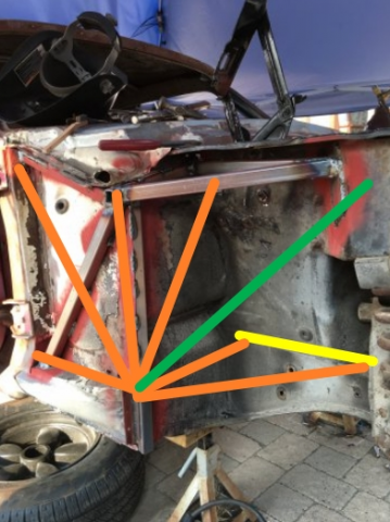
On my race car there's no cowl so I only have the firewall with no support. My cage will look overly complicated and heavy but only the required safety tubes need to be full thickness. The rest are of the same diameter but much thinner. The green line goes from the lower rail to the upper rail to the top strut mount. The yellow rail is tubing the sits on top of the normal engine frame rail, this is somewhat weird but based around some stupid SCCA rules that I'm working around. The tubes that connect the corner to the yellow tubes are what usually go to the TC pickup point. The idea behind all this is not only to make the car stiffer in torsion and bending but help protect the foot box in case I hit something hard enough to drive the wheel into this area.
On 11/10/2020 at 11:14 PM, 280Z-LS3 said:Here are some pics of front end bracing I did on my 68 Mustang.
The top tube against the firewall which forms the base of the strut tower triangle runs across the top of firewall just under sheetmetal lip providing support for the strut tower to firewall "export brace".
So it looks like you're well versed in all this. Nice work, BTW.
Hope this helps,
Cary
-
On 11/7/2020 at 7:14 PM, 280Z-LS3 said:
Cringing at the description of that crash. Does not take much to get into trouble. Physics is a bitch...
I am stealing many elements of bjhines' cage and chassis stiffening. Tying the TC buckets to rockers, upper frame horns to rockers and strut tower to above sway bar frame rail area with 1.5"x0.065" DOM. I think this size tubing will give enough strength while minimizing additional weight.
I don't think you need to go that large. I'd use the same tube as you would for a strut bar for the purely torsion stressed members unless you already have the material. It will just weigh a little more in the end.
On 11/7/2020 at 7:14 PM, 280Z-LS3 said:
I think you are suggesting adding a tube from rocker (connected to the TC tube) to frame rail along the floor pan where it starts to angle up which is easy to do. Adding structure from rocker to trans tunnel under seats is easy too but how to carry that strength across the trans tunnel? Any ideas other than trans mount? Having the driveline and exhaust mocked up will certainly help determine what is possible.
I think you have a couple options. You can do it in tube similar to what you have or was used on BJHines car. The other is to make a larger torsion box out of sheet in similar thickness as the rest of the car. Look at the convertible torque box mod for Ford mid-to-late 60s Mustangs and Falcons. They have a very similar unibody design to the Z. In those they build a box that goes straight down from the firewall and then back into the floor. This connects to the engine bay side. Here's a couple of links to give you the general idea https://ironhydroxide.blogspot.com/2017/04/boxes-of-torque.html and https://ironhydroxide.blogspot.com/2017/05/boxes-of-torque-part-dos.html. I've also seen this extended down to the level of the outer rocker lip and boxed into the inner rail.
Many of the IMSA Zs boxed in the outer section from the upper rail to A pillar down to the rocker. This makes that more of a torque box out of that section and can tie in nicely with something similar to the convertible Mustang mods. Getting across the tranny tunnel is going to require a brace under the bellhousing area or you add internal rails that go from the front frame rail up and over the tranny tunnel and down to the next side. If you look at newer cars you'll see they have integrated a 8 to 12 point cage into the unibody design. They just do it with folded metal rather than DOM tube.
For a street car that may do some track work I think meshing the torque boxes with the tubes in the image above would be a good way to go. The new Mazda RX8 is a very stiff unibody compared to all their previous cars. If you look at images of it and compare to older models all these little details start to pop out. However you go I really like what you've done. I need to get some projects out of the way so I can get back to cars myself and put this year behind me.
Hope that helps,
Cary
-
On 11/1/2020 at 7:21 PM, 280Z-LS3 said:
I welded in the Bad Dog frame rails last because was contemplating incorporating some captive nuts inside the rails for the trans mount. After giving that idea more thought the complexity of pulling that off just killed my motivation. Instead going to build the trans mount off of some extra support structure for the floor pan. The bottom of the S30 chassis is a weak point and would like to address this while cutting up the trans tunnel to fit the Cobra Suzuka seat (my 1975 has the intruding bulge into the driver's seat area). Heavy85, a member here, crashed his Z into a small boulder field during a hill climb event. He posted an in car video and after math photos. His crash hammered home the need to build some strength and crash protection below the passenger seats. Getting ahead of myself a bit as this has yet to be design...
I love the level of work you're doing. The crash comment is one I've thought a lot about too. About 20+ years ago (vague) I witnessed the aftermath of a Ford Falcon leaving the road at not much speed and hit a tree. This was well below normal racing speeds (hillclimb event) as the road was wet. The driver suffered a broken leg, pelvis, and now walks with a limp. Why I bring this up is that the underside of a Ford Falcon is very similar to the Z cars. His car had a good cage and a racing seat. How he got hurt was the car rolled off the door bars when he went sideways into the tree and floor deformed as it was the weak element. And while he was held in his seat the car deformed and like a large lever broke his leg at the edge of the seat. To this day I can vividly recall his screams as the emergency crew removed him from the car.
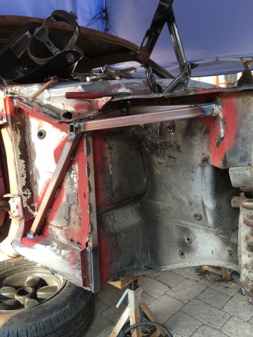
Making the floor stiffer is a good thing in my book. There are still a couple of areas to think about depending on how you intend to use your car (some could be handled by a cage). The main one I've seen where there's a problem is the engine compartment to passenger area. While you have the Bad Dog rail help there's no lateral protection in the front. I've heard that a few big crashes in Z cars have resulted in broken ankles as this area can fold in on your feet in a wreck. If you look at new cars they have structure that goes from the inner rail to the outer and this can be triangulated to the TC and upper strut mounts. Here's a picture of what I'm talking about. I have more ideas on fixing the firewall too based on newer cars.
On 11/1/2020 at 7:21 PM, 280Z-LS3 said:Here are some pics of progress to date.
Some weld thru primer before install of frame rails
-
17 hours ago, 260DET said:
If I was doing a LS swap again a dual clutch transmission would be on the list for sure. Kits are becoming available for the LS too, faster easier shifting and less stress on the drive train.
I'm planning on using the BMW DCT in a street car build. I weighed the costs of it against a T56 and the heavy duty 5 speeds transmissions and it was comparable. With the right ECU you can automate downshifts with throttle blip and all. Amazing what parts are becoming available for our cars.
Really cool to see a Z banging around Bathurst with GT3 and V8 Supercars in the mix. Go team Z!
Cary
-
What are you planning for heater/defrost vents and will you use the Z heating assembly or the miata unit? Very curious for my street car project.
Cary
-
1 hour ago, Ironhead said:
I don't know honestly what is "correct practice" (you will get a bunch of opinions) but I did stitch weld this area, for whatever that's worth (not much).
The one advantage is that you know the parts are now solid and not relying on 40 to 50 year old spot welds. And if you do ever bend it you can pull it straight. With just the spot welds they often shear and you can't pull the complete part. I learned this from talking to a number of unibody racers and seeing first hand when they did pit repairs.
Cary
-
On 9/21/2020 at 6:47 PM, Zetsaz said:
Depending on where they're placed I might be interested in some select pieces. My car already has sound deadening and some other things, so I'm pretty limited in how much more I can do for chassis reinforcement if it involves welding under areas that have material applied,
One thing I've played with is using some of the late model car epoxy bonding. If the parts have good fit this seems to work, ideally probably needs some rivets too, which might be another problem that interferes with the sound deadening.
Cary
-
As others have stated it's probably too low but it also somewhat depends. What are the diameter of your tires? And if your suspension arms point up towards the wheels then you are too low and will be in the nether regions of the suspension geometry.
-
There's a better way to do this but what you have will work too. If you mount the rod ends on the crossmember and then have the brackets on the control arm. This way you can change alignment but not cause changes to your camber curve or roll center. The third option is to let the inner end of the trailing arm float (no connection) and use a lateral locator behind the diff.
I'll see if I can dig up some old pics and attach to this thready.
Cary
-
On 7/31/2020 at 12:08 AM, 260DET said:
Interesting comments and I think that you have nailed the crucial weaknesses in the stock S30 body for race use. Basically the fire wall does not sufficiently connect forward to the front suspension load points. Also the attachment of the front X member which bolts to the rails, the stock four bolt setup allows flex, it's simple to add a couple of brackets forward to bolt to the rails.
Do keep in mind that the way the crossmember is bolted in is considered a safety feature. It's designed to shear in case of a heavy frontal impact and allow the engine to go under the car rather than through the firewall. The downside to all this as you mention is there isn't a lot of stiffness available for the strut tower or the front suspension points. When you look at newer cars it's interesting to see just how much additional structure they have put in place in these locations.
Cary
-
On 6/16/2020 at 5:59 AM, jjslade said:
Hi there, I have a 260z with the following cam, 284 advertised duration....210 at .050 duration with .435 lift on 109 degree LSA, would you guys reccomend the 40 or 45 triple webbers? and also would the stock mechanical fuel pump be adequate?
It depends on what size chokes you plan to run. 45s with small chokes (aux venturis) flow less than 40s with similar size chokes. If I recall from memory that 33 mms is about the cutoff point where you'll find this difference. This will be an expensive and you want to think about what are future plans for your car.
The other option would be EFI throttle bodies rather than carbs. This will be more expensive but probably offer better driveability.
-
Thanks for pointing this out. I removed the spam. I'll let Dan know there seems to be a reporting error.
-
As jobill stated you need deeper retainers. Nissan Comp used to sell ranges that had to be used for specific depth lash pads. A quick google search turned up many companies that seem to have the parts. You also need to make sure these don't alter the installed height of your springs or you may end up in coil bind or not have the correct seat pressure and then have valve float issues. Sorry to say that the wrong parts were used when you're engine was built. At least you didn't have the rocker fall off and get in their sideways and royally screw up the cam, which happened to me when I learned you couldn't mix and match parts.
Hope that helps,
Cary
-
The really nice thing about switching to aftermarket calipers is you can get almost any pad in any compound. I've had good luck with Performance Friction. They no longer sell the same material I used but it was a medium torque, good initial bite, great release, and long wearing while easy on the rotors. This was the 01 compound. They now have a new compound that is supposed to be even better, the 11 is what I'd try. Keep in mind when they say medium torque they are looking at braking in the 1.5g to low 2g range. Stay away from the high bite stuff unless you're packing a lot of downforce. Or it will be skid city.
-
I use a higher temp race pad on mine. You need to do some preheating to grid or warm things up some other way. It can make the first run rather dicey if you can't get heat into the brakes and pads. But having consistent braking with the rotors glowing red is really nice. Now only if the car was back together sometime this decade.
-
I think the biggest reason for replacing the harness is its age. All those wires and connections are getting very old and who knows what you have for corrosion and any work hardening of the wire. It's a huge PIA to rewire a street car but you can use the existing harness as a guide and remove/add what you do or don't need and go from there. On modern cars you have a much higher amperage in the charging circuits so all that wiring, fusible links, fuse block need to go. And you're already pitching the engine harness for your Holley ECU so there's little left in the front. You'll most likely replace all the gauges so much of the dash wiring will be changed. And you can see it's not that much of a stretch to just replace it all.
In the end you'll probably have a more reliable car and in the event something is wrong you'll know where all the skeletons are buried. If it's any consolation that's my plan on my street car project that I hope to start working on in the next year. Painless seem very proud of their products and I think you can find competitors that are less expensive and feature similar materials and workmanship.
Hope this helps,
Cary
-
Guys let's try and keep this on topic, which was thoughts about the subframe. If you want to discuss business practices that should probably a different thread. I'm not saying you can't do this but this is the drivetrain subtopic. For what it's worth this is nothing new. I have seen/had this problem with all vendors not just Datsun specific parts. Any catalog that has the statement bolts-in is usually code words for if you can fab and have the tools to make it fit.
Thanks,
Cary
-
Did you weigh before the conversion?
-
2 hours ago, Neverdone said:
Personally I think you'd be better off triangulating the front side to reduce the moment arm your steering rack is going to be putting on it.
You definitely need to do this or you may have issues by bending on your rack and it might feel weirdly stickly. If you corner hard you put a lot of load in via the lower control arm.
Cary
-
One thing to add is if you push the wheel forward to gain more caster then that small difference will be closer to nil. Like Jon said if you try and remove via spot welds you better have a number of cutters available. I cheated and bought and air powered spot weld remover. It wasn't cheap but oh boy does it make this easier.
Cary
-
I can't speak directly about the 280ZX suspension in a Z but we once used that setup in a 510 for rear disks and CVs. It wasn't a bolt in by any stretch of the imagination. I did a lot of research into trailing arms and it seemed like one of the big problems is the toe and camber curves are reversed. If the arms are close to flat in side view when the car is running then a lot of this doesn't matter. Bit if you lower the car and the arms run at any angle pointing up or down then you get a lot of toe and camber change. Any alignment change (toe or camber) will move the suspension pickup points and that changes a lot of other things. Add a lot of power and the car squats getting you into these outer extremes.
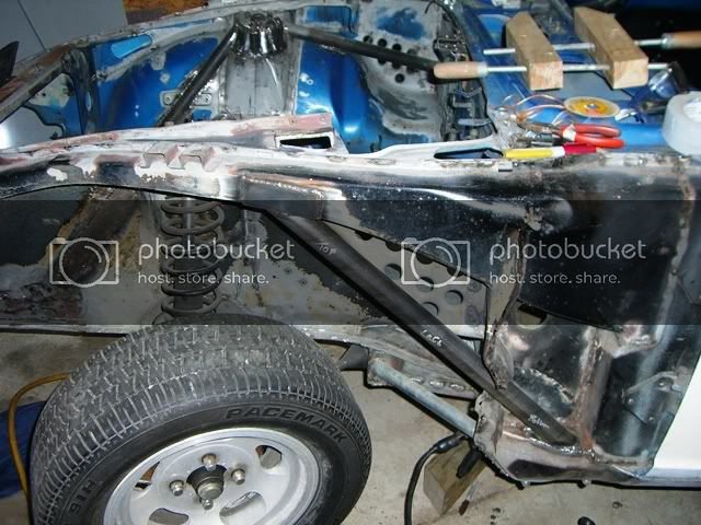
To get around this we made a custom crossmember that had about half the trailing arm angle (similar to what BMW uses) and fixed the pickup points on the crossmember. All adjustment for camber and toe was on the arms. This along with mounting the crossmember higher in the car allowed it to operate in the sweet spot and worked really well on this 510. Previous attempts with the stock suspension included ever stiffer rear springs, which helped as long as the surface wasn't too bumpy. On my own 510 I tried a Z bar for a while and that really helped with squat and lift. Here's a Sierra example and you can see the fab work to reduce the trailing arm angle.
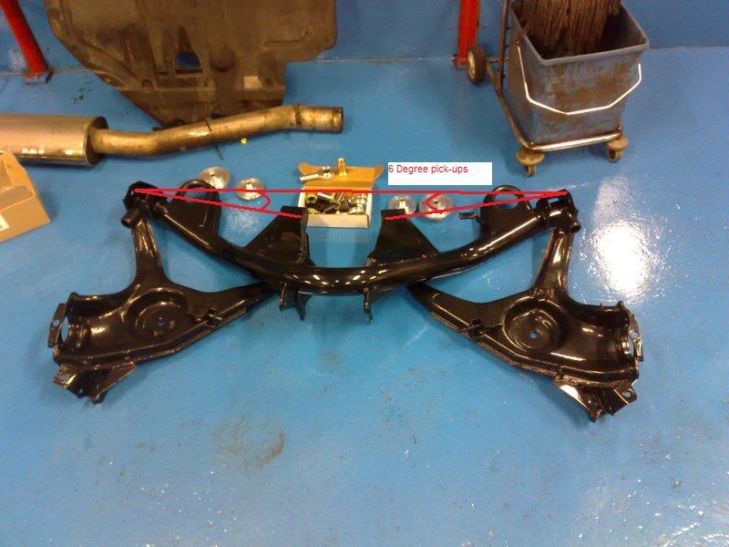
If I were to do it again I would have used the rules that allowed any axle locating device to create an extra arm that would run behind the diff and connect to the trailing arm to control lateral load. Then use the outside mount on the cross member and not hook up the inner mount. You end up with the equivalent of what Subaru uses on many of their cars. Here's an example below, which is from a thread where Richard is talking about what he's going to do on his Z31.
-
 1
1
-

Using 5/8 bolt in place of spindle pin
in Brakes, Wheels, Suspension and Chassis
Posted
The one thing that hasn't yet been mentioned I'd like to point out is get a bolt long enough so only the shank is against the bushes. If you buy a bolt that fits it will most likely have threads in one of the bush ends. I don't think I'd recommend notching for the spindle pin as this will add a failure point and this system doesn't have the fail safe the stock system has. If you do decide to notch the bolt make sure to paint of put some corrosion inhibitor on it.
cary