rand
-
Posts
23 -
Joined
-
Last visited
Recent Profile Visitors
2649 profile views


rand's Achievements
")
Newbie (1/14)
0
Reputation
-
240Z Trouble bleeding rear brakes
rand replied to rand's topic in Brakes, Wheels, Suspension and Chassis
Great news! I rebuild the wheel cylinders and (partially) rebuilt the master this weekend, and things seem to be working. Unfortunately the master cylinder rebuild kit I got was only for the 70-72 Nabco and I have a Tokico. The only parts that seem to fit from the kit were the rubber rings that hold in the check valves. It seems like the issue was the wheel cylinders all along, but I ordered myself another master rebuild kit from classicgarage.com, so I'll see if that one works out at some point. My last question is do I need to do anything special to adjust the rear brakes once I have the drums on? I cranked the adjustment wheel out until I could barely get the drum on, but is there any further adjustment necessary? I read that they're "self-adjusting" but does that apply only to the handbrake? Here's some quick triumphant videos: Rear cylinder actuating Basic brake functionality confirmed -
240Z Trouble bleeding rear brakes
rand replied to rand's topic in Brakes, Wheels, Suspension and Chassis
Got it - I just ordered myself two wheel cylinder and one master cylinder rebuild kits. Hopefully I can rebuild them all this weekend with new seals, and I'll report back. Does anyone have a preferred how-to video for rebuilding? -
240Z Trouble bleeding rear brakes
rand replied to rand's topic in Brakes, Wheels, Suspension and Chassis
The pedal moves a significant amount when I press on it, even with the bleeders closed. I haven't observed any fluid leaking out since I reassembled everything. I totally disassembled the cylinders, and other than being filled with gummy fluid they were in good shape. I cleaned out the cylinders and was able to easily push the pistons in and out freely. -
I'm trying my hand at bleeding brakes for the first time on my '71 240Z that I got from my father-in-law and am having some trouble. After pulling a bunch of components* off and cleaning them out, I can finally get a good stream of fluid out of the bleeders with no bubbles using the old glass jar method. The problem is that when I close off the bleeders and press on the brake pedal the wheel cylinders don't budge at all. I would expect to be able to see them actuate at least a little bit even with no vacuum on the booster (the engine isn't installed yet). Is that a reasonable expectation? Anything else I can do to debug this? I'm really hoping the wheel cylinders aren't shot, as they're the early models and are crazy expensive these days. Is there any easy way to tell if these are the problem? * These are the components I've pulled off so far. I've blown compressed air through everything to make sure there are no blockages. "Pressure Regulating Valve" (#1 in the Haynes manual) - the seal had some gunk in it, but otherwise was in good shape The Y splitter next to the pressure regulating valve - pretty clean The soft lines going to the drums - one of these had a huge wad of gummed up fluid stuck in it that shot out like a rocket The hard lines connecting the soft lines to the cylinders - totally clean The wheel cylinders - these were filled with gummy brake fluid, but once I cleaned that out they seemed to be in good shape as far as I could tell. One of them was missing a spring, so I'll need to find a replacement. Thanks!
-
So it looks like the throwout/collar/fork from the 4-speed definitely won't work on the 5-speed. I'm going to buy a collar/fork for the 280 and see how they fit. I took a video to show what the 4-speed parts look like on the 5-speed here:
-
I'm in the process of rebuilding the L24 out of my 71 Series-1 240Z. I was planning on using the original Type-A 4-speed transmission, but recently found a close-ratio 5-speed and decided to get it. I stupidly bought a clutch for the 4-speed a year ago (this one), so now I'm wondering what parts I can still use and what I need to buy. Would someone out there mind taking a look at my parts list and give it a sanity check? Slave Cylinder: I'm assuming the old one isn't going to fit the new 5-speed, so I'm planning on buying this one Clutch Collar: Can I use the one out of the 4-speed, or should I buy a new one? Clutch Fork: The transmission didn't come with a clutch fork. The one from the 4-speed seems to fit, but I figure I should get the one that's meant to work with the collar and slave cylinder (this one). Clutch: I already bought this 240Z clutch, so it would be nice if I can still use it. I have the original flywheel that I'm planning on installing.
-
@ZHoob2004 Thanks, I think you're right. The Monroe book hasn't told me to find an accurate TDC with a degree wheel yet. I've only zero'd it out with a dial indicator before the head went on. I'm ordering a degree wheel and piston stop online now - I'll get it to TDC and report back.
-
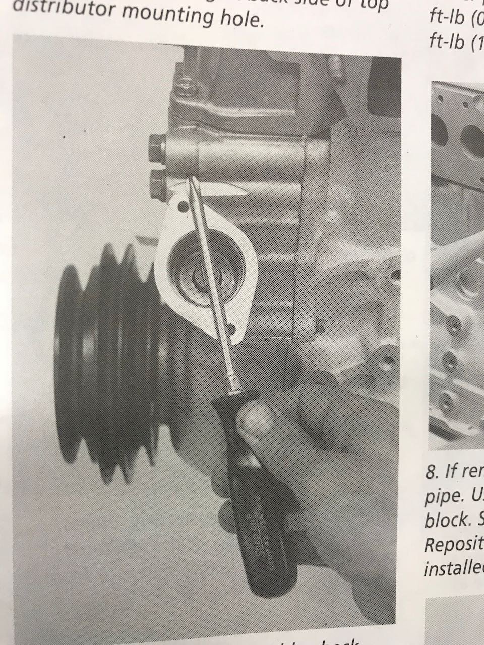
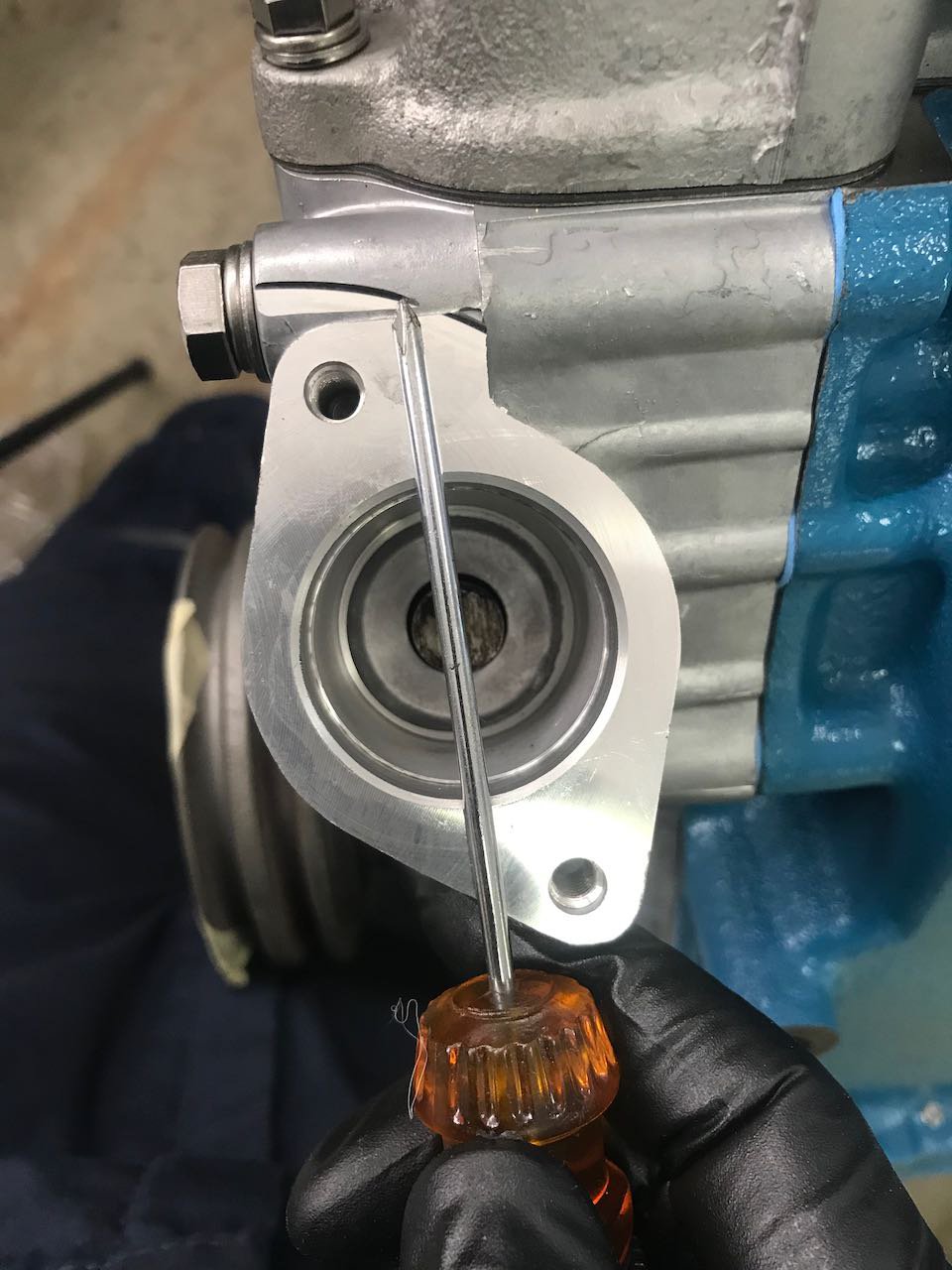
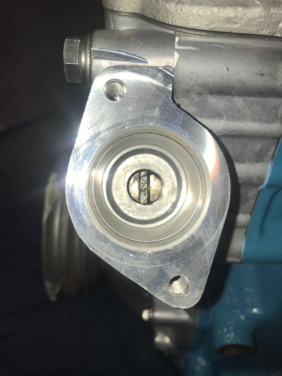
I'm following the instructions in Tom Monroe's "How to Rebuild Your Nissan & Datsun OHC Engine" and I'm at the step where I need to install the oil pump and distributor drive shaft. In the book, he has a picture of the angle of the installed shaft relative to the distributor mounting face. I've tried pulling and reinserting the shaft for about 30 minutes (slightly rotating it this way and that each time) and can't figure out a way to get the angle any closer to what's pictured. I can either get it installed way more clockwise, or way more counterclockwise. How important is this exact angle? Tom's instructions: My best effort so far:

-
For anyone who ends up with the same problem, here's an update: I just talked to my machinist and he said that this is a common issue. Apparently bearing manufacturers sometimes oversize the thrust surfaces with the expectation that you will be resurfacing and removing material from your crank during the rebuild. This is usually indicated in the catalog, but apparently was not for my bearings. You can get them down to size by laying a piece of ~400 grit sandpaper on a piece of glass, spraying some WD-40 on and sanding down the front surface until you get the clearance you need.
-
I just read ahead in my Tom Monroe book, and he says: Looks like I'm just one of the rare unlucky ones. Has anyone out there successfully sanded down the thrust surfaces on their bearings? Any advice?
-
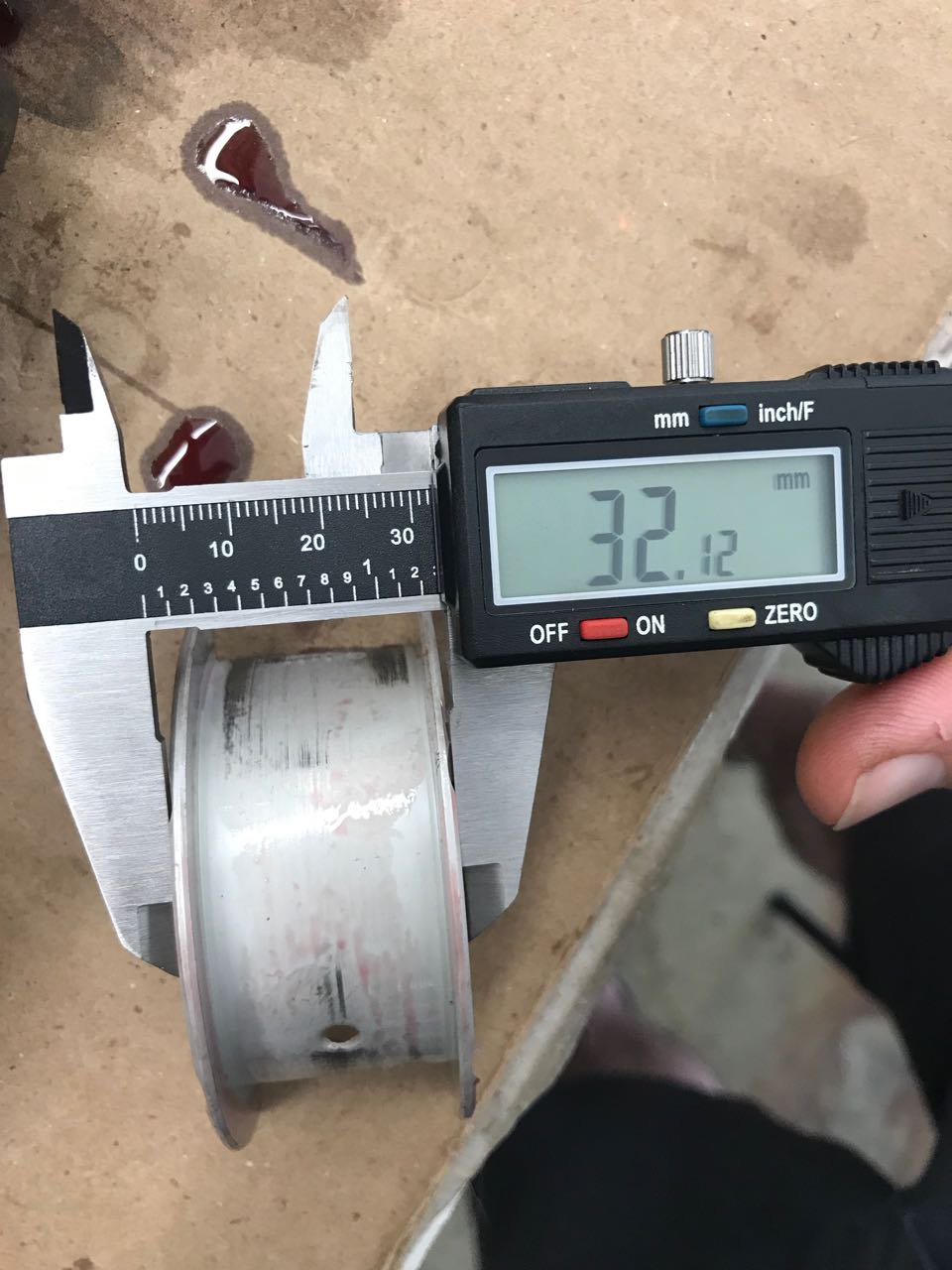
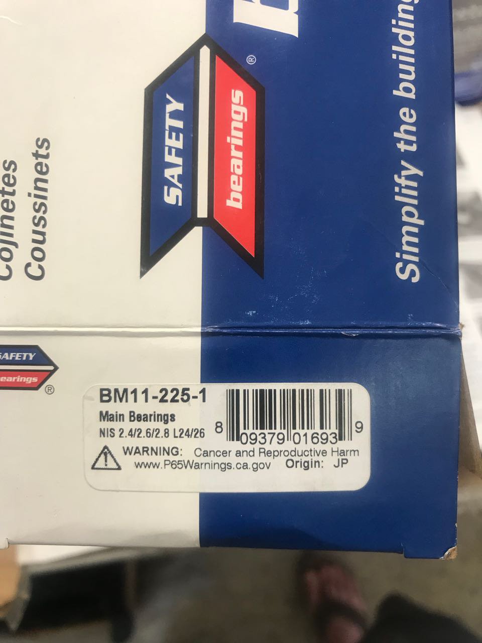
I'm re-assembling the L24 out of my Series 1 240Z and just tried dropping the crankshaft in. It dropped in with a tiny bit more encouragement than I expected, but that center bearing was so tight that I couldn't turn the crank once it was in. I pulled the crank back out to investigate, and that bearing came with it! It was on so tight that I had to lightly hammer it off with the butt of my mallet to get it back off. I assumed that the bearing would have just slipped onto the journal rather than needing to be forced like that. My crankshaft was ground down by 0.25mm, but I can't imagine why that would make the thrust surfaces tighter. I measured the center bearing width and it came out to 32.12mm, but I have no idea if that's nominal or not. I couldn't get a good read on the crank width at the center journal with my calipers. This is my first time building an engine, so any advice is appreciated. Is this kind of interference fit expected here, or should I send my crank back to the machine shop, or just order new bearings? Thanks! See pictures below. The box that my bearings came in. These were provided by my machine shop. Caliper reading on the width of bearing. Notice that the back of the bearing is now scuffed up. When I tried turning the crank one way, the bearing tab prevented it from rotating. When I tried to turn it the other way, the bearing just rotated with the crank and scuffed a little material off its back as it went.
-
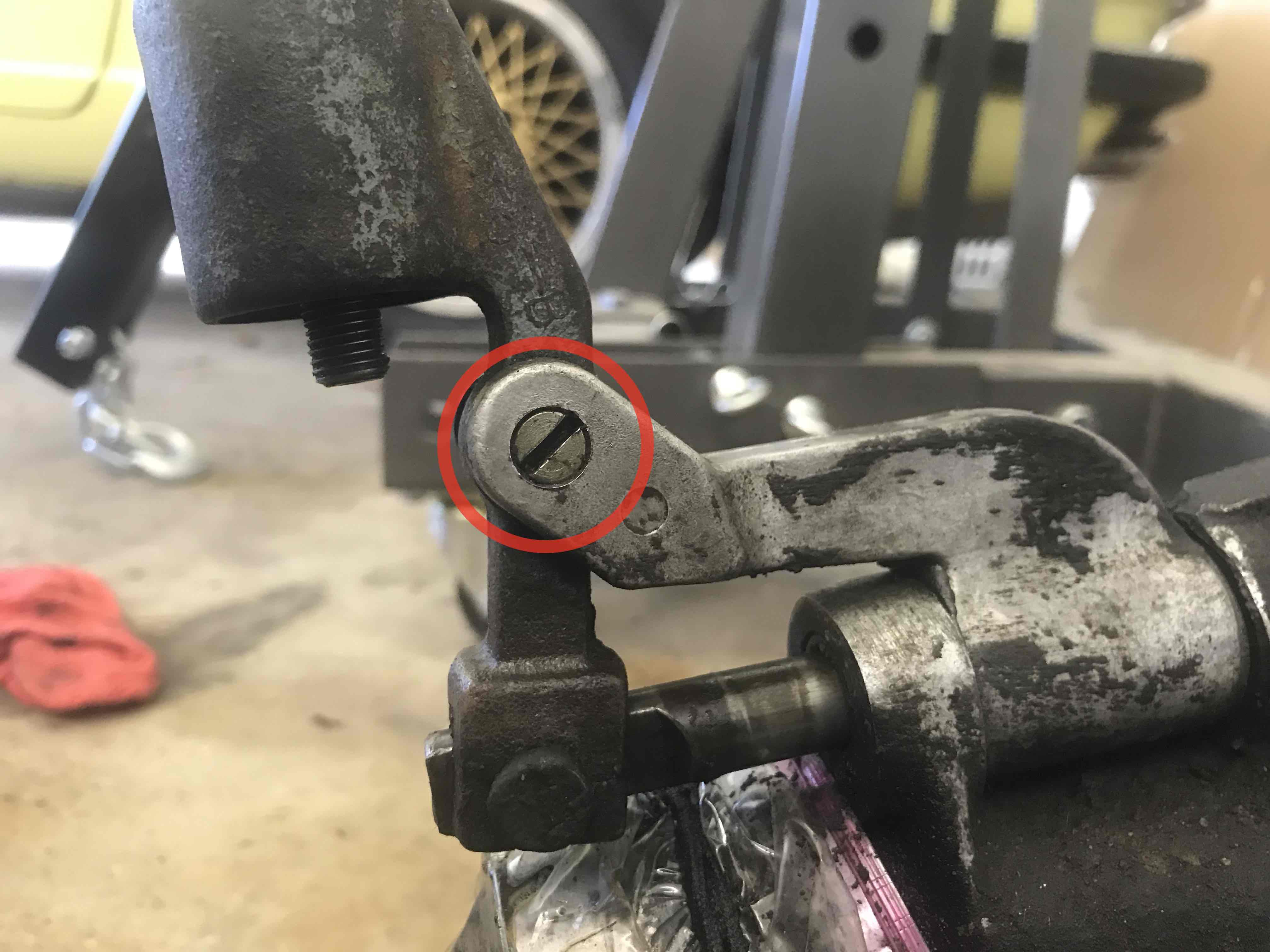
I have a F4W71A transmission from my 71 240Z that is sitting on the floor of my garage while I rebuild the engine. The shifter has that loose "monkey motion" which I'd like to try to tighten up while it's out of the car. I'm thinking that if I can take off the shift lever, I can probably just squeeze it in a vice to take up the play between the prongs. If that doesn't work, I could try heating it and banging it on an anvil. Has anyone out there done this successfully? Removing the C-clip and pin from the bottom of the lever is easy, but how do I get the pin out of the upper pivot (see pic below)? It looks like a flathead screw, but trying to turn it with a screwdriver got me nowhere. Video of loose shifter:
-
Does anyone have any shops they recommend in the Los Angeles area? I'm looking to have someone rebuild the transmission from my 240.
-
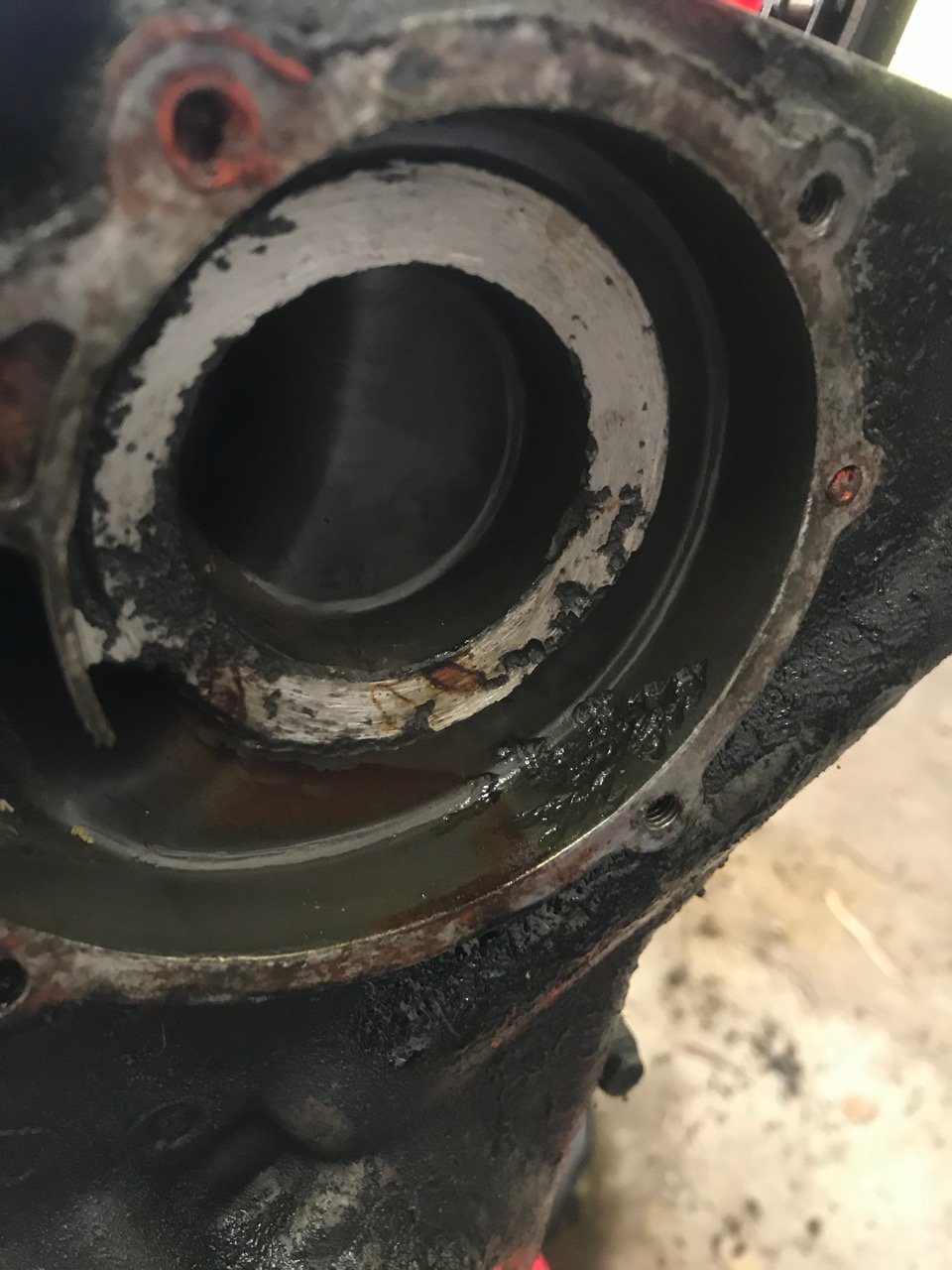
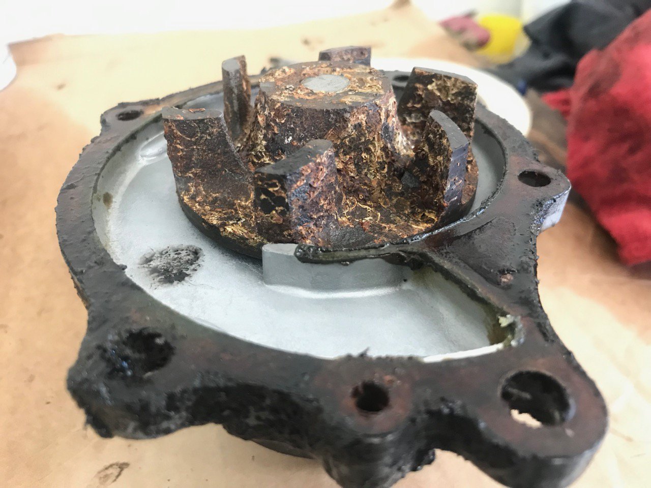
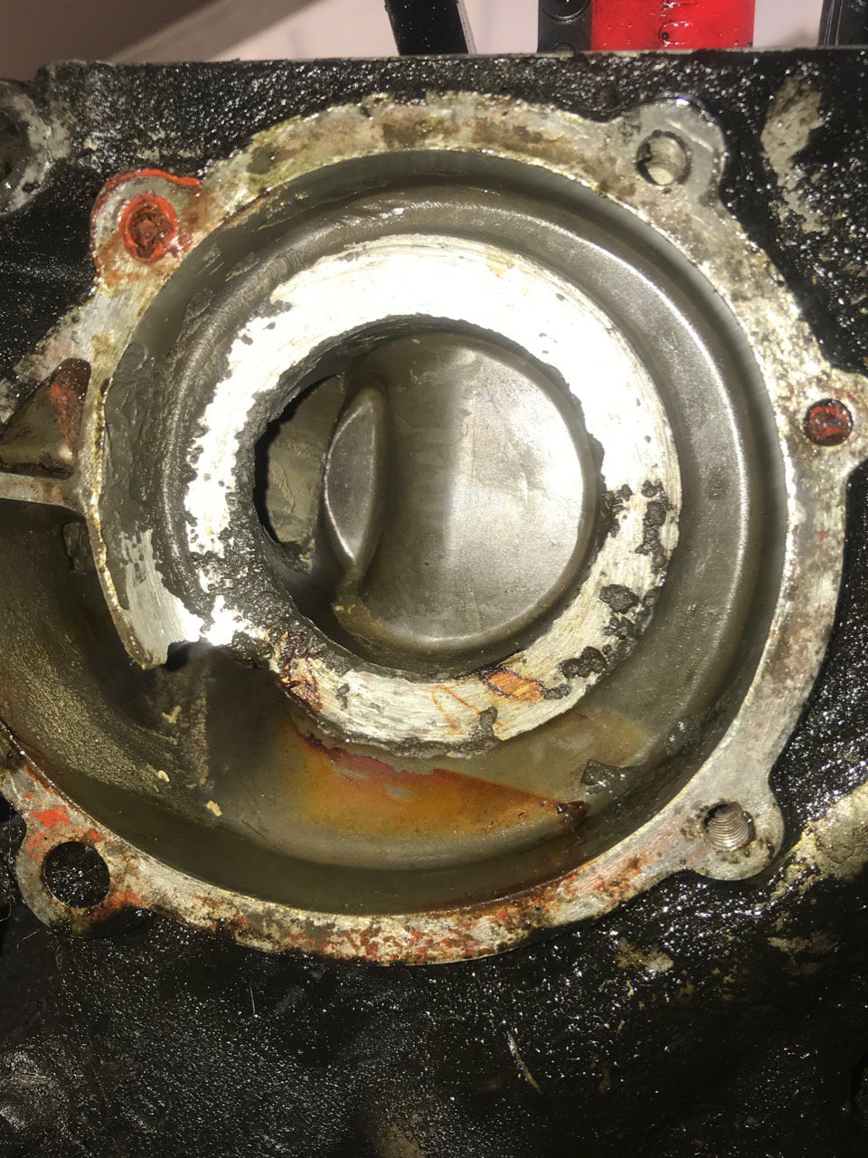
I've pulled pretty much everything off of the block now and am getting ready to bring it to a machine shop to get checked out and cleaned up. I was looking at my timing cover, and the area underneath the water pump is pretty badly pitted and scarred looking. Am I going to need a new timing cover, or is it fine to just run the engine with this one? I don't mind replacing the water pump, but timing covers are pretty hard to find. I saw a few on eBay, but they were around $250 😐
-
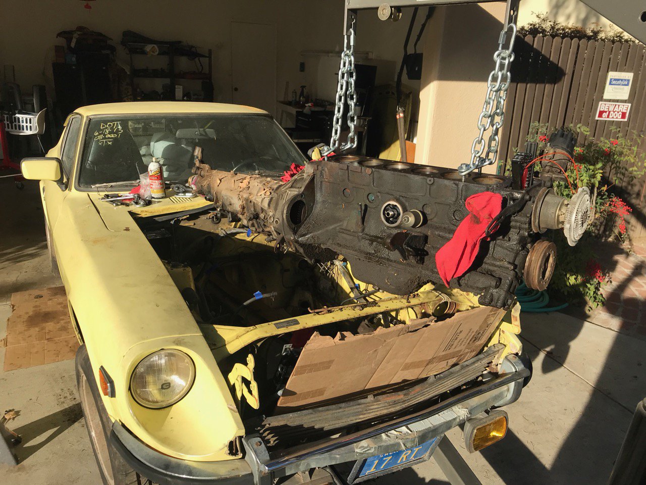
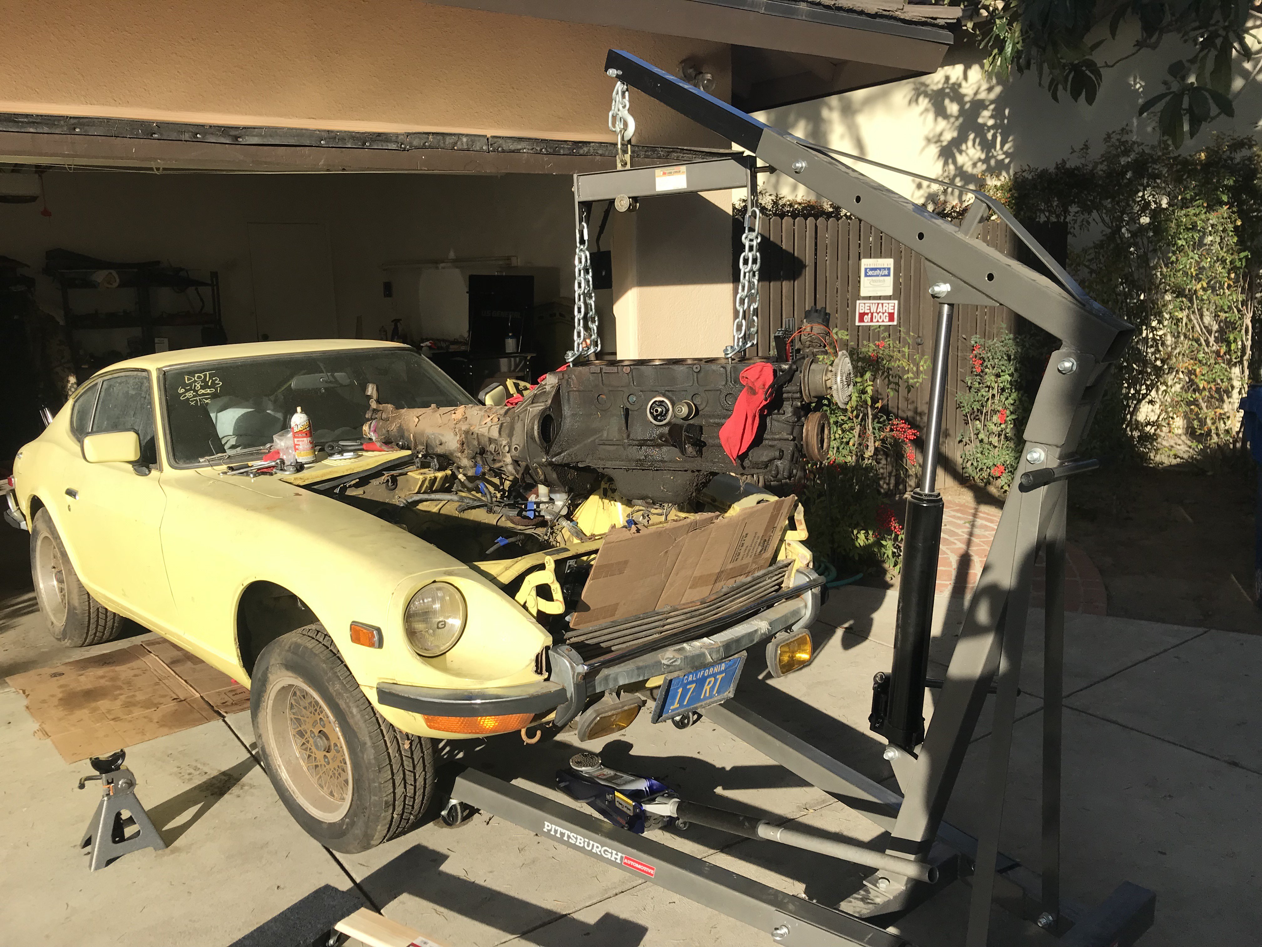
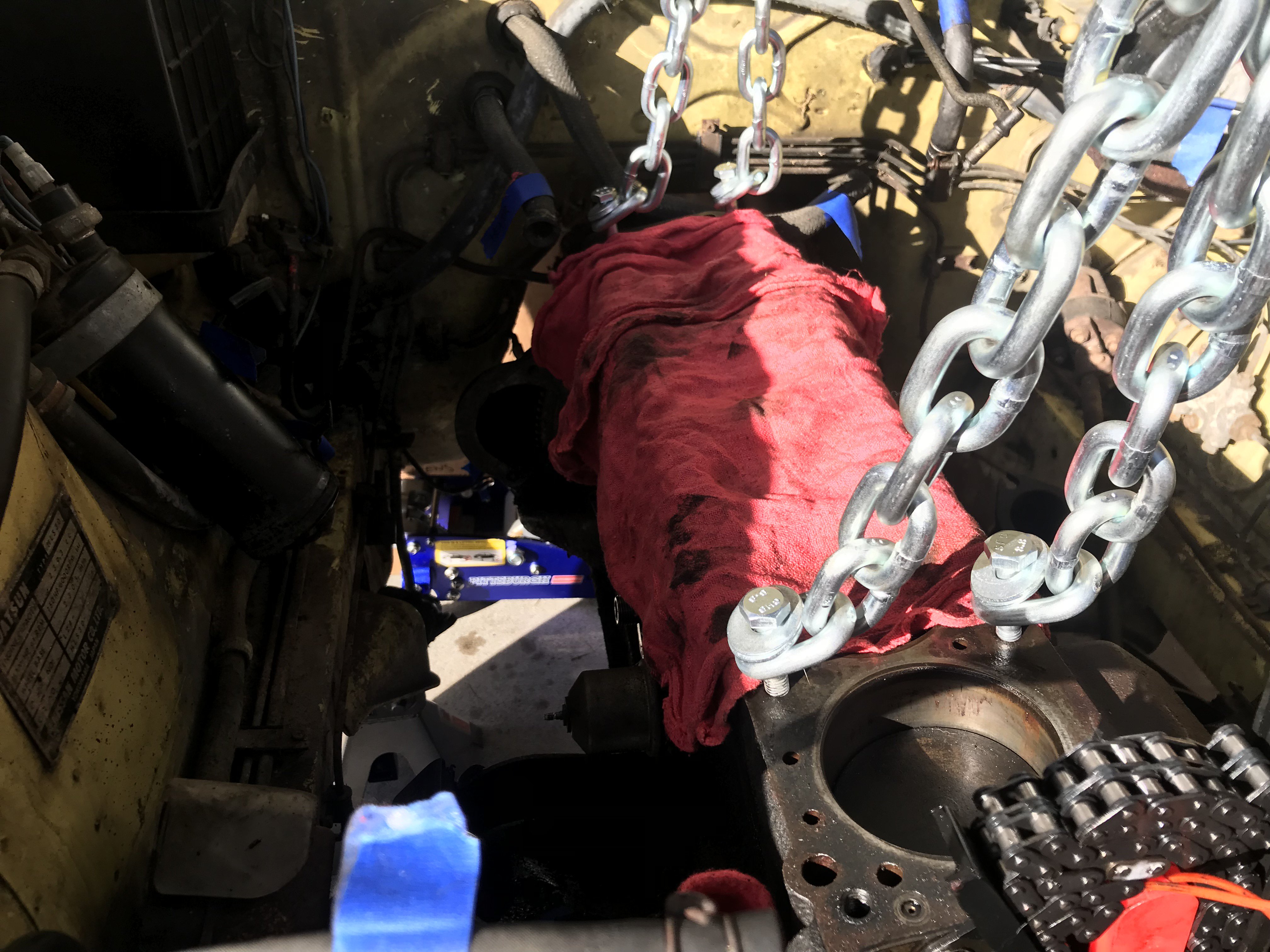
Just wanted to follow up on my results on pulling the engine with the head off. I ended screwing some bolts in into the head-bolt holes with some chain and washers on them. It worked great and was pretty easy to do. Pictures attached.


.jpg.ddc2c94b6622970d94ab52f0c9c45bdf.jpg)