

clarkspeed
-
Posts
877 -
Joined
-
Last visited
-
Days Won
47
Content Type
Profiles
Forums
Blogs
Events
Gallery
Downloads
Store
Posts posted by clarkspeed
-
-
Nope. But I could probably come up with something if financially motivated. Of course it would not pass at a concours show. Not even close. It would need to be printed in multiple parts.
I am currently working on a fairly large airbox using a big rectangular Audi filter element and a 4" hose inlet. Could easy adopt it to a SU's if I ever finish it.
-
I think I posted this on Hybrid before. Here is a good video on how F1 cars use vortices to seal the sides and do lots of other things.
-
6 hours ago, calZ said:
6. I don't know if I agree with calling airdams a crutch, but an airdam without a flat floor is leaving a lot on the table. The less air you let under the car, the easier it is to manage and the easier it will be to make your diffuser effective. That's true with or without a flat floor. If you put a flat floor on but leave your front end the same, you're still going to generate a bunch of lift on the bottom of your front bumper for anything shaped like a Z. Modern cars are pretty good at not having much upward-facing area, but old cars with the diving board bumpers really need airdams.
Thanks for your comments! Cool job.
I know virtually nothing about vehicle aero but i am a mech engineer so I can grasp the concepts. Even with my meager knowledge, Edgar's book seems to have some funky conclusions.
I just reread the flat floor section again last night. What he recommends is a slightly rounded panel roughly starting at bottom of the front bumper to a smooth rounded transition knee point in front of front axle. Then totally flat section back to where the diffuser starts. And the diffuser being the minimum of another flat panel angled upward at 10 degrees or more to the rear bumper. The start of the diffuser section seems to like being as far forward as possible. With this arrangement, you want as much air as possible flowing under the car and no airdam. So no extra drag and net downforce like a reverse wing. I am still struggling with this. It seems like what interference you do have with suspension arms and maybe wide wheels would screw this up. Also it seems ride height would be a critical factor. For an S30Z I assume this would look like a short full width airdam, with the curved floor section attached at the bottom lip.
-
Well I am about 40% through this book now and it does not necessarily match what I have read in magazines, Internet, or anywhere for that matter. Many of these concepts are not intuitive. I will try to list out some of the salient points I am tracking. I don’t think Mr. Edgar would mind since I am only scratching the surface and promoting his book. In my own words.....
- Cd, coefficient of drag, is not an exact measurement. Almost impossible to measure without only the best wind tunnels. Most manufacturers quote a number from less accurate wind tunnels and no one can prove or disprove what they post in their marketing material. Coast down testing is a disaster at best, not repeatable. Way too many variables come into effect at speeds below 60mph and a perfect consistent environment is impossible to achieve. Edgar proposes just measuring the change in drag rather than trying to quantify it.
- Vehicle aero is complicated. More complicated than CFD analysis can fully cover. Even if you can simulate the flows over a car, the flows under the car and side winds (yaw) cause unplanned effects. Even the best OEM aero specialists have to experiment, measure, and rent wind tunnels. And for OEM’s, style often takes precedence over aero.
- Every standard vehicle shape creates lift. Air speeds up when it is required to change directions quickly so the transition from grill to hood and window to roof speeds up the air and creates low pressure. The amount of lift depends on the area of these surfaces. Some lift is created in the rear transition from roof to rear window. So most all cars without any major aero features create lift. The lift/downforce can be different at any point location front to rear on the top and bottom surfaces of a car. The overall lift is the sum of all the points. Really the only exceptions are supercars with splitters, flat bottoms, and diffusers. Not Camry’s.
- Since most all cars create more lift the faster you go, then obviously it is not such a bad thing as long as it is not excessive. Counterintuitive, more lift in the front than rear gives a feeling of stability. Yes, you read that right.
- Drag and lift are related but totally different. Decreasing lift usually comes at the expense of increasing drag and visa-versa. Race cars obviously want as little lift as possible or even downforce. The performance gains usually outweigh the increase in drag when done correctly but you have to be aware of both.
- I will not go into all the aero tricks available to reduce drag and increase lift. Edgar goes into pretty much any mod you can think of with pictures and suggestions to make more effective. However he emphasizes, modification to the underfloor, adding a flat bottom, is the best place to start and gives the most benefits. He has plenty of examples on how this should be done. Air dams are basically a crutch to prevent as much air as possible from going under the car and hitting all the "stuff" hanging down there. A flat bottom is more effective and can make negative lift. Most newer OEM designs exploit this.
- Even small splitters can make large downforce but it is in front of front axle, which creates lift in rear. Same problem for rear diffusers and spoilers. They create lift in front because they are behind rear axle. You have to be careful with these mods to get a balanced car.
-
Thanks Mike! Glad you are still lurking around!
-
 1
1
-
-
Thanks for the kind words.
Basically Redshift purchases a full coilover package from BC. I tried to pick and choose some components since I already have camber plates and springs, but was not successful. It comes as a kit. They then take the strut cartridge and revalve to your specifications, in most cases is based on unsprung weight, sprung weight, and motion ratios or your own recipe if you prefer. They dyno at multiple settings and ship the kit to you.
The struts are 32 click adjustable and the adjustment combines both rebound and compression. The nominal setting is at the bottom 1/3 of the click scale or around 10 clicks. A sample dyno is below (not mine). I also ask if they were racer rebuildable. He said they were theoretically, but the parts they use were not available to be purchased retail anywhere. As I said before, Chris was very patient and helpful. He offers a full rebuild service and his reputation seems very solid.
As far as spring rates, I plan to start with 250F/225R springs which I already have. I also have a pair of 275 and 300's. So I ordered the Redshift's with 6k/7k (336/392lb) to have another heavier set. Springs are cheap.

-
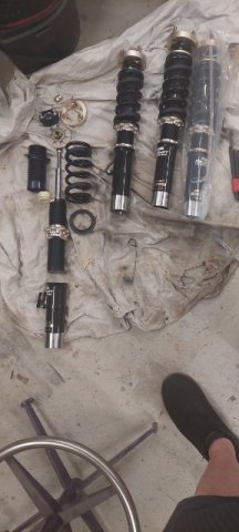
Well, I had some major setbacks the last couple months. A triple heart bypass put a little delay in the build progress. I thought I was a little young for this but such is life with family history. Feeling much better now 6 weeks later but still on the recovery. Not really ready for heavy lifting yet so trying to complete some of my easier projects. Anyway, here is a pic of the new Redshift dampers that arrived just before my hospital visit and a pic of the front struts I am prepping for the dampers. Sorry for the crusty bed sheet they are staged on. I am motivated to get stuff done, so hope to be back on the car in another week or 2.
The dampers are essentially custom valved BC coilovers to my specs. The single adjustment controls both compression and rebound combined. They came with full dyno graphs. I have to say the BC hardware looks to be of very high quality in the adjusters, hats, and camber plates. Chris at Redshift was incredibly patient and answered my 20 or so questions with detailed explanation and honesty. He seems to like emails to communicate but is very responsive. Can't wait to try these.
-
I jumped ahead and looked at the section on splitters. Seems he was a little late to the game. But when he tested a small one it ripped off his car. He then goes on to explain how it works and how to properly shape one. Seems a slight curved bottom is better than flat. And some profiles of leading edge are better than others.
-
On 10/30/2023 at 3:28 PM, JMortensen said:
I've watched a bunch of his videos on youtube and ended up buying a bunch of pressure pucks and five 1" manometers to do some track testing. Of course I bought all that shit and then put the car down and spent the next year doing other stuff. Still need to make a temporary dashboard to hold the gauges.
The one thing that he really bugged me with was his refrain that "you can't just slap a splitter, diffuser, and a wing on and make downforce" which he said quite a bit IIRC. I ended up linking in the youtube comments to AJ Hartmann's company, because that's exactly what he sells, and it obviously works. I haven't watched anything in a few months, but I did finally find one where he added I think it was a splitter and wing and was like: "HEY! That really worked!"
As you mentioned though, he has a ton of good info and practical techniques in his videos, I can imagine the book will be better. Did a lot of coast downs for drag measurement too as I recall. Anyway, thanks for the heads up. Will purchase.Thanks Jon,
This book seems to be everything he has done for 25 years all rolled up and adjusted to the latest technology of the last year or so. I'm about 1/2 way through but I can't find any aero mod you can do to a production car he doesn't cover in depth somewhere in the book.
Yes, he emphasizes no aero modifications should be made unless you measure the effect. It may not be what you expect and may upset the aero somewhere else. I am trying to wrap my head around how much lift a car, any car, produces. So for a production body style, you are basically trying to reduce lift, not create downforce. Exception being major mods like splitters combined with diffusers and wings. And as expected, lift and drag are 2 completely different things. Air dams reduce drag, splitters increase downforce forward of front axle only which can really lighten up the rear axle due to the lever arm.
One example on an air dam he tested a 4" deep and a 9" deep. The 4" reduced drag almost as much as the 9" and left greater ground clearance. He tests plenty of bolt on parts in the book and proves they work as intented. So obviously there are bolt on parts designed for specific cars that benefit lift or drag. But if you have to make choices or optimize the part, better be ready to test. Obviously a rear spoiler works on an early Z. But how tall and what angle is best to optimize?
-
1
-
-
Well I am going down quite a rabbit hole now. I recently ordered Julian Edgar's newly released book. Very down to earth and all practical solutions to testing and tuning production car aero on a tight budget without CFD or wind tunnels. For example he uses a throttle stop to measure changes that affect drag. Stop the throttle at 10 or 15% and measure top speed at roughly 50 or 60 mph. Make an aero change, then check top speed again.
Not cheap, but 500 pages packed full of info and lots of pictures. Highly recommended if you are looking to reduce drag and lift on your car.

-
1
-
-
Sorry, late to the party on a dusty old thread. The Toyota S12+8 solid rotor calipers accept a 2nd gen rx7 pad with just a light grinding on the metal backing plate tab that sticks out. I can't recommend the "best" pad for an application, but those rx7 pads come in any flavor you desire. You can search for the thread or I can provide more info if you need.
-
6 hours ago, AydinZ71 said:
@clarkspeed thanks Clark. Because the brake lines and masters were all newly installed, I struggled getting enough “throw” without having the front bleed with the rear. I bled the front first so they had little travel. The front would lock up quick and the balance bar would give me another 3/8” throw on the rear as it pivots. I bet it would be fine if my rear drum cylinder was not clogged, but I seemed to be just compressing air in the rear line.
going to get going on the rear drum-rotor conversion w/ the dynalite calipers. Thanks again for all the files you sent a few months ago! Il try to pick a reasonable rotor diameter so balancing with the fronts aren’t a challenge, and I’ll use your calc.
Yea, I could see that happening. A lot depends on the volume of the slaves. Luckily there is more than one way to skin the horse.
-
Bleed F and R simultaneously? Don't understand. Usually the balance bar self adjusts and allows you to bleed each wheel as normal. Feels wierd, but works fine. I don't do anything different with dual master as I would with a single.
Let me know what you are thinking. Usually a non issue getting rear too strong. I tend to experiment with rear pad materials if things are too outa-whack. I have run street pads in rear before.
-
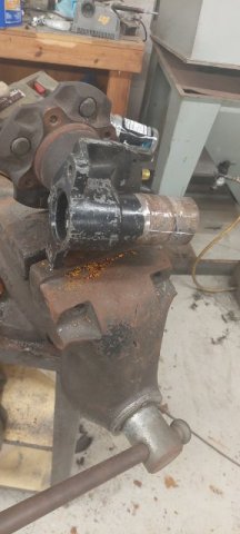
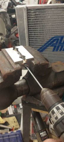
Couple pics. I had to fab my own pilot bearing. Bought something close from MacMaster Carr. Drilled it and honed the last .003" out to fit the tranny input shaft.
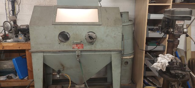
Also got a very large blast cabinet into the shop on a trade. Next job is to blast another set of strut housings for paint and then the exhaust system.
Many more pics coming.
-
On 9/7/2023 at 4:22 AM, jonbill said:
Surely your moustache bar is back to front?
What he said.
-
Cool.
With this type of build I would expect shimming the body somewhat just because the body may not be true. I hope your final assembly is visually acceptable.
Curious what you are shooting for for Ackerman. With the steering rack located in front of the front axle, you are limited on Ackerman %.
Good luck.
-
Sorry you are having to go through such a extensive quality inspection, but the time spent should pay back later. Some comments.
1. Record all your measurements and if you can add a feature to make it easier to repeat the measurement it will save time later. Like chassis center.
2. Are your bump steer measurements all in mm? A good goal is less than a mm over roughly 25mm of wheel travel. I think I would rather have the final rack in there to pass judgement.
3.might be easier if you jack the chassis and keep the wheel fixed to measure bump steer.
4. I didn't fully understand your chassis alignment issue but sounds like the control arm inner pivots are aligned and centered both front and rear? Just not square with frame? Not cool, but if the mounts are all aligned then kinematically the suspension should work as intended. Usually critical frame measurements are taken from the suspension mounts front to rear and X cross.
5. Looks like you have standard GM control arm bushings in there. Are they rubber? If so you might be getting some flex in some of your measurements.
6. Not sure of your ultimate goal, but if you plan on making a lot of alignment changes in the future you might consider recording all the coordinates and putting in a software program to simulate the impact of your changes instead of measuring after each change.
-
See above. R180 moustache and R200 are different and can be mounted backwards I think.
Always good to check if halfshafts are in alignment. You will also need to match angle of diff with angle of tranny equal and opposite.
-
On 9/2/2023 at 3:36 PM, AydinZ71 said:
Hey @clarkspeed.Bummer on the re-work and fit-up issues. I know how you feel! I’m experiencing similar difficulties, but I’m relying mostly on the OEM geometry. The sway bar is the only 100% custom aspect of my suspension.
I placed my regulator mount too close to my filter and have to do a loopty-loop of hose to make the connection. Annoying, but not worth the extra time just to make it “look” right. Hope you get everything worked out!
speaking of bump steer spacers: Greg said he had two 1” AL pieces welded together to get a 2” spacer. I guess Sam Neeve struggled to get his bump steer correct. I’m starting off with a 1” (since that’s the biggest off-the-shelf unit) and going from there. I found plenty of tutorials on setting roll center, but I have not found a decent one specifically for McPhersons yet. Let us know how you end up dialing that in on your car.
If you dig around on the forum you can find an excel roll center calculater I posted awhile back. It works for S30 z's. I still use it for a quick estimate. Yes, Greg uses 2 spacers welded together, and he runs a very low ride height. But I don't know what his front RC height is. I could probably guess. I'm sure it is above ground. And no trickery in the rear. His rear inner and outer control arm pivots are at or close to OEM location. Possible he runs higher RC in front than rear.
I have a 1.2" spacer I bought a couple years ago from TTT. I looked on their website and not see it for sale anymore.
-
On 8/31/2023 at 10:54 AM, jhm said:
Bummer, Clark…sorry to hear all that. You do one thing, and it affects ten other things. And the more custom you make it, the worse it gets! ☹️
At your convenience, would you mind elaborating a little on the control arm and steering geometry being “wrong”? (Causes, planned fixes, etc?)
Good luck with all the sorting!
On 9/1/2023 at 9:43 AM, jhm said:Nope....good explanation. How much caster are you shooting for, if you don't mind me asking? I'm guessing that remaking your steering rack adapters is a lot easier than making custom steering knuckles, as long as you can maintain clearance between the rack adapters and engine peripherals?
One thing I found when adding adjustable steering arms/knuckles and adjustable tie rod ends...using offset bump-steer spacers gave me extra clearance between the tie rod ends and the rims. Kind of like thick wheel spacers, without all the negative impacts of using thick wheel spacers. Without the offset, I would have had significant interference between the tie rod ends and my rims (15" diameter), like you described in your option #3 above. T3's new "evolved" design even has multiple mounting positions to tailor the amount of offset to one's specific needs.
I think I've got some spare 3/4" bumpsteer spacers (plain straight/non-offset) lying around -- you're welcome to them for the cost of shipping. LMK.
Thanks for the additional info!
I went ahead and bought a pair of 1" spacers not knowing any 3/4 existed. Let me measure where I exact need (nominal) to be and I will let you know.
-
10 hours ago, jhm said:
Bummer, Clark…sorry to hear all that. You do one thing, and it affects ten other things. And the more custom you make it, the worse it gets! ☹️
At your convenience, would you mind elaborating a little on the control arm and steering geometry being “wrong”? (Causes, planned fixes, etc?)
Good luck with all the sorting!
Sure thing. I will try to describe without diagrams. As you add caster, imagine strut top moving rearward, it raises the steering link angle with it. So the arm to tie rod link is now much higher in relation to the control arm ball joint. I did not plan for that. Didn't even cross my mind. So now, even with all my adjustability, I don't have a way to get the tie rod parallel to the control arm, which is needs to be close to eliminate bump steer. So my choices are 1) slot the inner control arm pivot down, not sure I have enough room 2) raise the steering rack, not possible 3) add more spacers to the tie rod to steering arm rod end, not possible, hits the wheel or 4) remake my adjustable steering rack adapters. I chose #4. I think there is a picture of them in this thread somewhere.
The control arm problem is a little harder to describe because of my design. I have a 1.2" bump steer spacer AND a pin below the steering knuckle that drops the ball joint, spherical bearing actually, in relation to strut and steering knuckle. This is all about control arm angle which drives roll center and camber gain. I have just a little TOO much correction resulting in a large downward angle on control arm and a front roll center quite high. To correct I need about a 3/4" bump steer spacer so I will mill down a pair after I am sure of the dimension it needs to be.
Too much information?
-
One step forward, ten steps back. Sorry no cool pics to post. Dealing with all my latest problems. Radiator outlet hits the alternator, oil pan hits the steering rack, exhaust hits the brake lines, control arm geometry wrong in front, steering geometry wrong, excessive bump steer, need a custom pilot bushing, new damper direction and renovate another set of strut casings, maybe more I am forgetting about.
Had to pull the engine back out and now methodically fix each problem 1 by 1. The immense frustration only lasted 3 or 4 days then back at it. Mentally hard pushing through 10+ major problems I didn't plan quite well enough for.
On plus side, all the plumbing and electrical done. Engine done, induction system done. Exhaust still needs a coating.
-
Or if you really want to be sophisticated, buy a throttle by wire pedal. I see many of the EFi systems support it now. Program your own linear ramp.
")
-
7 hours ago, tube80z said:
One thing you can try to make the ITBs more drivable is to create a progressive throttle cam so the throttle moves a lot less on the initial pedal movement. I had a car with light-switch SUs and this helped add some drivability to the car.
Cary
That is a great idea. That would make 50's work on street fairy well.
In my opinion only without direct supporting data, think a large TB with a highly ported intake on EFI makes max hp from a NA L6. My intake is ported so much I broke through the walls. I don't think I measured over 6 (in. Mercury?) Vacuum with throttle cracked open. I also highly suggest a VERY OPEN filtration system. Can't be too large. What are you planning upstream of the Jenvey's? I saw Troy Ermish put a 5" diameter cold air on a race 4 cylinder.


240z SCCA vintage race car, restoration
in S30 Series - 240z, 260z, 280z
Posted
You got it!
My timing plate is marked with a range for typical Datsun cams for the 4 timing events. Makes it a little easier wrap my brain around it.
i like to look at it like this. Intake valve opening is the most important timing sequence. In the end you are really just trying to get that point to match what you engine needs. Not to early and not too late to maximize power. I set the cam to the CL like you described and then adjust the gear a little on the dyno to max out power and torque.If you plan to adjust at the dyno with a high compression engine, I always check valve to piston clearance with the cam gear in min and max settings.²