clarkspeed
-
Posts
878 -
Joined
-
Last visited
-
Days Won
49
Recent Profile Visitors


clarkspeed's Achievements
")


-

IMSA GTU vintage racer build
clarkspeed replied to clarkspeed's topic in S30 Series - 240z, 260z, 280z
Hi everybody, long time for updates. Been quite busy with kids and a very nasty divorce going on. The good news is my garage and cars are still intact and I am still making progress, although very slowly. Car is very close to track testing. I decided to have a new pair of steering arms machined to match the front geometry. I will post more when they are finished. In the interim, I took the time to catch up on some side projects I wanted to do. With the advancement of AI, some of the projects I considered impossible a couple years ago have turned out to be quite easy now and very inexpensive. Based on Arduino technology, I have integrated a motion sensor into my data acquisition system. I use a Race Technology DL1 Club box which is limited to 8 analog sensor inputs, but can decode an almost unlimited amount of CAN signals. So I built a circuit that decodes the motion sensor and outputs a CAN signal. I now have 3-axis roll, pitch, and yaw angles along with speeds and acceleration live data. It will all be packaged in a small box that mounts in the car. Next is a infrared tire temperature monitor. A 16x4 temperature array sensor once again combined with Arduino and CAN output board. I am trying to package this as small as possible so it can be mounted on brackets roughly 4" above the tire. Again real time data of inner, middle, and outer tire temps while driving. Hopefully saves a lot of time when dialing in the camber and pressures. More to come........... -
IMSA GTU vintage racer build
clarkspeed replied to clarkspeed's topic in S30 Series - 240z, 260z, 280z
It is just insane how many hours I have put into mounting the hatch. The simple things always take the longest. And I already had brackets fasteners from previous install. Had to fab up my own support strut setup. And I am still fine adjusting the entire thing so someone can remove and install quickly.
-
IMSA GTU vintage racer build
clarkspeed replied to clarkspeed's topic in S30 Series - 240z, 260z, 280z
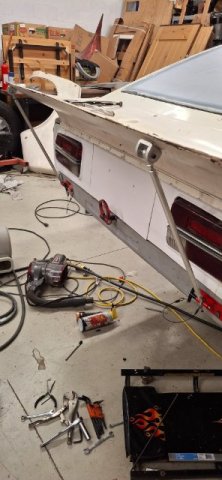
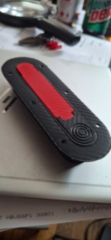
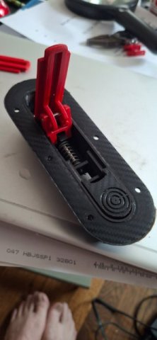
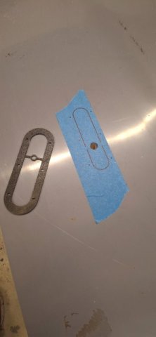
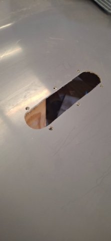
My custom made 3d printed aero hood latches are mounted.
-
IMSA GTU vintage racer build
clarkspeed replied to clarkspeed's topic in S30 Series - 240z, 260z, 280z
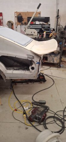
Car is getting some tail tonight!
-
Fast Floridian's 240Z Track Build
clarkspeed replied to FastFloridian's topic in S30 Series - 240z, 260z, 280z
The tranny/rear is a trade off. You really dont want to shift to 5th at 120+mph. The wind resistance will drop you 10+ mph and if you are not in power band you will not accelerate much after that. Not good for Daytona. Rule of thumb is the more peaky your engine is, the closer tranny ratios you need to keep it in power band. The other rule is select gearing to be well into power band or just over in top gear, top speed. Depending on engine you may need a different rear/and or tire ratio to run Daytona, it is different than other tracks. Many club racers run the final 1000-2000 ft at redline, but that can be risky. -
IMSA GTU vintage racer build
clarkspeed replied to clarkspeed's topic in S30 Series - 240z, 260z, 280z
Finished up the 17x8 wheel conversion on a turbo 280z. Got the geometry perfect. All the TTT suspension parts made it easy. https://www.facebook.com/share/p/15JMLRNJpd/ -
IMSA GTU vintage racer build
clarkspeed replied to clarkspeed's topic in S30 Series - 240z, 260z, 280z
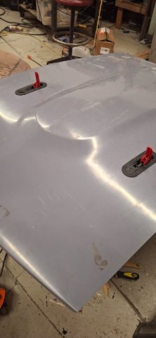
Its already fixed. I have these unusual gnose wide body panels i think are fairly aero efficient. So really the only decisions are if I want to run a cowl induction hood vs. standard no vents. And tall rear 7" spoiler vs whale tail. Input is welcome. Leaning standard hood and big spoiler. Working on mounting these NOW. -
IMSA GTU vintage racer build
clarkspeed replied to clarkspeed's topic in S30 Series - 240z, 260z, 280z
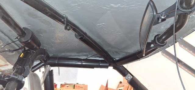
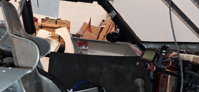
Little safety work ongoing. Finished up the roll bar padding.
-
IMSA GTU vintage racer build
clarkspeed replied to clarkspeed's topic in S30 Series - 240z, 260z, 280z
Got the sensor figured out. It is idling around 130-140 F. Should be OK. I have to post a video. Sorry but I think this thing sounds bad ass. I have an insert in the exhaust so I dont need earplugs. -
IMSA GTU vintage racer build
clarkspeed replied to clarkspeed's topic in S30 Series - 240z, 260z, 280z
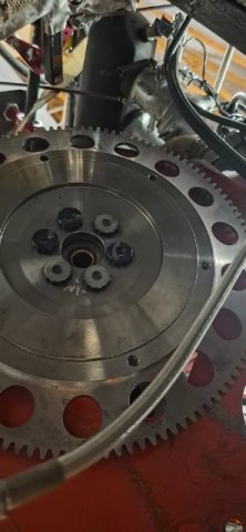
And clutch now finally working as intended. Needed to grind the bolt heads down to 0.200inch to keep from hitting clutch rivets. Now have an overheating problem. But I think it's just a sensor reading wrong. Hopefully easy fix. And a small leak in a water hose fitting. Keep thinking I am almost ready for testing but the hit list keeps getting bigger. More pics coming. -
IMSA GTU vintage racer build
clarkspeed replied to clarkspeed's topic in S30 Series - 240z, 260z, 280z
Yes I have both. And bleeding the clutch is as simple as opening the bleed screw, let a few drips out, and tighten. The thing that takes longest now is removing that giant shifter and the 3 shift rods. And adjusting shift throws when reinstalling. 3 bolts hold shifter and 2 rod ends per shift rod. I can't find a better way to speed it up. AND I cranked the car Saturday and the clutch is close but still not fully released. So another round is coming. -
IMSA GTU vintage racer build
clarkspeed replied to clarkspeed's topic in S30 Series - 240z, 260z, 280z
I am posting this to celebrate my triumph! After full assembly of engine and tranny I could not get the clutch to release. Quartermaster 7.25 v-drive attached to L6 flywheel from TTV Racing. Quatermaster 710 series TO bearing. Chevy clutch disks to mate with 4sp Jericho. QM Button clutches require precise gap from fingers to TO bearing of .120-.150 so I removed tranny multiple times and reset the gap with shims. Everytime I measured gap I got a different measurement. The clutch slipped a little with pedal in but required a breaker bar to rotate driveshaft. Remove tranny, reset gap, reinstall, bleed clutch, check release. After maybe 8 times I stopped and thought about it. Then read directions for the 10th time. Suddenly it stuck out, make sure clutch disk does not interfere with flywheel bolts. I've seen this before. Years ago I ran a similar set up with the head ground down on OEM flywheel bolts. This time I am using ARP flywheel bolts for a RB26. They are 12pt bolt heads already kind of thin, so I didnt consider they could interfere. Well I was wrong. So I ground maybe 0.020" off the head and reinstalled. In the pic you can see marks where the clutch rivet went across the bolts and 3 bolts I have already ground down. On the positive side, I am very efficient R&R the tranny now. Maybe 90min total. And it pops into the pilot bearing like a glove.
-
Building Another Stroker Engine for the Track
clarkspeed replied to inline6's topic in Nissan L6 Forum
Nice work! -
IMSA GTU vintage racer build
clarkspeed replied to clarkspeed's topic in S30 Series - 240z, 260z, 280z
It was a neat circle track solution to a packaging problem. In hindsight I think it added too much weight. May try to redesign way in future. -
Found this on Grassroots Motorsport web page. Seems Legit Garage is adapting some interesting modern trannys to other platforms. Think $2k for a fully sequential used 8sp box, any HP needs you have. The ZF-8HP from BMWs, Dodge and others can be fully reprogrammed for sequential operation and even add a dbw pedal to simulate a clutch launch. Might be a good project for someone that could adapt this to an L6 easily....Derek? Transmission Solutions | "Seems Legit" Garage https://share.google/HyOxohcae82yQu0Th