mjfawke
-
Posts
126 -
Joined
-
Last visited
-
Days Won
1
Content Type
Profiles
Forums
Blogs
Events
Gallery
Downloads
Store
Everything posted by mjfawke
-

Radius Rod Failure @ 180kph
mjfawke replied to Whittie's topic in Brakes, Wheels, Suspension and Chassis
XC Falcon. Haven't tried it myself. And I have a 260Z radius rod sitting in my shed that is bent 90 degree in the middle from a crash. -
First, check the computer for error codes. Then check the fuel pressure. Then look for an air leak. FWIW, having had two MAF's fail, they tend to go intermittent rather than give bad values. Although I have heard of them giving incorrect readings.
-
No plan at this point. Car is coming off the road shortly for some new parts - diff, gearbox, flywheel, turbo, possibly some GTR cams. While the engine is out (broken exhaust stud), I'll R&R the rad and IC, seal all of the openings, then pull out the cardboard for a mock-up. Still trying to find the time to do a CAD/CFD mockup. There was also a good article in a recent Racecar Engineering mag showing differences in flow and pressure distribution through a radiator with ducting - the radius on the entry is very important... And yes - cobwebs. It's summer and the spiders are in full swing. There's a redback (black widow for you guys) or two under the spoiler as well.
-
Finally - a pic of the front. Dual ducts are out, there is no need, as the feed can be taken from above the front bumper. Yes, the car is in serious need of a wash and a cut/polish.
-
goofy idea, fan blades on wheels?
mjfawke replied to TheNeedForZ's topic in Windtunnel Test Results and Analysis
There is a big difference between downforce generation and reducing lift. -
Not sure where you got this idea from - we're talking about restricting airflow into the nose of the car (efficiently, otherwise the full radiator area won't be used). Yes, bonnet vents can work - but look at the air entry size and then think about how big the vents would have to be to vent that much airflow. At best, it's part of the solution. Ducting from the rad to bonnet vents is, I think, unlrealistic - there just isn't enough space to build proper ducts (certainly not in MY engine bay).
-
I'm sure I could waste a lot more time building things which don't work... If I had known the Z had such a problem with trapped air in the engine bay, I would have used an air/water cooler instead of sticking the IC in front of the radiator. Or had the engine moved back to the firewall and routed the pipes differently so I had clearance for the factory fan. Hindsight...
-
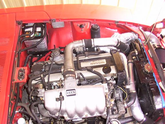
I haven't had time to grab pics from the front of the car yet, but just to clarify a bit, the IC sits in the opening in the radiator support panel, and there is a gap below the bottom tank of ~ 2cm. I'm thinking 2D CFD to look at the interaction of the front bumper, ducting, IC & radiator. Maybe even create a 2D CAD of the centreline of the car to play with front panel work etc. Linux -> Blender (CAD) -> Gerris Solver & Viewer. Here is a pic of the engine bay...

-
No space for a V-config without removing the rad support panel and a major rework of the coolers. My thinking on the two ducts is that it will a smaller overall entry path into the intercooler/radiator than a single duct with only a slightly smaller entry than the intercooler size anyway. Besides which, the bumper sits right the middle and must cause turbulent flow anyway. Less air in a diverging duct should slow the air and make it work more effectively - shouldn't it? And reduce the pressure build up in the engine bay (with appropriate undertray). As background - my car overheats once air temp goes over 32C. Was 28C before I moved the number plate down onto the front spoiler and removed the grill. Main problem is I only have space for thermofans, and they just can't flow enough air. Two years ago I did water manometer testing and the only high-pressure areas were in front of the intercooler and the 2cm gap in front of the radiator below the intercooler. I've been sitting on the issue for two years, because I haven't had time to do anything constructive about it, and didn't want to blow $1KAu on a custom alloy rad. And I cycle to work in summer anyway... I'll dig some pics out later...
-
A duct is an enclosed entryway to the radiator/intercooler, and in the case of what we are all looking at, needs to be smaller at the entry than the exit so that the air inlet area is reduced at the nose of the car but air still flows evenly through the core. Both your and Zr8ed's work aren't ducts, they are just blanking plates around the nose area to stop air leakage. Dragonfly has built an actual duct, but had the angles too steep with the first version and had overheating issues, so had to make the entry larger. 15 degrees is about the maximum divergence angle before flow separates on the walls... ten degrees is supposed to be safer. Two ducts with 15 degrees divergence in the walls will allow an overall smaller air entry area than one duct with the same divergence. I think you should look up the P51 radiator design and the Meredith effect if this is confusing.
-
I'm looking at doing the reduced air intake, and a couple of thoughts. Any angle greater than 15 degrees on the duct is going to cause turbulent flow, which will reduce the effective size of the radiator as the turbulent air around the edges will have trouble going through the rad (actually, intercooler in my case). Given the space limitations, the best solution would appear to be to have two ducts, one feeding from above the front bumper, and one below, both tapered at a max of 15 degrees, and feeding the upper and lower halves of the intercooler/radiator. That way I can have the smallest air inlets without losing out on intercooler/radiator area due to turbulent flow. Thoughts? Note : this is just from eyeballing the front end, I still need to check angles from above/below the front bumper.
-
Student paper on 260Z aerodynamics
mjfawke replied to mjfawke's topic in Windtunnel Test Results and Analysis
Hi Pete! Yes - it's called 'children'. The twins are now two, so I'm starting to have a life again. -
Student paper on 260Z aerodynamics
mjfawke replied to mjfawke's topic in Windtunnel Test Results and Analysis
I'm thinking hood (bonnet) and the lower panel. Anything higher than 10-15 degrees causes flow separation and turbulence, and according to Carrol Smith, not having a radiused entry the the air inlet duct significantly increases the chances of flow separation. Other food for thought - The Electromotive 280ZX turbo had pretty large changes in angles on the radiator inlet duct, but had internal flow guides. Subaru WRX intercooler in stock form doesn't have flow over the front of the IC core without additional flow guides. -
Link here. It's a paper looking at aerodynamics of the SSI Airline Saloon (1934-1935) and 260Z.
-
Riiiiight. Ambiguous use of the 'F' word - would that jut be a serious LOL, or is a friend required? (No reply expected).
-
A slight diversion : I read about this car in a "Car and Car Conversions" magazine about ten years ago. Claimed CD is 0.24. Original car had a massive off around a corner which ripped the driveline out of the car, and was then rebuilt. Web site is here.
-
I'm sorry I hadn't seen your post previously. The rb20det injectors are high-impedance and have no dropping resistor, there are two other dropping resistors - one for the fuel pump, and the auto trans section of the loom has one as well. You shouldn't have had to play with the factory relays - I hate to say it, but there is probably something wrong with the way you have wired up the loom. Have a look for the EGO heater circuit as well - it's not powered by the EFI loom and needs it own connection to the IGN circuit.
-
Just in case you missed it : the heater for the EGO sensor needs its own power feed. The connector which povides IGN & START signals to the ECU also need an ignition switched feed to the EGO heater wire.
-
Mine cooks. I really need to find some time to fit an alloy radiator...
-
wiring a ignition relay required on rb20det in 280z ????
mjfawke replied to twistex's topic in Nissan RB Forum
RB20DET loom requires separate switched 12v for the EGO heater. Goes into the same same plug as the start/ign/tacho wires. As for 12v for your TPS... I don't see how this is possible. -
Yes it's the racing series, Gates Australia had 100 made in Japan. Mate has three spares for his engine, will check for a part number tonight. Otherwise contact Gates Australia and ask about a custom belt for an RB30DE conversion...
-
Best laid plans.... he forgot to mention he was going racing for the weekend, so I didn't pick is up in time.
-
A little late.... The 151 tooth belt used an additional idler on the block. There is a pre-existing 6mm thread which was enlarged to 8mm with a bracket on the top tied to additional points in the block. To use a pre-cast boss on the block drilled/tapped to suit the standard idler requires the block to be at least 10mm, but many of the blocks are thinner than this - his block was only 5.5mm thick, so an alternative was tried. With a 149 tooth belt (which are supposed to be available in automotive grade now), the tensioner is relocated up on the block - once again, block thickness is the issue as to where the tensioner is located. There is a picture... I'll try and scan it in and post it this weekend. Edit: And a link showing how it is done. Depending on the belt used, the idler on the tight side can be changed to a tensioner to allow the correct belt tension to be set. Adjustable timing gear is also mandatory with these conversions to get the cam timing back to where it should be.