
pparaska
-
Posts
5087 -
Joined
-
Last visited
-
Days Won
3
Content Type
Profiles
Forums
Blogs
Events
Gallery
Downloads
Store
Everything posted by pparaska
-
One thing I can't believe no one has brought up is the NHRA rules on "swing arm" axles. Unfortunately, they see anything but a solid axle as swing arm, even though the IRS is better than swing arm. In the older vettes, the halfshaft is part of the suspension (it acts as the upper control arm), and if it snaps, you lose control. It seems that as far back as 1998, NHRA said that many classes of car could not use swing arm rear suspension if the car weighed more than 2000 lb. Since then, I've heard they re-wrote that to allow upper/lower control arm rear suspension for weights above that, supposedly to allow the Vipers to run. Anybody have a 2000 NHRA rule book to check this? Anyway, I've heard of people's quick Z's being banned from a track because they moved into one of these classed (went too quick for their old class) and that rule knocked them out. Any info on this? I'd imagine Michael's car will get into some pretty quick times once he gets the Big Block he wants in it (not the truck motor he has now). I'd figure Ron Jones would know about these things as well. ------------------ Pete Paraska - 73 540Z - Marathon Z Project - pparaska@home.com">pparaska@home.com -
-
Sumo, I agree. For street duty, most old timers I've talked to seem to think 2 bolt is fine. That's what I have, but my engine will probably never see the high side of 375hp.
-
The general advice that I've heard says that unless you are going for much over 400 hp, a 2 bolt setup is fine. The next issue is that there are different "4-bolts". The Chevy 4-bolt block has 4-bolt caps on the center 3 main caps, but the bolts are all parallel to each other. Supposedly, the best way to have 4-bolt main caps is to get a set of aftermarket "splayed" 4-bolt caps and have the 2-bolt block drilled and tapped for the new caps, as the outer bolts go into a beefier area of the block. I don't know if I'd go to that expense on a block that's already bored 0.030" over (is that what you meant?) unless it didn't need any more boring and the clean up hone would not stretch it to the point that new 0.030" pistons would not be a good fit. That may take the bores over the allowed tolerance for the pistons. I don't know if it matters for your application, but some people don't think it's a good idea to bore a 350 block more than 0.030" over if you are trying to get a bunch (450+) hp out of it. The cylinder walls can get thin and start moving around under high hp loads. If you get the block sonic tested, the shop can tell you if it has enough cylinder wall thickness in all areas to be bored to actually be able to handle the overbore without having the walls too thin. Whatever block you get, I'd suggest getting it fully magnafluxed and the cooling jackets pressure tested as well. No sense spending that 2-to-4 bolt conversion money unless you know the block is in very good shape. Hope that helps. What's the consensus here on a overbore greater than 0.040" on the various 350 blocks?
-
WANTED!!! Scan of structural diagram for 77 280Z
pparaska replied to a topic in Brakes, Wheels, Suspension and Chassis
Carter, send the new one and I can PDF it. No Problem. I got a PDF printer driver with the scanner I think. Pretty handy. -
If you want the car to handle my advice is to NOT consider the John's Car's conversion, nor the Hooker engine/transmount/headers for the Z. These kits put the engine in the old "Scarab" position. It's harder to get the car to handle as well with that engine placement than the setback placement that the Jags That Run and MotorSport Auto kits do. It can mean the difference of 4%-5% of the weight being on the front wheels versus the rear. Plus the engine is mounted too high to get a tall air cleaner on it if you use a carb and a high-ish rise manifold. This isn't meant to be a slam to anyone that has that type of conversion, but an bit of info to help V8 Z swap neophytes make a decision. Much of the bad rap the V8Z got in years past was because of the degradation of the handling due to the V8 placement with the old Scarab-type kit/conversion, and the John's Cars and Hooker kits that use the same basic engine placement. If you are drag racing, I don't know if it makes much difference. I believe there is someone one this board that has had both engine placements, and could add some bac-to-back data on this topic. ------------------ Pete Paraska - 73 540Z - Marathon Z Project - pparaska@home.com">pparaska@home.com -
-
WANTED!!! Scan of structural diagram for 77 280Z
pparaska replied to a topic in Brakes, Wheels, Suspension and Chassis
You're welcome! Enjoy, Pete -
WANTED!!! Scan of structural diagram for 77 280Z
pparaska replied to a topic in Brakes, Wheels, Suspension and Chassis
Guys, I played with it a bit (cropped, sharpened, grayscaled, etc.) and put it in PDF format so it will print out on a page of regular paper (tell Acroreader to "fit to page" when printing. It looks a bit cut off on the back of the car, but that's how I got it sent to me. I think all the critical stuff is there. I zipped it up (it was 3.5 Meg uncompressed) and put it HERE The zip file that you'll download is only 130,000-ish bytes. Enjoy, ------------------ Pete Paraska - 73 540Z - Marathon Z Project - pparaska@home.com">pparaska@home.com - -
WANTED!!! Scan of structural diagram for 77 280Z
pparaska replied to a topic in Brakes, Wheels, Suspension and Chassis
Carter, please email the bmp, (zipped or not) to me at pparaska@home.com and I'll PDF it, compress it, put it on my site and email it to Jeff Thanks ------------------ Pete Paraska - 73 540Z - Marathon Z Project - pparaska@home.com">pparaska@home.com - -
Galen, Welcome! I had no idea there were so many modified Healeys! I was really impressed with those. It seems the Chevy V6 makes a nice swap, as your pictures show. One thing on the Z car conversion thing though. This is a personal opinion of mine, but I think others may feel the same way. If you are concerned with handling, stay away from John's Cars conversion if you decide to do the Small Block Chevy. His kit puts the engine too far forward for good handling. The Jags That Run method is preferred by most. [This message has been edited by pparaska (edited October 18, 2000).]
-
Cryogenically treated floorboards and tunnel?! Pretty high tech!
-
Higher Temps Make a Huge Difference!!!!
pparaska replied to Mikelly's topic in Gen I & II Chevy V8 Tech Board
I'd check the mechanical advance curve first, using a timing light and tach. See how much advance past the intiial timing you have at 1600 or so and then decide. You may find that you need to advance it quicker to get the timing a bit more advanced at 1600 than it is now. This is a good way to test for repeatability as well. Do a timing curve test a few times to see if the springs/weights are hanging on some of the tests. I've had a problem with that with the L6 distributors before. -
WANTED!!! Scan of structural diagram for 77 280Z
pparaska replied to a topic in Brakes, Wheels, Suspension and Chassis
Carter, you could run it through a Zip or other compression program and it would get smaller for transport . If Jeff doesn't have broadband, you could send it to me and I could compress it into a B&W jpeg for you and then make a .PDF out of it so that it would print to a page easily. -
Morgan, that's pretty cool . Does it remove the stuff on the underside of the car too? That's what I thought you were referring to at first. I hate that stuff they put on the inside of the floors, etc. It wasn't put down real well in alot of Z's I've seen and a little bit of water gets under it and Whammo! You've got rust BIG time. That's how my floors went.
-
Drilling Rear Flange (4 to 5 bolt)
pparaska replied to PaulR's topic in Brakes, Wheels, Suspension and Chassis
Morgan, I was picturing my car's setup with a 1/2" thick Wilwood Disc hat tha unfortunately does away with any center ring/puck that the stub axles have. So my setup uses only the studs and friction to oppose the vertical shear forces across the flange. Some quick calcs: - (5) 1/2-20 lug studs (large for the sake of an upper bound - I have 4 1/2"-20 studs) - Assume 150 ft-lbs (again, probably high) for the torque spec of the lug nut - coefficient of friction at flange/disc/wheel flange = 0.15 (this is generous, as the surface is uneven and might be greased, etc. Torque = 0.130 * (bolt diamater) * (clamping force) (Design of Machine Elements, M.F. Spotts) Solving for clamping force: (Clamping Force) = Torque / (0.130 * bolt diameter) Clamping Force = 150 / (0.130 * 0.5") Clamping Force = 2310 lbf Times 5 lugs -> 11550 lbf clamping force Friction Force due to clamping of 5 lugs = (coefficient of friction) * clamping force = 0.15 * 11550 = 1735 lbf This is assumed to resist the wheel rotation on the disc/stub axle flange. Assume a 2.25" bolt circle radius Torque to overcome friction = 2.25 * 1735 = 3900 in-lb = 325 ft-lb Well, I guess that with two wheels sharing the load, you'd need 650 ft lbs to overcome the friction due to bolting. But remember how generous I was with bolt size, friction coefficient, etc. If there's dirt or grease on the mating surfaces, all bets are off. Back off to more reasonable lug stud diameter (7/16"), torque (100 ft lb), and coefficient of friction (0.05 - 0.10) and the numbers get down to the a few hundred ft lbs before you over come the friction at both wheel/hub interfaces. I guess I just don't believe that automotive engineers depend on clamping force and friction to take the brunt of the accelerative reactions during take off and braking. But I've been wrong before. There's probably a more accurate way of calculating this, but I'm not interested in looking that far for the truth I guess. You point on preload is well taken. But the head of the lug stud still needs to not pull out. I think your idea of a ring behind the axle or just using large thick washers would work. Welding the area near the edge sounds good also. All in all, I still think the idea of taking the Z stubs and doing the 5 lug drilling is failry sound. The thickness of that flange makes up for alot of the drawbacks of those two studs being near the edge. -
Drilling Rear Flange (4 to 5 bolt)
pparaska replied to PaulR's topic in Brakes, Wheels, Suspension and Chassis
Ya know, this bothered me at first when I heard of it years ago, but considering the forces on the studs will be along the direction of the bolt circle for acceleration (and braking, but that goes from the disk, to the stud, to the wheel mostly) the 1/8" to the outside isn't too much of a factor. As for taking up cornering and dead weight loads, you have 5 studs taking the shear forces all in one direction. The worst case is when those 2 studs that are close to the edge are on top of the axle taking upward vertical loading from the tire, they get pushed towards the outer edge. But the material is thick and the other 3 studs share the load. Other than that there are loads that want to pull out the stud under the weight of the car and cornering, but the flange is pretty thick and a good 80% of the circumference of those 2 studs near the edge are in a meaty area of the flange away from the edge. The above is a mechanical engineer's point of view. I haven't done any calculations to back this up one way or another. I'd love to get some feed back on my thoughts above. I'm beginning to not have a problem with this swap. But just looking at it does make one feel a bit uneasy at first. Of course, racing the setup is the ultimate test. Any data on this? [This message has been edited by pparaska (edited October 17, 2000).] -
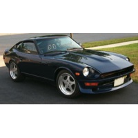
I'm pretty sure this is a 240Z, but I'm not sure.....
pparaska replied to a topic in Body Kits & Paint
It's a 240Z, 260Z, or 280Z. I'd venture it's a 240, but I'm not positive. -
I bet WD-40 would do it. But I'd rather not have a bunch of oily stuff on the sheet metal, as you'll want to put something on it later that would necessitate takign the WD40 off and out of the seams, etc. Mineral spirits or anything like that will work on the tar. Tar will brake down with any kind of petroleum based stuff that comes off the distilate tower above motor oil, I'd think. Ever seen what gasoline does to a tar patch on the road or driveway? I wouldn't use gasoline though, too dangerous. Be careful with any of those solvents, obviously, for your health and fire hazard reasons. Even if you use dry ice, your going to have to clean up the residue on the sheet metal. Clean it with a paint shop metal wipe after getting the residue off with mineral spirits. You might want to etch the metal with something like Oxysolv, etc. to get a nice rough surface for the POR-15 to bite onto.
-
It works, believe me. The heat softens it then you scrape it off like butta. If you heat a 6" by 6" section at a time with a heat gun it will just scrape it off like scrambled eggs. There will be a small amount of residual stuff at the edge of the scraper swipes, but that comes off real easy with mineral spirits. The thing I don't like about the ice method is that you have to hammer the stuff off and ding up the metal with a chisel, from what I've heard. To each his own.
-
Heat gun (or propane torch) and a scraper. Get the residual off with a rag, mineral spirits and gloves. Others use chemicals (not sure, but the really good paint removers supposedly take it off), but I prefer the heat method.
-
Higher Temps Make a Huge Difference!!!!
pparaska replied to Mikelly's topic in Gen I & II Chevy V8 Tech Board
Mike, what's your timing at 1600 rpm? The issue is it's not much probably, unless it has a REALLY quick curve in the weights/springs setup, and you might not want that anyway. The issue is that when you're at 1600 rpm, it might not be getting much advance and that could be causing the lugging, etc. That's cruise condition at those rpm is exactly what vacuum advance is for, as far as my experience and reading goes. Of course, the parameters (air temp, engine temp, humidity, etc.) can make that variable. As far as mechanical advance goes, when a distributor has light springs in it, it can tend to be not too repeatable as to the timing curve from one accuation to the next at low rpm. The trade off in setting this up is balancing the spring tension and weights. Just wondering if this could be a problem as well. I don't know if you've considered any of this, but just in case you haven't, I figured I'd put it out on the table. -
..On second thought, nah you don't want to do the swap. And that engine is crap. Please ship it to me . Just kidding. I'd LOVE to have that engine. You are a lucky guy to have a Dad to find trinkets like that! ------------------ Pete Paraska - 73 540Z - Marathon Z Project - pparaska@home.com">pparaska@home.com -
-
Sam: THe ZZ430 is a SWEET engine. Flat torque curve, lots of torque, excellent driveability, lots of hp. This is what I've read over and over and the numbers hold this out. Ross C can give pointers on how to proceed. Take on Vipers? Well you'd at least be in their league for acceleration. Just use as much pedal as you think you can handle, and learn how to use more slowly. Of course a road course driving school is a great way to learn the respect you seek. Welcome aboard! I say go for it if you can get help from the Dad or any other wrench turners.
-
Companion flange fitting
pparaska replied to alsil's topic in Brakes, Wheels, Suspension and Chassis
As far as my notes go, the 240Z and 280ZX Turbo stub axles have 25 splines and the 280Z stub axle has 27. You wouldn't be able to even get the 280ZXT companion flange started on a 280Z stub axle. The diameter in the splined area is a bit larger as well. The only thing I can think of is a burr, or the 280ZXT companion flange is just at the small side of the tolerance band. -
Front Frame Measurements???? Pete??
pparaska replied to Ray's topic in Brakes, Wheels, Suspension and Chassis
Jeff, when you say 77 280ZX, I get confused. As far as I know, all over the world (even Canada), the Z did not change until 79, when the 280ZX debuted. Until then (through 78) it was a 280Z, except for places like UK where they kept calling it a 260Z. Did Canada actually get a 280ZX in 77? Either way, I'd think the dimensions are different for the 77 280Z from the 240Z dimensions I posted. They changed alot of things in that time span. Hopefully, someone can do a high res scan of a structural diagram from a Nissan 280Z manual for you. If you car isn't too tweaked, why not measure it up and put it on CAD? I did that in order to print out some drawings with diagonal measurements of the suspension pick-up points (taken with a plumb bob, tape rule, levels, etc.) in 3D to see what I was working with and how I should move things around to make everyting symetric (to get away from build tolerances and any banging the car might have gotten. -
I think it was Andrew Bayley that ended up adding short legs to the cross bar so that it could be installed behind the roll bar. I talked to Mike Kelly about the width issue. I know what you mean. If you were to cut the ends off the roll bar so that it would sit up on the ledge and angle back enought to not be too near your head, it looks like you'd have to dent or scallop out a section of the inner wheel house to get the bar to lean back enough. Even then, it is wide enough that the ends would be sitting on the forward edge of the raised ledge abive the hole for the seat belt retractors. Mike mentioned that a good welder could take a section out of the center of the roll bar hoop and it would still be structurally viable. I may just do that to get the bar to sit a bit farther towards the rear on that ledge.