vantage
-
Posts
104 -
Joined
-
Last visited
Content Type
Profiles
Forums
Blogs
Events
Gallery
Downloads
Store
Everything posted by vantage
-
Exactly!
-
A gap of .016" is perfect. Ok, here is a third and final test to make sure the HEI module is really defective, if this one won't work then i am quite sure the module is gone. - Connect a 12V bulb or your testlight in place of the coil. When you now turn on the ignition, the bulb/testlight should switch on. - Now engage the starter, the bulb/testlight should blink as long as the starter turns If you need to send back the HEI module, you might want to test your E12-80 module using test steps 1 & 2 from my post a day ago in the meantime
-
Yes, but its a bit more complex The pickup coil creates a small voltage impulse (like an electric guitar pickup), the HEI module receives this signal via G and W, amplifies it using an transistor and then checks when the signal passes zero volt. At that precise moment the HEI power transistor is switched off to open the connection to the coil, which triggers the spark. If you have power on B and C then thats good news as it shows that the module is at least partially functional. Test 2 is testing the same function, but uses a different approach to convince the incoming transistor in the HEI module to trigger the power transistor. Good point. No warranty left on the HEI module?
-
Good, so your power supply to is ok in ignition and starting, and you have the proper +12V on B and grounded the module. As you have already tested the coil for continuity, that just leaves the module itself and ignition triggering for a closer inspection. You won't see a voltage on G and W (except when cranking. and then only a very low voltage, probably below 1 Volt due to the low cranking speed), as the module measures the voltage coming from G and W. No need to worry about this. 1. As the power supply is ok, you should see +12 Volt on the HEI modules output terminals B and C (e.g. the coil) as soon as you switch on the ignition. If there is no output voltage on B and C there is a good chance that the HEI module is defective, but lets see how test 2 turns out. 2. Here is another trigger test: remove the pickup's green wire from the modules terminal G. Connect the wire from your test light to B/coil (+) for +12V. When you now touch the modules terminal G with the test light and then remove the test light, a spark should be triggered (the test light won't come on with this test, don't worry about that). - If you now get a spark, continue to test the air gap as posted by nosebleedZ. - If there is still no spark then your module is most probably defective. Either get a new one or try reinstalling the E12-80 module and do test 2. again. Which HEI module do you use, can you post the brand and product number/name?
-
1. Good, now please test B/coil (+) to ground when cranking, if you then still have +12V the power supply to the ignition is OK! 2. In the current setup with the ignition on (and +12V at B/coil(+)), do you get a spark when putting a wire across red and green? Good luck, Adrian
-
You should ignore w/g and b/w as due to the PO's modification those do not supply the necessary +12V to the ignition system. The diagram is correct, have you been able to do the tests from my last post? (Test if you now have +12V at HEI terminal 'B' when the ignition is on and when starting)
-
You ran ground to 'C' (not 'G')? Please don't, thats the job of the HEI/E12-80 module Ignore the black/white and green/white wire coming from the ignition key as your factory wiring has been modified. Your HEI terminal 'B' must be wired to coil (+) & black/white in your drawing above. Then check the following: - Test if you now have +12V at HEI terminal 'B' when the ignition is on and when starting If you can ensure that you have +12 Volt on coil (+) and HEI terminal 'B' while ignition is on and on starting, then there is a high chance that the ignition will work as expected. Don't forget that the HEI module needs a good ground connection to work.
-
The late 260Z tach is the three wire type which connects to the (-) terminal of the coil. The Megajolt system uses a wasted spark EDIS coil pack, so unfortunately you can't just connect the tacho the same way as with a single ignition coil. Either you convert the 260Z tacho by removing/modifying the incoming signal filter on the tacho PCB, so it accepts the +12V square wave tacho signal supplied by the Megajolt box, or you could use a tacho adapter such as the MSD 8920, which is wired inbetween the Megjolt tacho out and the tach's input wire.
-
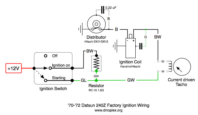
You shouldn't need to go back to points, your pickup coil is ok and it's unlikely that both the HEI module and the E12-80 module are defective, so it must be something basic (e.g. easy to fix) in the wiring The two charts i have posted should help finding the wiring issue, as the PO seems to have messed with the stock wiring. 1. I was referring to Johns wiring chart, where the condenser wire connects to coil (-), and is then repurposed to connect to terminal 'C' on the E12-80, your setup seems to have been modified though. Thanks for the diagram but i have to confess that i still dont grasp what has been changed on your stock wiring. 2. If the green/white wire supplies +12V in ignition and start position (check this with your test light), then that is sufficient for the test. The scope is to rule out the tachometer wiring as a possible problem. Low priority, get back to this when you did the test in the last paragraph was positive Correct, if you can't measure +12V between coil (+) and (-) while the key is in ignition or start position, then the coil won't fire. The reason for this is most probably the missing +12V and ground supply to the coil and/or the E12-80 module. As a simple yet effective test i recommend to connect a 12V bulb (a standard 21W car bulb works nicely, or you use your test light). The bulb should be on in the ignition or start position, and only go out when the coil pickup triggers an ignition, e.g. when turning the starter it should flicker. I know it can get frustrating to search for an electrical problem when you don't have the routine, especially when the stock wiring has been tampered with, but with a structured approach you actually save time and still make sure that nothing is overlooked. Thats the reason for my somewhat lengthy replies Now you should focus on the voltage supply and the correct ground connection to the E12-80 module, as described in my last post. If you can ensure that you have +12 Volt on coil (+) and E12-80 terminal 'B' while ignition is on and on starting, then there is a high chance that the ignition will work as expected.
-
L28 w/zx ign swap in 72.. runs w/key in start position
vantage replied to datjunky's topic in Ignition and Electrical
The wiring chart below might help. Dtsnlvrs is right, in your current setup you probably get power only via the start position of the ignition key, so the engine dies as soon as the key is back to ignition.
-
Got it, the points condenser wire is really the coil (-) wire, that makes sense. I've updated my chart below to show the E12-80 wiring, maybe that makes it a bit less confusing. Getting a light between coil (+) and ground means that the coil receives a +12V supply = good. A light between coil (-) and ground shows that the primary coil is ok (the voltage goes from the (+) terminal through the primary coil to (-)) = good. When you dont get a light between coil (+) and coil (-), even when turning the starter or bridging red and green, then the coil does does not receive any voltage (e.g. ground on (-)) to build up the magnetic field for the ignition spark, this indicates a defect in the E12-80 module, or the module is not properly connected to ground and/or +12V. While the ignition is switched on, can you measure +12V between the modules 'B' terminal and ground? Is the module properly grounded? (probably by connecting to the distributor casing, as there is no separate ground wire). If both tests are ok, with the ignition on pull the wire from terminal 'C' and measure the voltage (or connect a test light) between 'C' and 'B' (or coil (+)). You should see +12V/light, at least when you bridge red and green or turn the starter. If there is no voltage then most probably the module is defect.
-
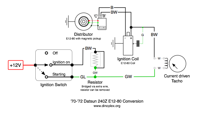
Still following but in a different timezone The E12-80 module would also be my preferred setup. Not sure what you mean with the original distributor wire, if this is the one connected to the points then it would make no sense to connect it to terminal C (coil -) on the E12-80 module. I just checked the wiring scheme again and the only black/yellow wire next to the ignition seems to be the starter wire coming from the inhibitor switch in 240Zs with automatic transmission. Can't remember to have seen that on my '72 US 240Z, i have the following wires coming from the harness at the coil: B (Points), BW (Coil +), GW (Ballast), BW (Ballast). The black/white wire with +12V is routed from the ignition switch via the tach to coil (+), the other one could be the one originally connected to the ballast, but it should have +12V when the ignition is turned on (see image in my last post). The E12-80 conversion should be straightforward, connect E12-80 module terminal 'B' and coil (+) to +12V (supplied by BW originally connected to coil), and module terminal 'C' to coil (-). Good luck, Adrian
-
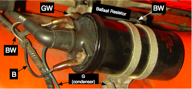
The pickup coil seems to be good, >1Kohm sounds ok. The cable identification is correct, see my chart below. Not sure about black and yellow, should be black and white. The ballast resistor seems to have been removed to always have the full +12V at the coil. This would have overheated the coil and put additional load on the points. 1. Module voltage supply: Do you see +12 Volt when measuring the voltage at the HEI modules ground connector and terminal 'B'? Make sure that the HEI module ground connection is good and there is +12V at 'B' before continuing with step 2. 2. Module trigger: with all components in place, when you bridge the red and green wire going to the pickup coil, do you get a spark then? If you get a spark, then either the polarity of the pickup coil seems to be a problem for this specific HEI module (try to swap red and green), or the pickup coil inductivity and output signal is not compatible with this HEI module, but this is unlikely. If you don't get a spark with bridging the input at G and W, then your module might be defective or the coil wiring is the problem. Do you have the E12-80 transistor module for a test available? 3. Coil: try wiring up a +12 Volt bulb instead of the coil, it should stay on until you bridge green and red. If you turn the starter, the bulb should flash for each trigger. 4. Voltage supply: try a test run without the tacho in line by connecting the green white and black white wire originally wired to the ballast resistor (see chart) to coil (+) and the HEI modules terminal 'B'.
-
Readings jumping around could be a contact problem between the probes and the coils solder pads. If you put the two probes together, you should be able to read 0 Ohm as a quick test. You can get a decent multimeter on ebay, if you spend at least $15-$20. Not sure about the alt light, i don't remember my '72 240Z even having one. 11 Volt is a bit on the low side, you should see 12.5 with a healthy battery and between 12.5-14.8V with the engine running.
-
A test light might not be the correct equiment to check out a coil, you cannot measure a voltage in the pickup coil as long as there is no magnetic pickup inducing a field (and even then, a multimeter or scope would be the better tool). The original black wire from the distributor is connected to the points and switches ground to the coil every time the points are closed, you dont need it in a transistor ingnition/coil pickup setup. The condenser is also only required for a points based setup, a transistor ignition never requires a points or coil condenser. Just to be sure the resistance test is done correct (sorry for bothering you with this), set your multimeter to Ohm/Resistance/Ω and put one probe on the solder pad for the green wire/coil connection (the one on the round plastic carrier) and the other probe on the solder pad for the red wire. The coil pickup should not be connected to the ignition module (or anything else). What does your multimeter show, an open connection (infinite resistance), no resistance (0 Ohm, e.g. a short in the coil wiring), or a value? If your multimeter has different ranges for resistance, you need to set the range to 1-5Kohm. To test your ignition amplifier (the black transistor box) together with the coil, shorten the connection where the red and green wire was connected, if you remove the wire you should see a spark.
-
Rebuilt you say? While you are at it, cut the coils red and green wires where they enter the heat shrink tube and measure again, the external wiring really looks gross. Can you post a photo of the other side of the pickup where the red/green wires are connected to the actual coil wiring?
-
Very good, enjoy. Looks like a compe steering wheel, nice!
-
If a new ignition module wont fix it, have a close look at the ECU injector trigger connection, Coil (-) to pin 1 of the ECU. Loosing that connection (corrosion, vibration) would stop the fuel injection at once, effectively shutting down the engine. What happens to your tach when the engine shuts off, does the needle drop instantly to zero (ignition failure) or does the tach still show the correct RPM while coasting (ignition still runs, fuel injection stopped).
-
With a distributor setup this is a classic indicator to a worn axle which starts to vibrate at a specific rotational speed. With an MJ/MS setup this might be vibrations in the sensor setup, either the trigger wheel or the sensor mount starts to vibrate at 2200 RPM. If you have a scope you might want to have a closer look at the sensor output waveform and timing while running the engine through the problematic RPM range.
-
When you have disconnected everything else, measured the pickup coils resistance via the green and red wire and you don't get a result around 1-2KΩ, then unfortunately your pickup coil is defective. You might want to check if the red or green wire is broken or disconnected inside the distributor. Sounds like you need to get a new pickup coil, unfortunately.
-
So you have disconnected the HEI module from the distributor pickup and then measured the resistance (Ω, Ohm setting) between the distributor pickup wires red and green, and got no resistance, correct? Just making sure, as in one of the last postings you were able to measure 1 Volt, was that also with the HEI disconnected?
-
It's the connection which is the problem. Don't cut into the cable isolation, rather gently remove the crimped connector from the connector housing by inserting a very small screwdriver or pin in the upper rectangle on the front to unlock the connector. Pull it out and solder the red wire from the tach to one side of the crimped barrel, so there is enough space to reinsert the connector back into the housing.
-
Hi Mike, you can test the E12-80 ignition module with the same method (bridging the red and green wire to trigger a spark) to make sure the module itself is ok. The pickup does not require a ground, the induction by the rotating magnetic wheel induces a small voltage which is then supplied to the ignition module via the two wires (red and green). To check the pickup measure the resistance between the (disconnected) red and green wire. good luck, Adrian
-
240z tach and Jacobs Electronics help needed
vantage replied to rackolamb1's topic in Ignition and Electrical
The original tach on a '71 is current controlled, e.g. it is triggered by the current pulse going through the primary coil wire in the original setup. The Jacobs Milemaster works differently as it is a capacitive ignition, sending high voltage (400-600V) pulses to the primary coil wiring. According to the manual (is this the right one? http://www.accel-ignition.com/pdf/341000_372446.pdf) the brown wire delivers a square wave signal to trigger an electronic tacho. You could convert your tacho to accept electronic signals (http://www.dinoplex.org/tachoconversion/), connect your MSD 8920 tach adapter to the brown wire of the Jacobs ignition (see MSD Manual second wiring sheet for current controlled tachos), or exchange your original tacho against a newer one such as made by Autometer and others. -
Correct, If bridging G and W created a spark, you need to check the distributor pickup. A basic test would be to remove the red/green wires to the HEI module and measure the resistance of the pickup using a multimeter on red and green. You should see a reading somewhere around 1000-2000 Ohm. If you dont see a resistance, then the distributors pickup coil is broken, but this happens rarely. A thorough test of the pickup requires a scope so you can see the waveform generated by the pickup when turning the distributor. You already measured a voltage of around 1V (should be a bit less at starting speed though and the multimeter needs to be in AC mode), but i would assume that the pickup is ok when you see a voltage as soon as the distributor turns. A a further test: you could switch the red an green wire to the HEI (red on G, green on W). This just changes the polarity of the output signal, it wont break anything. Be aware that with the wrong polarity your timing will be off, so just use this as a functional test of the pickup/HEI Module.