vantage
-
Posts
104 -
Joined
-
Last visited
Content Type
Profiles
Forums
Blogs
Events
Gallery
Downloads
Store
Everything posted by vantage
-
Excellent! So this test proved that your module is ok and functional! 1. Reinstall the HEI module in the car and wire it to power and the coil. Now, when you do the same test (touch 'g' with a wire coming from 'B') as you did with the successful bulb test, you should get a spark every time. Does that work too? 2. If test 1. was successful, try wiring the distributor green to HEI 'W' and red to HEI 'R' again and turn it by hand (try different speeds, slow and fast), do you now get a spark too? Regarding the Multimeter test, i've checked the manual for your multimeter and unfortunately its missing a low voltage mode (mV or 1-2 Volts), which we need for testing the distributor, so test 2. should be more helpful as we now know that the HEI module is good
-
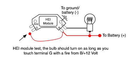
Got hold of a Proform 66944C for testing, the second bulb test i have described works with the module to check its health. Wire it as in the included chart, when you then touch terminal 'G' with a wire coming from 'B', the bulb should flash. Can you do this test and let us know how it turned out?

-
The easiest way to test the spark is to leave it installed to the car, and use a cheap spark tester (two contacts with an adjustable gap). The gap should be set to 2 cm/0.8". The spark tester is directly wired to the coils output and ground. If you don't have a spark tester, you can build your own with some wires, and two screws or nails taped to a plastic ruler. Take care not to get zapped! Now, when running the starter, you should get a healthy, clearly visible yellow/orange spark. If the spark is quite thin and blue, and/or barely visible, your coil might be bad, dwell or the available current voltage is to low.
-
The wiring diagram indicates that either b/w or g/w is life depending on the key position, but when i checked both wires on my '72 240Z it turned out that b/w is life in both ignition on and start key position. You should not put a heavy load on the b/w wire though, as it is directly wired to the ignition key with no relay inbetween. So for my Megajolt setup, i'll use the b/w wire to activate a Bosch 0 332 019 151 SPDT relay via terminal 85, terminal 86 is wired to ground. Terminal 30 (input) of the SPDT switch is connected to battery (+) vi a fuse, the two output terminals (both are labeled 87) are then wired to the Megajolt controller and the coilpack. You could run the fan from the relay described above too, and switch the fan supply off via the g/w wire by using an additional, inverse relay (this type is an closed switch when deactivated). Keep in mind that the fan will start running as soon as you switch to the ignition position, even if the engine is not running yet.
-
I don't see anything unusual regarding the distributor (great photos btw, thanks), looks good to me. The plate is a plastic insulation for the coil, makes sense to have that in place. You don't need a drill, just give the distributor axle a quick spin with your fingers, that should be enough to get a result. BTW, will get a Proform 66944C for testing end of this week, then i'll know more how it should behave
-
There is a very good chance that the distributor is the main problem in your ignition setup based on the results of the latest tests you did. Lets ignore the HEI module for now until we can be sure that the distributor pickup is doing its job. The main problem with the magnetic trigger in the distributor is that you would need specialized equipment to do a thorough test, e.g. a scope would be ideal to see whats going on. Do you have an electronics shop/radio repair shop in your area, which could help? The distributor test with a scope is quite simple, connect the two wires of the pickup coil to the scope's test wires, and turn the distributor axle by hand. If scope's screen shows a "square wave" or "triangle shape", then the distributor is ok. If you just get a flat line, then its broken. If you don't have access to a scope, then here is a cheap homemade workaround test. Buy a cheap red LED at an electronics or parts store, should cost only some cents. Wire the long terminal to the red wire and the short terminal to the green wire. Now turn the distributor axle by hand, start slowly and gradually get faster. The LED should start to flicker at some speed (do this in a dark room, not in the bright sunlight). If the LED does not flicker even if you turn the axle quite fast, then the distributor coil does not get a magnetic field, e.g. the coil/magnet needs to get replaced or reassembled properly. I would happily test all your ignition components, but sending them across the globe is unfortunately not very ecomonic. Maybe a forum member with the right test equipment lives next to you and can lend a hand? You mentioned that the distributor has been refurbished, do you still have a warranty in place? Then the problem of testing and fixing the distributor could be delegated back at the seller.
-
Aha! Test 1 would explain why both the HEI module and the E12-80 did not work. You have checked the resistance of the coil, so the coil itself is ok but there seems to be something wrong with the magnetic components, which create the output voltage. The metal plate you mentioned before might be the problem, could you remove the plate and do test 1 again?
-
Mike, the test 1 is just with the distributor pickup connected to the multimeter. 2a/2b would indicate that the HEI module is broken, maybe the dealer accidentally send the same module back? It is highly unlikely that both tests would not work with a functional module. I am very sorry to hear about your situation, wish you good luck and may things get better for you soon! Best, Adrian
-
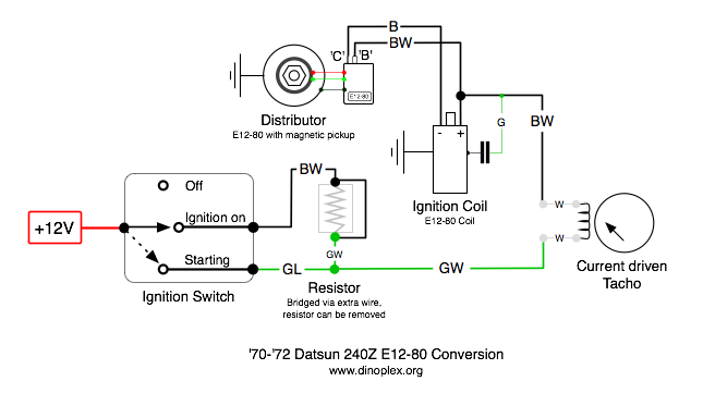
Based on your drawing i would suspect that there are two +12V wires (b/w 12V key and yellow 12v cranking power) connected to the two coil terminals, so whats missing is the switched ground coming from the transistor ignition. I have no experience with the ZX Turbo engine and wiring so am not sure about the wire colors. Please see the ZX280 E12-80 wiring attached below for an example of a correct coil wiring, the (+) terminal of the coil is wired to +12V coming from the ignition key (start and run position, the later one via a ballast resistor), the (-) coil terminal is wired to the output of the ignition module. You need to make sure that the output of the ignition module (which is probably installed on the distributor body) is wired to the (-) terminal of the coil and the (+) terminal of the coil is wired to +12V coming from the ignition key. The little spark blib you see is most probably induced by a potential difference as soon as you turn off the starter, this is not an indicator that the coil is defective but a side effect of the current wiring.
-
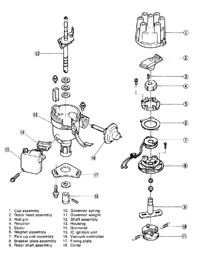
So you have tried two HEI modules and one E12-80 module without success, i think we need to take a closer look at the distributor too. I have attached an exploded view of the 280ZX distributor so you can check if the thin metal plate you mentioned is correctly placed. Two tests to check if the distributor or the HEI module is defective: 1. If you set your Multimeter to measure AC voltage (lowest range like 10 Volt or less) and connect the black wire to green of the distributor, and red wire to red of the distributor, you should see a small voltage (around 0.5-2 Volt) as long as you turn the starter. If there is no reading at all (still 0 Volt), then there is something wrong with the distributor and pickup. Please repeat the bulb test from my last post, but this time do not connect the distributor to HEI 'R' and HEI 'G', but: 2a. instead use a short wire to connect HEI 'R' to HEI 'G' several times, does the bulb blink each time? 2b. If 2a. did not work, touch the HEI module 'G' terminal several times with a short wire which is connected to battery (+), does the bulb blink now? Best, Adrian
-
Can you post a photo or a drawing of the distributor/ignition wiring?
-
You don't need the coil for this test, just remove the two existing wires from the HEI terminal B and C, then connect battery (+) and the testlight exactly as shown in the chart
-
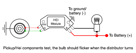
The image i have attached to my last post should explain everything. Wire battery (+) to HEI 'B' and the testlight, and the other side of the testlight to HEI 'C'. When you turn the starter, the bulb should flicker. Normally the bulb goes on as soon as you put +12V on B and the testlight, but that depends on the HEI module.
-
Thanks for the photos! So you have a four wire tach, which needs to be wired inline with coil (+) and the ballast resistor or black/white coming from the ignition key, if you drop the ballast resistor. (See the wiring diagram in my post #26). Lets fix the tach wiring after you got the HEI up and running. The direct wire to the battery test is to rule out any issues there might be with the b/w and g/w wire supplying the +12V to the ignition and just focus on getting the HEI working with the pickup. If this setup does not work, try to reverse the pickup wires, e.g. red to Hei 'G' and green to HEI 'R'.
-
Found something interesting about AC Delco Iridium Plugs
vantage replied to EZ-E's topic in Ignition and Electrical
Iridium/paladium/platin plugs are so called "fine tip" plugs, and help considerably with lowering the spark voltage for the initial spark due to the finer tip. Longevity is a feature you get with the precious metals used, but the main point to use fine tip plugs is that they help a lot with cold and warm start, even when running considerably lean or rich. They don't add performance even if marketing would like you to believe you this. I recommend NGK BPR6EIX if your 240Z has points or a transistor based ignition (280Z/E12-80, HEI, Pertronix etc), the difference in starting or running cold is noticable. Do not use fine tip plugs with an MSD or Crane box, the additional power of the CDI box just eats up the fine tips and with a CDI ignition you don't need fine tip plugs anyway. -
I would suspect that the HI-6 does not get a trigger impulse from the Unilite distributor, that would explain the LED staying on (it will switch off for each trigger impulse received). You can test the HI-6 by touching ground with the white wire (points), each time you do that the LED will go off and you'll get a spark. Disconnect the Unilite distributor before doing this test. I have no experience with Unilite distributors, so can't recommend a testing procedure for checking it.
-
How do I hook up an MSD ignition to a points set up?/
vantage replied to ZPIT U OUT's topic in Ignition and Electrical
If your distributor has a red and green wire coming out of the unit, its a 280ZX distributor with a magnetic coil pickup. Connect the red wire to the MSD's violet wire, and the green wire to the MSD's green wire for a magnetic pickup setup. -
The third b/w wire would be the voltage feed for the throttle opener relay, correct. I am not sure about the tach in the wiring diagram, this is the old type (four wires) and your '73 Z should have the newer type (three wires). The '73 diagrams don't seem to have been updated to reflect this. With the four wire setup, the voltage supply is routed through the tacho, with the three wire setup, a wire (green?) from the tacho is connected to the coil (-) terminal. 1. Could you remove the tach by loosening the two wing bolts on the back and do a photo of the backside/wires? 2. You might want to try this test, remove the b/w wire from coil (+) and HEI module, and temporarily connect a wire to coil (+)/HEI module directly to battery (+). Take care not to create a short circuit. Then try the starter test and check if the test light blinks or if you get a spark. (Do not connect the coil king wire to the distributor with this test)
-
Converting a current driven tacho into an electronic tacho
vantage replied to vantage's topic in Ignition and Electrical
It does look like a kickback controlled tacho. I have no experience with the 280Z tach, but the simplest approach probably would be to use a standard tacho adapter such as the MSD 8920 to convert the Apexi tach trigger to a compatible kickback ("voltage triggered") signal driving. -
Thanks for the pictures! Just saw that you have a '73 240Z, based on the John Hull charts you were using i was assuming you had a '70-'72 Z. 1. You might have used an incompatible measuring mode on your multimeter. Try this, connect the black wire to the middle COM socket and then set the mode switch to "Ω 2.0K" (two positions clockwise from the setting in the photo). What resistance do you get in this mode when measuring the pickup coil? 2. Your wiring looks correct on the photos! It would be good to have another look at the +12V (b/w wire) supply, as everything else looks good. You have posted that you have 12 volts on B, could you also measure the voltage between B and ground while cranking? 3. Could you try to do a photo of the backside of the tacho while it is still installed? (No need to remove it) Would like to find out if its the three or four wire type, that will help in the wire identification P.s. from what i see in the '73 manual, the original wires would be like this: Black/White #1: +12V from ignition switch to ballast resistor (currently connected as +12V supply to coil(+)/HEI module) Green/White: from ballast resistor to four wire tacho (disconnected) Black/White #2: from four wire tacho to coil (+) (disconnected) Black: from distributor/breaker points to coil (-) (disconnected) Black/Yellow: to throttle opener vacuum control solenoid (disconnected, solenoid missing in your car?) Green: no idea yet
-
Good input! For the SBC you need to tap all four coils, the chart only shows two coils as example.
-
Don't worry, your wiring is correct, the HEI module only needs the hot wire and ground as supply! The black wire coming from the distributor/breaker can be ignored. The second chart is also correct, its only missing the ground connection to the module and the ignition/start wires from the ignition key are wired together. The next test now should be the one with the test light wired in instead of the coil, turning the starter should result in the test light flickering. If your HEI module has a current control feature (such as newer Bosch modules), then you won't see the test light coming on before the first impulses from the distributors magnetic pickup, so turning the starter for at least 1-2 seconds should give you real feedback.
-
Good luck!
-
280zx distributor and MSD-6A without E12-80?
vantage replied to BTF/PTM's topic in Ignition and Electrical
Just wire the magnetic pickup coil's output wires to violet/green of the MSD 6A, thats all. -
Yesterday you mentioned that there was power between B & C (coil terminals, test 1.), did something change between the test or typo? Just want to be sure i don't miss anything