Chickenman Posted August 2, 2017 Share Posted August 2, 2017 I found a couple of Plastic adapters at Home depot. Best choice seems to be a 1/2" NPT PVC reducer bushing. Schedule 40 so should be good to 200 F. 48 cents each... so I think I can afford a few mistakes!! Found some PTFE reducer bushings ( For Chemicals ) at McMaster Carr that are good for over 400 F. $37.00 each!! Quote Link to comment Share on other sites More sharing options...
madkaw Posted August 2, 2017 Author Share Posted August 2, 2017 I'll let you know if the nylon experiences meltdown -lol Quote Link to comment Share on other sites More sharing options...
madkaw Posted October 16, 2017 Author Share Posted October 16, 2017 Well on to IAC . Car is running fantastic but it's starting to turn cold and start ups might need a little assist. I am going with the 4 wire IAC from the Jeep 4.0 DIY Tune makes a block for mounting the IAC valve . New Borg Warner selonoid is about 45$ and pigtail is 18$ at your local Oreillys . So far - besides pulling wires- the hardest part was figuring out a mounting bracket and a place to mount . Didn't want to drill holes and it has to somewhere to make running vacuum lines handy . Plus this hunk of aluminum is big! Right now my question that bugs me is whether running these wires close to my sensor wiring is going to cause noise. It sure would be handy to run the wires there, but so far noise has not been an issue and I want it to stay that way. Quote Link to comment Share on other sites More sharing options...
Chickenman Posted October 16, 2017 Share Posted October 16, 2017 I don't think you'll have much issue with EMI from the IAC. ( Sounds like a Michael Jackson song... LOL ). just don't run them the IAC and Trigger wires zipped tied t together or running Parallel for any appreciable length. 2" to 3" separation should be enough. WireCare.com makes products for just about everything.. Put their Flex Shield braided sleeving around you trigger wires and that should be more than sufficient for EMI shielding. https://www.wirecare.com/category/braided-sleeving/metal-shielding Quote Link to comment Share on other sites More sharing options...
madkaw Posted October 16, 2017 Author Share Posted October 16, 2017 Well the trigger wire on the MS3x harness was already shielded . The problem is that I DO WANT to run my IAC wires parallel for packaging reasons . I might be able to minimize this , but the most direct route is with my sensor bundle .Theres a local electronics store down the street ( lucky me), so I might see if they have some shielding Quote Link to comment Share on other sites More sharing options...
Chickenman Posted October 17, 2017 Share Posted October 17, 2017 You could get some 4 wire shielded wire for the IAC Valve ten. Audio quality Microphone cable with twisted wires and shielding would work. Ot put the external sleeve shielding around the IAC wires. You can always. double up on shielding. And it looks cooler than Tin Foil. Military, Aerospace, Audio Recording and Scientific Lab equipment is often double shielded. Quote Link to comment Share on other sites More sharing options...
Matt Cramer Posted October 24, 2017 Share Posted October 24, 2017 The IAC driver is pretty well isolated from the other functions in the ECU. Having noise injected into the IAC wires won't cause any issues for the other functions. Quote Link to comment Share on other sites More sharing options...
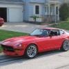
madkaw Posted October 24, 2017 Author Share Posted October 24, 2017 So your saying Matt that my plan is okay to run these IAC wires along side the sensor wires ? I have taken great measure to not have noise issues and so far I have had NO issues with my MS 3 and enjoying EFI life . Very happy to see my plugs looking like this with my 490/290 cam . Engine idles at 800 and has the same power as my triples ! Quote Link to comment Share on other sites More sharing options...
Matt Cramer Posted October 25, 2017 Share Posted October 25, 2017 Yes, that will be fine. The spark plug wires are about the only wires you'll run into that actually radiate noise on a typical motor. Quote Link to comment Share on other sites More sharing options...
madkaw Posted November 9, 2017 Author Share Posted November 9, 2017 IAC made it's first test run today. I have no clue what I am doing as far as adjusting this thing -but have found a few write ups searching . Initially the idle slowly increased as the car warmed up, so I figured it was wired up backwards , so I switched the wires. I think I got that figured but the idle is still too high(2000 rpm). In test mode it showed fully closed on the guage-if that means anything. I guess I should establish whether this valve closes completely when it's closed. With my 240sx TB I have the throttle plate adjusted for idle, so if this IAC doesn't close all the way then I guess that's my issue. I guess I don't know if this IAC had complete control of idle on the Jeep TB's. Maybe my settings are just screwy? Can't stop fucking with it.msq Quote Link to comment Share on other sites More sharing options...
Chickenman Posted November 9, 2017 Share Posted November 9, 2017 (edited) With an IAC enabled you have to physically adjust the TB butterfly more closed than if you run without an IAC. The Jeep IAC is a Stepper motor design and will always be open a certain amount. If it does not receive an ECU command it will default to the last commanded stepper position. Edited November 9, 2017 by Chickenman Quote Link to comment Share on other sites More sharing options...
Chickenman Posted November 9, 2017 Share Posted November 9, 2017 (edited) Good explanation of various types of IAC valves. http://ricksfreeautorepairadvice.com/how-does-an-idle-air-control-valve-work/ https://www.youtube.com/watch?v=oRo5nn9ux1M Edited November 9, 2017 by Chickenman Quote Link to comment Share on other sites More sharing options...
Chickenman Posted November 9, 2017 Share Posted November 9, 2017 Here's some reading to make your Brain hurt. Written for MS2, but should apply to MS3 as well: http://www.megamanual.com/ms2/IAC.htm Quote Link to comment Share on other sites More sharing options...
madkaw Posted November 9, 2017 Author Share Posted November 9, 2017 7 hours ago, Chickenman said: With an IAC enabled you have to physically adjust the TB butterfly more closed than if you run without an IAC. The Jeep IAC is a Stepper motor design and will always be open a certain amount. If it does not receive an ECU command it will default to the last commanded stepper position. This was the big question . I️ know it was partially open , but wasn’t sure that if that was the way it was designed. I️ could pinch the vacuum side and get the idle to come down . Quote Link to comment Share on other sites More sharing options...
Chickenman Posted November 9, 2017 Share Posted November 9, 2017 Yep... with an IAC the TB should just be cracked open. Just enough to prevent the butterfly from being fully closed and digging into the throttle body bore. With a large Camshaft, you may have to crack the butterfly a bit more, as the IAC can run out of available opening range. Quote Link to comment Share on other sites More sharing options...
madkaw Posted November 9, 2017 Author Share Posted November 9, 2017 17 hours ago, Chickenman said: Here's some reading to make your Brain hurt. Written for MS2, but should apply to MS3 as well: http://www.megamanual.com/ms2/IAC.htm Missed that page - thanks . That helps a bunch. Didn’t work with throttle plate closed , so next cold start might get it right Quote Link to comment Share on other sites More sharing options...
madkaw Posted November 24, 2017 Author Share Posted November 24, 2017 AARRRGGHHHHHHHHHH!!!! This IAC is PITA--OMG, ready for the BFH. After getting on the forums at EFI and doing some board changes I got the stepper to operate. Now much of this was my fault because I had a broken pin on my connector and wouldn't you know it was one of the coil sides of this stepper. The guys on the MS forums help me thru that crisis, but still can't get it to operate the way it should. Basically it is working the opposite way I want it too. It idles faster as it gets warmer. Can't tell if it's tuner studio or wiring. I don't think MS does very well explaining things on setting up these IAC's. Jeep IAC madness.msq Quote Link to comment Share on other sites More sharing options...
Chickenman Posted November 24, 2017 Share Posted November 24, 2017 (edited) Just a WAG. But try flipping the Homing Direction from " Closed " to " Open ". Edit: Apparently that's exactly what you do. Quote Fixing common problems Problem: Valve vibrates when commanded to move, but does not actually turn. Solution:One coil is wired backwards; swap wire 1A for 1B, or 2A for 2B. Problem: Valve moves, but in opposite direction of intended. Solutions: Both coils are wired backwards. Switch wires 1A for 1B, and 2A for 2B; With the current firmware, you can simply change the homing direction in the software. Older versions (and original Bowling & Grippo code) do not allow this. Problem: Valve does not move at all on initial power up. Solutions: One possibility is incorrect wiring. Make sure 1A and 1B are on one coil, and 2A and 2B are on the opposite coil; The other usual problem is the time step size is set too small. Try increasing it and see if the valve moves. Problem: Idle speed is not consistent from one start to another at the same temperature. Solutions: Usually, this is caused by the homing steps being set too low. Increase this value until the valve retracts fully; If the valve sometimes retracts fully, but not always, this may mean the steps are small enough that they do not always successfully move the motor. Try increasing the time step size. Problem: The valve retracts normally, but then appears to stop working at some point during operation. Solution: First, check to be sure the algorithm is not set to “15 minute IAC”; this will switch the IAC valve operation mode after 15 minutes, and is only used with a few specific valves that behave differently when warmed up. Next, try increasing the time step size and/or minimum number of steps to move. Some older valves can have problems with stiction. Increasing the time step size will send a longer pulse, while increasing the minimum number of steps to move will send more pulses that can un-stick a stubborn valve. Problem: Idle speed hunts while the number of steps displayed is constant. Solution: It’s easy to assume the IAC valve is responsible here. After all, it’s supposed to control the idle speed, and the idle speed is behaving wrong. However, this is likely to be an issue with the ignition timing or fueling instead. See our guide to idle tuning for details on how to dial this out. Edited November 27, 2017 by Chickenman Quote Link to comment Share on other sites More sharing options...
Chickenman Posted November 24, 2017 Share Posted November 24, 2017 If the above setting change doesn't work, double check the IAC wiring. Quote from the Mega Manual IAC article: Quote Note that if you have the wiring connected incorrectly (or if you don't know how to wire it because it is an undocumented type), wire it up as best you can. Note that you will be able to tell which two wires connect to the same coil by the resistance across those two wires - it will be about 30 to 50 Ohms if they are on the same coil, infinite otherwise. Then try the IAC. One of two things will happen: The stepper motor does not work at all. In this case one of the coil windings has the wrong polarity. To correct this, switch the wires around on either of the coil windings to see if it helps (i.e., trade the connections of the two blue wires). If it doesn't help, switch those wires back and try switching the other winding's green wires. The stepper motor works in reverse, i.e., it retracts when it should extend, and vice-versa. Reverse the wires so that the wires originally connected to: Coil 1, lead A is now connected to Coil 2, lead A, Coil 1, lead B is now connected to Coil 2, lead B, Coil 2, lead A is now connected to Coil 1, lead A, Coil 2, lead B is now connected to Coil 1, lead B. Quote Link to comment Share on other sites More sharing options...
Chickenman Posted November 24, 2017 Share Posted November 24, 2017 Just for comparison, this is the Help file that pops up on my old Haltech E11 when I'm in the Idle Control panel. Some of these explanations may help in setting up your MS3??? Quote Stepper Motor Idle Control Stepper Motor The stepper motor idle control method uses a 4-wire stepper motor with a moving plunger that can alter the amount of air that can bypass the throttle plate. The amount of air allowed around the throttle plate is directly related to the engine speed at which the car will idle. · Enable Stepper motor idle control is enabled if this checkbox is ticked. · Stepper Motor Range The range of steps that the idle motor can move that makes a useful change to RPM. · Cold Target RPM The RPM target that is used when the coolant temperature is below the Idle Cold Temp. · Warm Target RPM The RPM target that is used when the coolant temperature is above the Idle Cold Temp. · Temp Threshold The temperature below which the target RPM used is the value in Idle Cold Target RPM. Above this temperature, the target RPM used is Idle Warm Target RPM. · Cold Open Position The position that the stepper motor will default to when the engine is decelerating and falling toward the target RPM and the coolant temp is below the Temp Threshold. · Warm Open Position The position that the stepper motor will default to when the engine is decelerating and falling toward the target RPM and the coolant temp is above the Temp Threshold. This value is typically smaller than the Cold Open Position. · Post Start Position The position in steps that the idle motor should move to when the ECU is initialised. This value must be less than the Idle Range. This position is held for a 2-3 seconds after starting. · Min Cold Position The minimum position that stepper motor will close to when the coolant temperature is below the Temp Threshold. Set this to a value to ensure that the engine will never stall. · Min Warm Position The minimum position that stepper motor will close to when the coolant temperature is above the Temp Threshold. Set this to a value to ensure that the engine will never stall. · Dead Band The engine speed of a typical engine will vary slightly when idling. To avoid the idle control algorithm over controlling at idle, a dead band can be set so that if the idle is within the dead band value of the target RPM, then no control will take place. Typically, a value of 50 – 60 RPM allows for stable control. · Air Con Steps Increment This sets the number of steps that the stepper motor will move in the open direction if air-con control is enabled, and the air conditioning is turned on. · Air Con RPM Increment This sets the increase in the target RPM when air conditioning control is enabled and air conditioning is turned on. · Advanced Sensitivity Click on the Edit button to open the sensitivity adjustment window. The following steps will guide you through a method to setup and tune your idle control. 1. Ensure that your Fuel and Ignition maps are well tuned and warm your engine up to operating temperature. Block all the idle control orifices, or alternatively, close your stepper motor by setting the Idle Range to zero, and setting the Idle Min Open Position to zero. Enable Idle Stepper Control by clicking on the checkbox and setting it such that a tick appears in the checkbox. With the orifices blocked or stepper motor fully closed, adjust your throttle stop so that the engine is barely running. A typical RPM may be 500 to 600 RPM. 2. Make sure that your throttle is properly calibrated so that throttle position in the engine data reads zero percent when you are completely off throttle. 3. The following values should be set by default in your map. The following values are a good starting point to begin tuning your idle control: § Stepper Motor Range 200 § Cold Target RPM 1200 § Warm Target RPM 900 § Temp Threshold 70 deg C (158 deg F) § Cold Open Position 60 § Warm Open Position 50 § Post Start Position 100 § Min Cold Position 1 § Min Warm Position 1 § Dead Band 30 § Air Con Steps Increment 5 § Air Con RPM Increment 100 § Advanced Sensitivity (you should not need to adjust these values to any great degree so do not concern yourself with the following settings if you do not understand them). · Proportional Co-Efficient 150 · Integral Co-Efficient 30 · Derivative Co-Efficient 5 4. The idle control should now respond to changes to Idle Warm Target now if everything is setup correctly. If it doesn't respond, then examine the stepper motor position in the engine data to check if it is stuck at the Stepper Motor Range position. If it is, and the idle speed is too low, then increase the range until the idle reaches an acceptable speed slightly above your highest target RPM. 5. If the engine is cold, setup the Min Cold Position, set a Cold Target that is very low so that the stepper motor position moves to the Min Cold Position. Increase the Min Cold Open Position until the desired minimum RPM is reached. E.g. If I set a target of 900 RPM and the throttle plate is setup for a 500 RPM minimum idle, then it would be desirable to set up an Idle Min Open Position of 5 to make the minimum RPM 800. While the engine coolant temperature is still below the Temp Threshold, give the engine a light rev and watch how the idle speed is re-established. If the engine speed dips excessively before coming back to the correct idle speed, then increase the Cold Open Position . If the engine holds at a high speed before falling to the target idle speed, reduce the Cold Open Position. 6. With the engine warmed up to operating temperature, repeat the above procedure with the Min Warm Position parameter and the Warm Open Position Parameter. 7. When the engine is started, check that the idle speed begins high and falls back to a stable idle speed around the target. Increase the Post Start Position if required to aid in starting. 8. If the idle speed fluctuates or oscillates, reduce the idle sensitivity parameters slowly until the oscillation stops. If the idle speed is slow to reach the target, increase the idle sensitivity parameters slowly until it begins to oscillate, then reduce the values slightly. Quote Link to comment Share on other sites More sharing options...
Recommended Posts
Join the conversation
You can post now and register later. If you have an account, sign in now to post with your account.