toolman
-
Posts
518 -
Joined
-
Last visited
-
Days Won
7
Content Type
Profiles
Forums
Blogs
Events
Gallery
Downloads
Store
Everything posted by toolman
-
From the album: HD FRAME
-
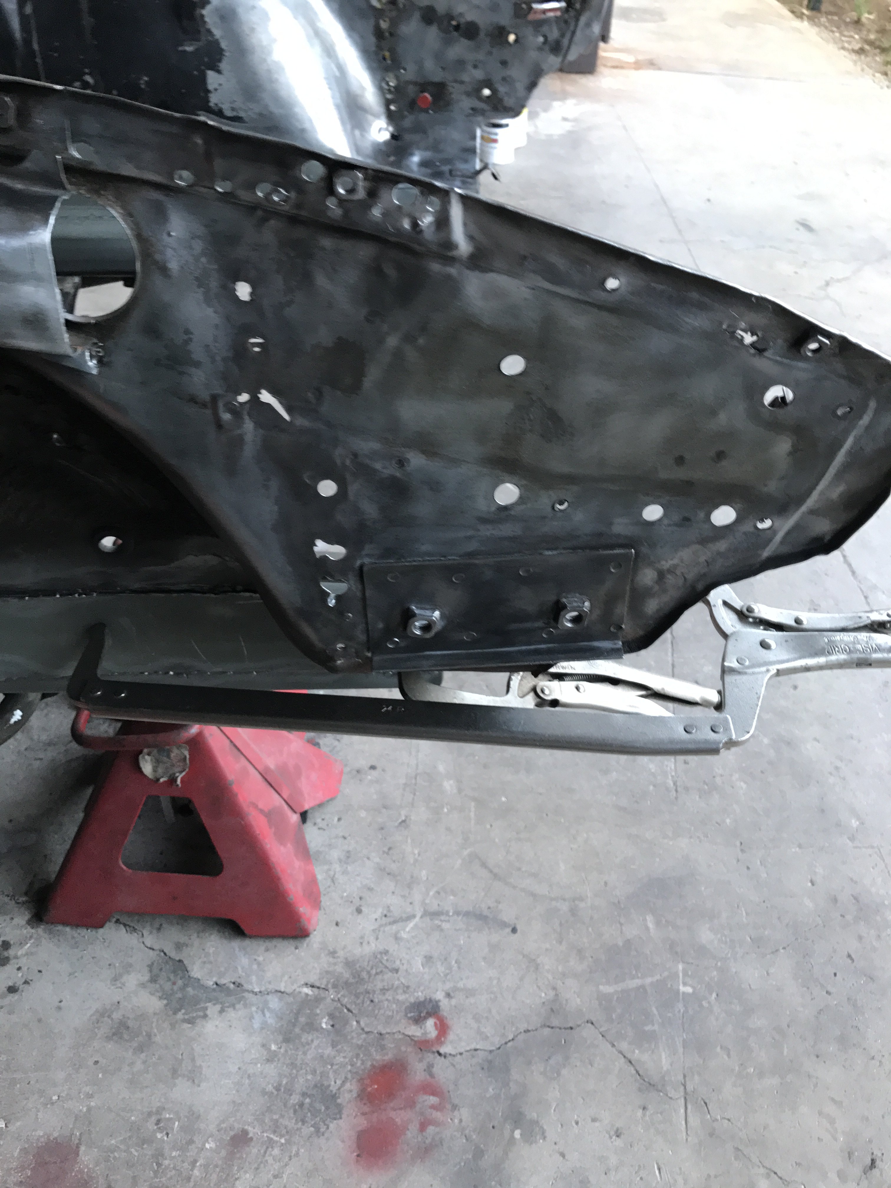
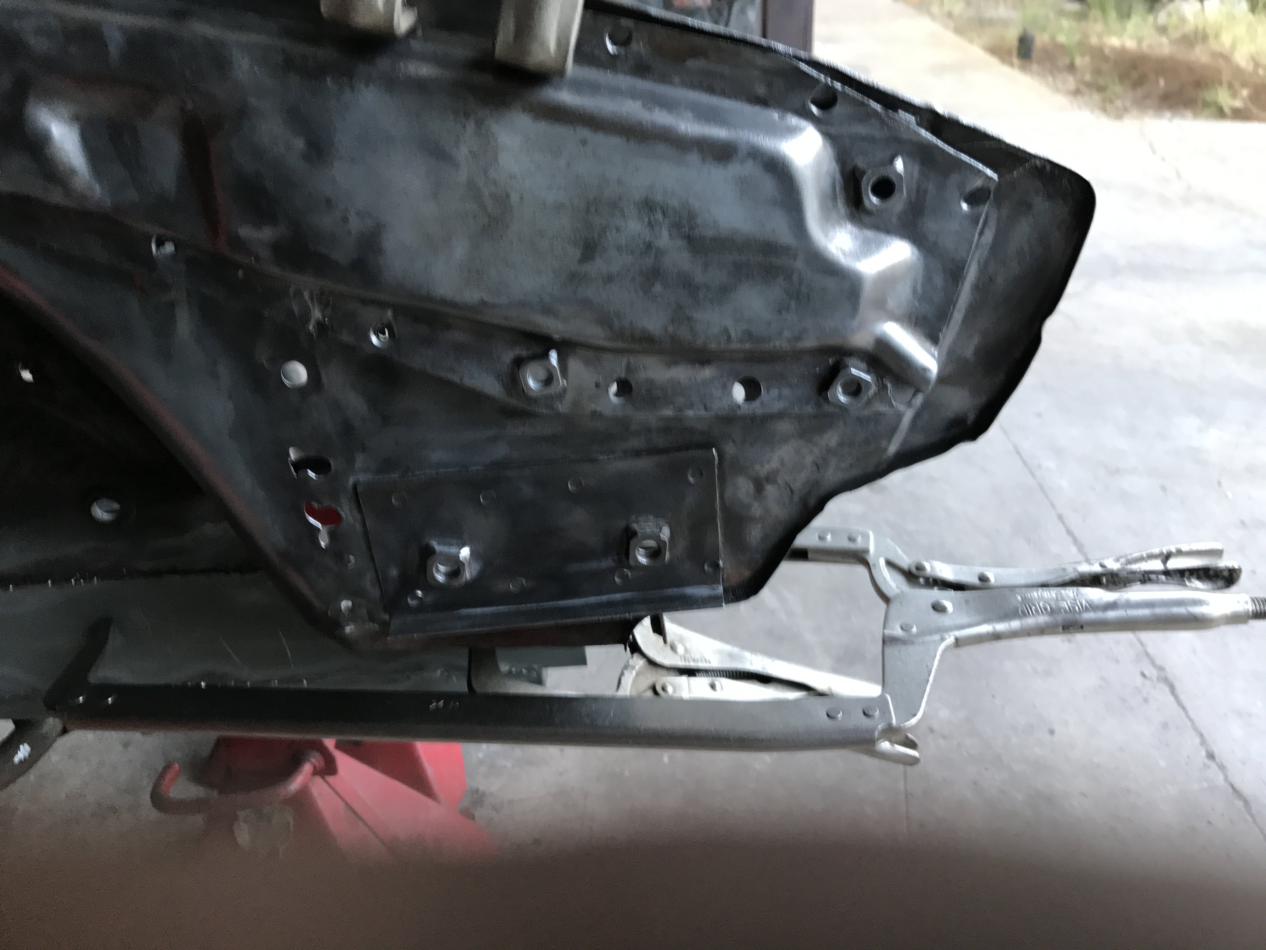
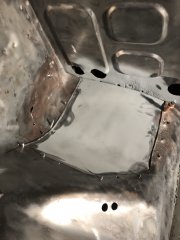
IMG_1831.JPG Replacement patch held in with screws and cleco pins
toolman posted a gallery image in HybridZ Cars
From the album: HD FRAME
-

From the album: HD FRAME
-
From the album: HD FRAME
-
From the album: HD FRAME
-

From the album: HD FRAME
-
From the album: HD FRAME
-
From the album: HD FRAME
-
IMG_1781.JPG Right side replacement section mocked up
toolman posted a gallery image in HybridZ Cars
From the album: HD FRAME
-
From the album: HD FRAME
-
From the album: HD FRAME
-
From the album: HD FRAME
-
Heavy Duty frame rails and connectors
toolman replied to toolman's topic in Gen III & IV Chevy V8Z Tech Board
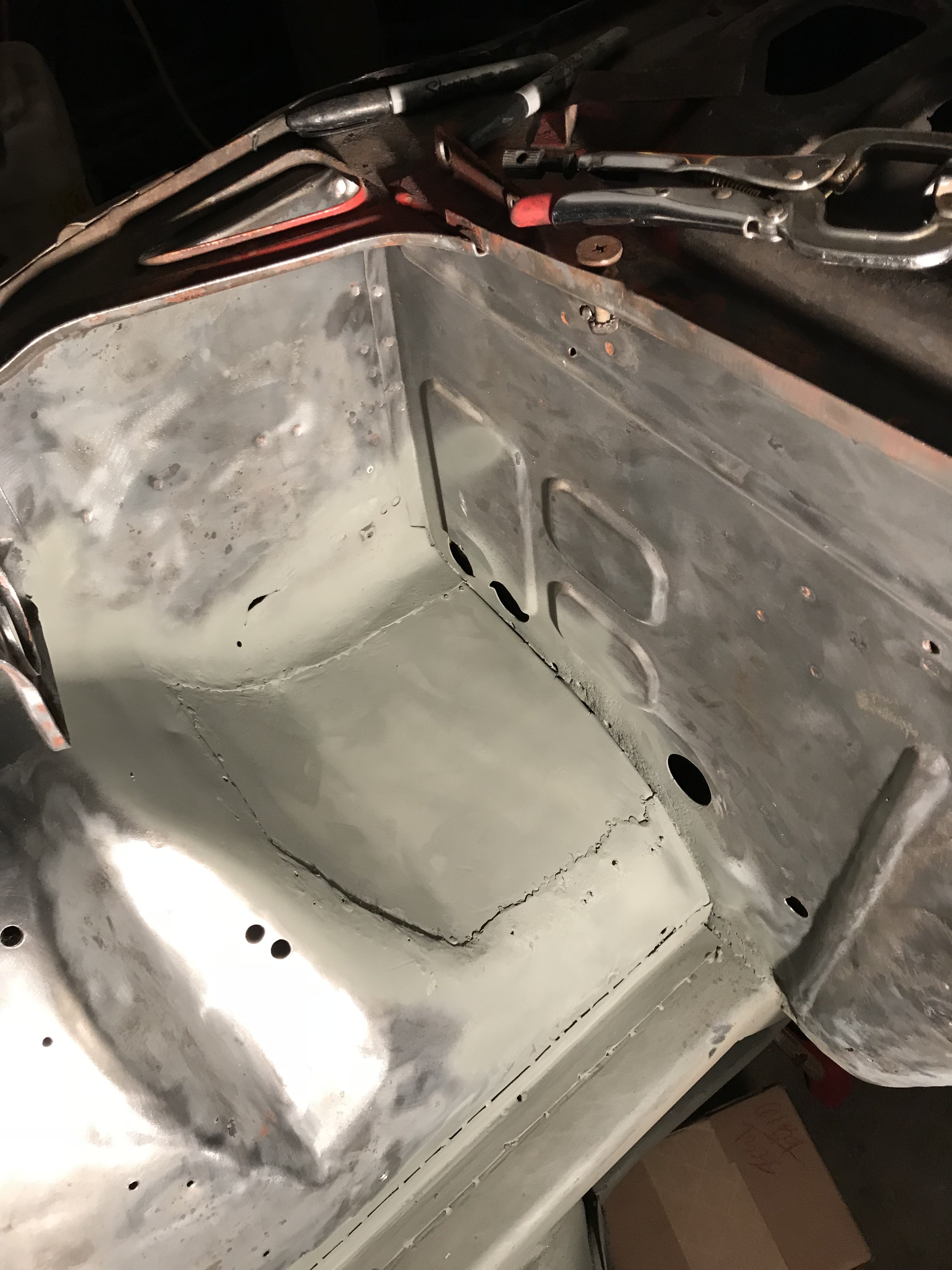
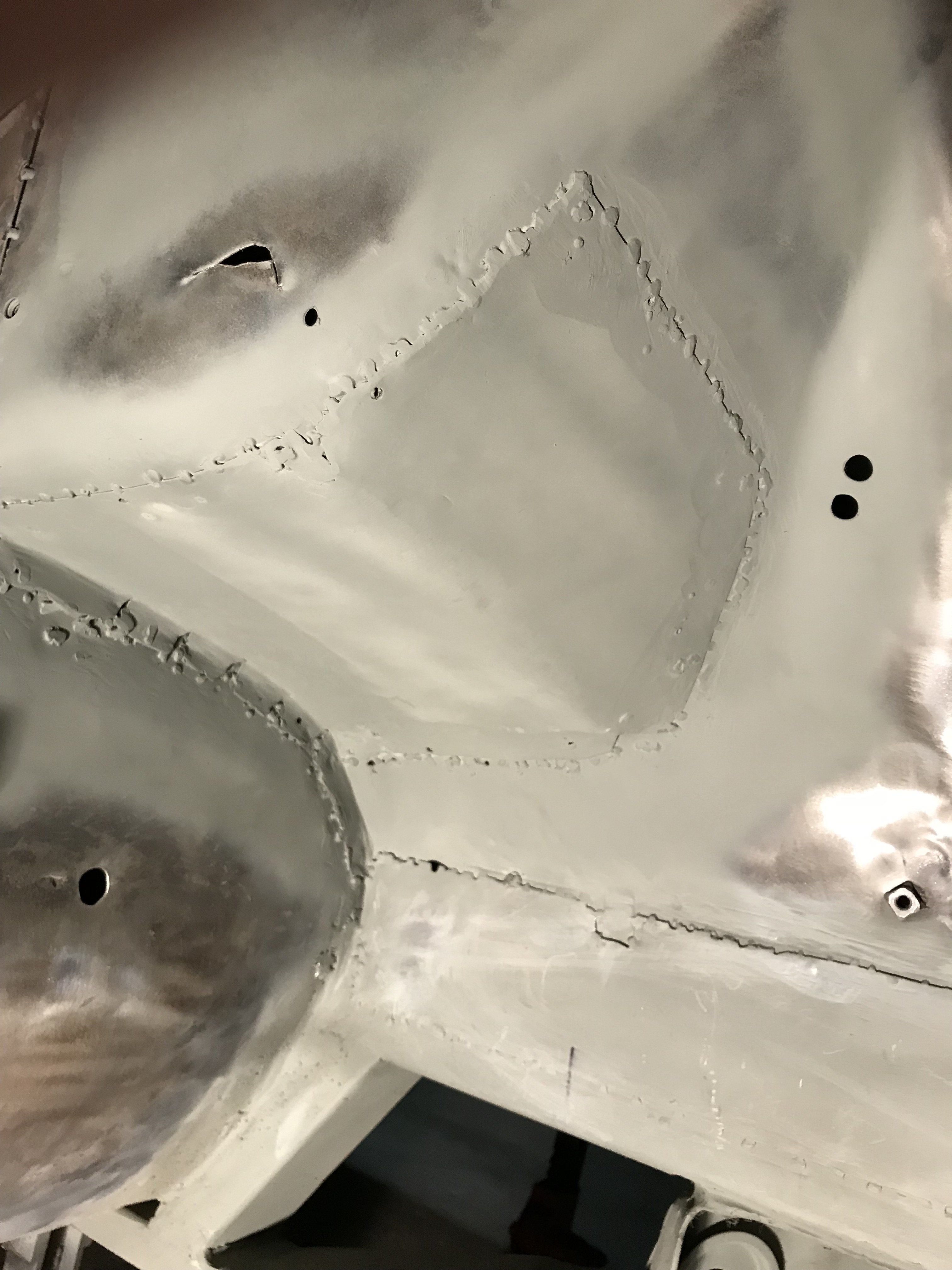
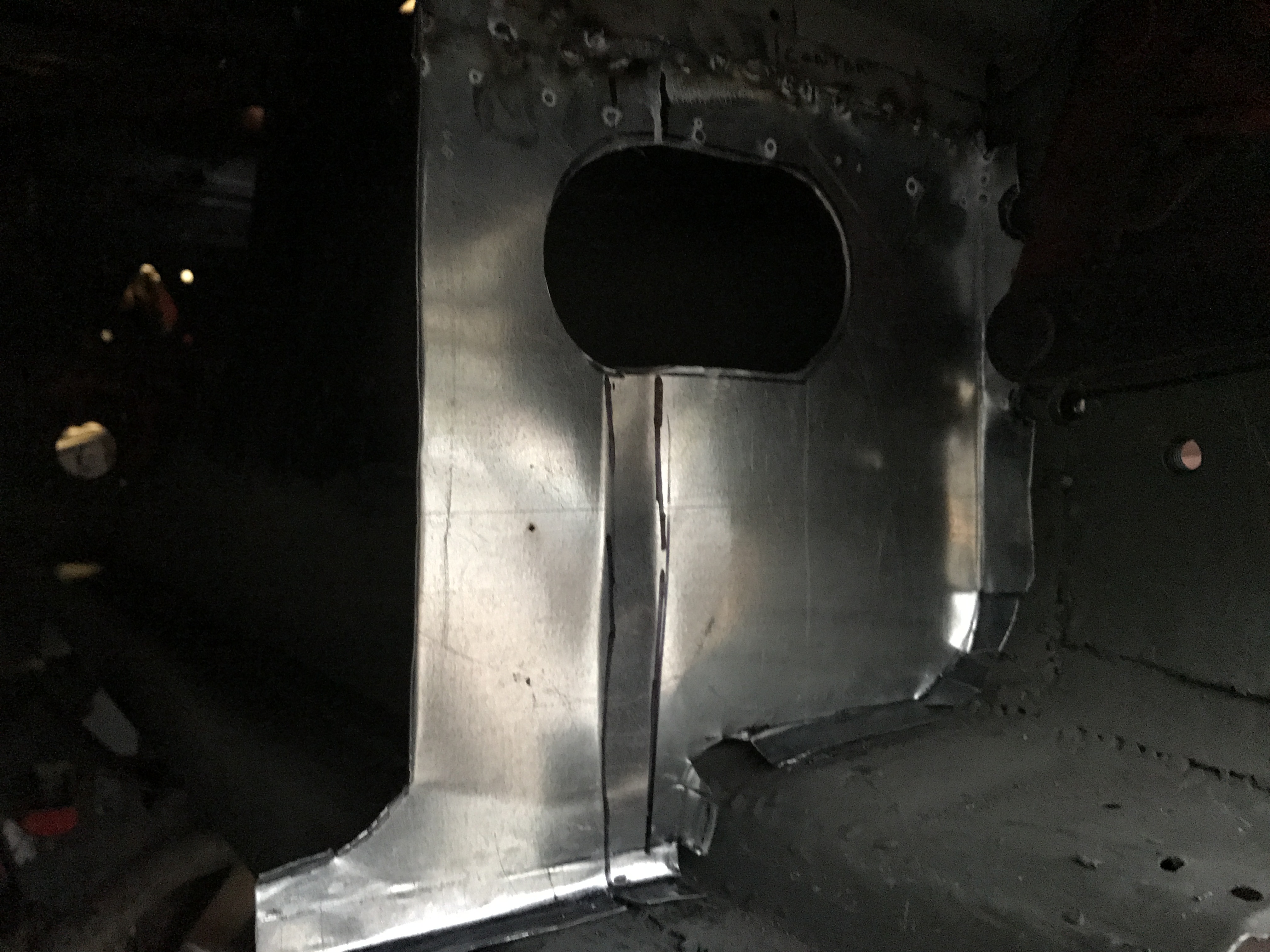
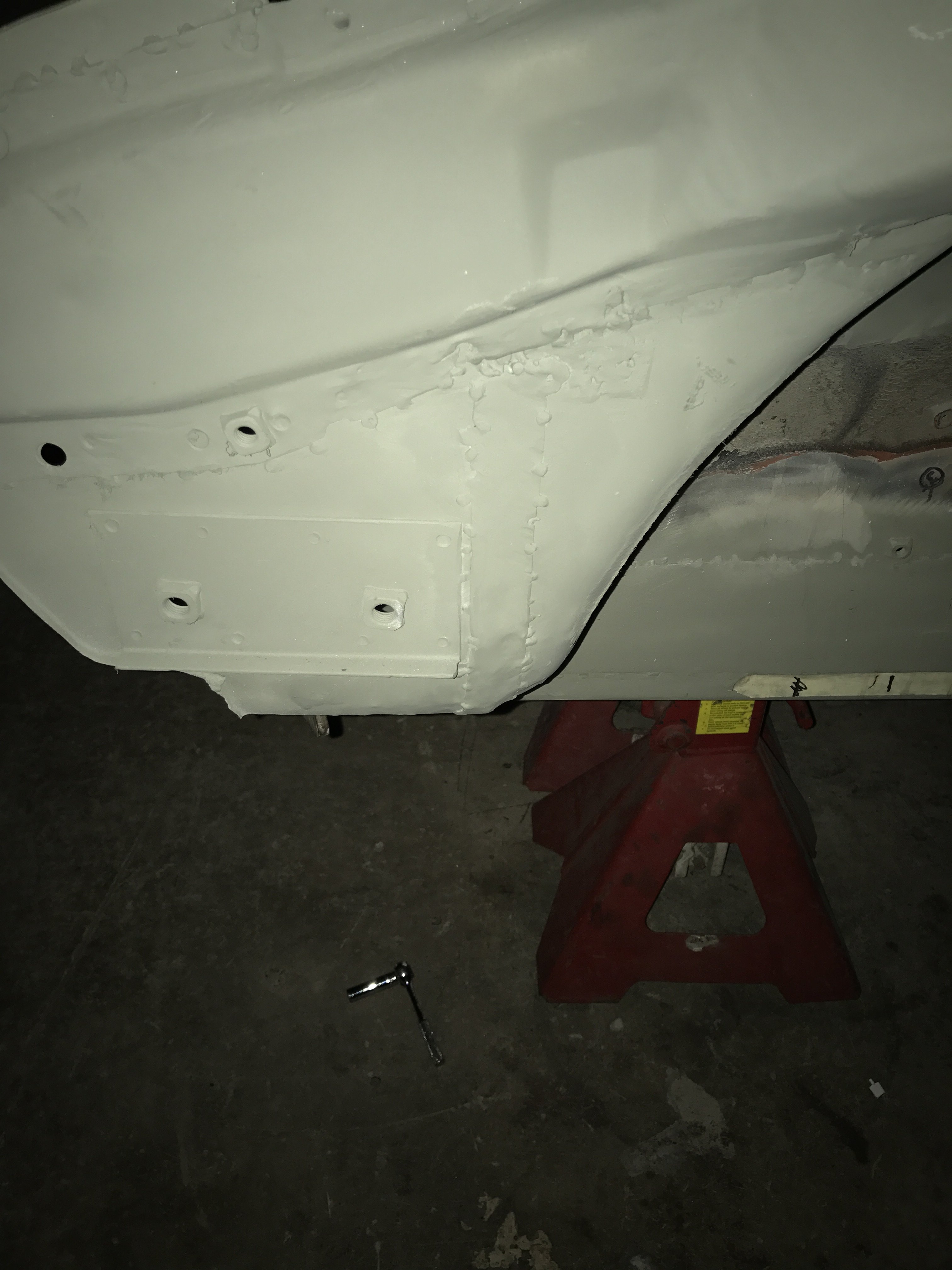
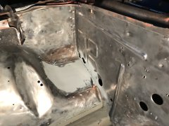
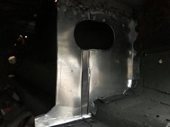
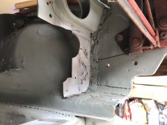
First picture is the top view of the patch welded in. Second pic shows the bottom view of the patch. I have not decided whether to reinstall the battery holder or relocate it to the rear of the car.
-
Heavy Duty frame rails and connectors
toolman replied to toolman's topic in Gen III & IV Chevy V8Z Tech Board
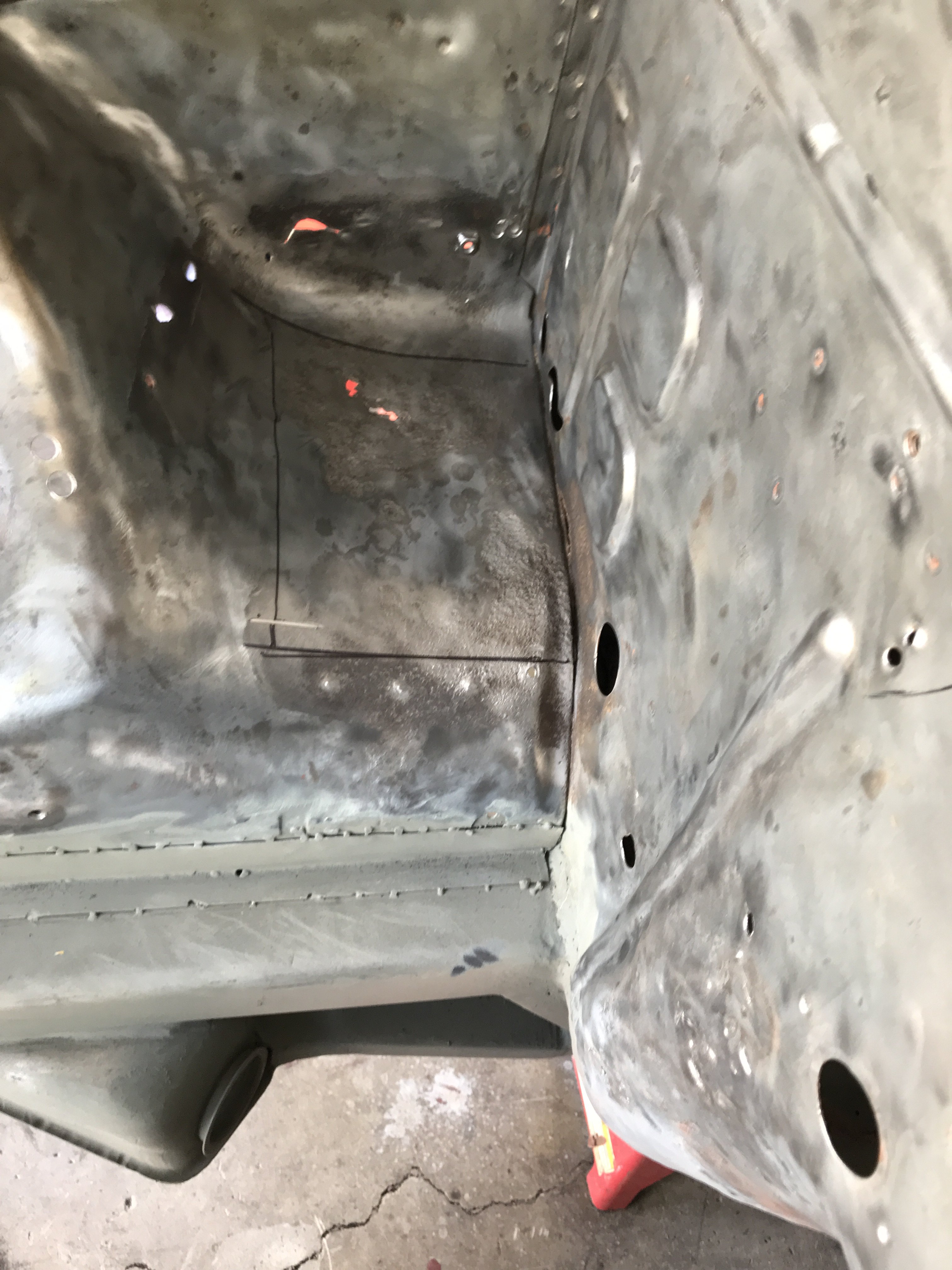
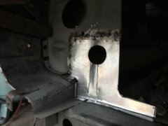
Patch had to be held in place with Cleco clips for welding. Sheet metal screws were also used.
-
Heavy Duty frame rails and connectors
toolman replied to toolman's topic in Gen III & IV Chevy V8Z Tech Board
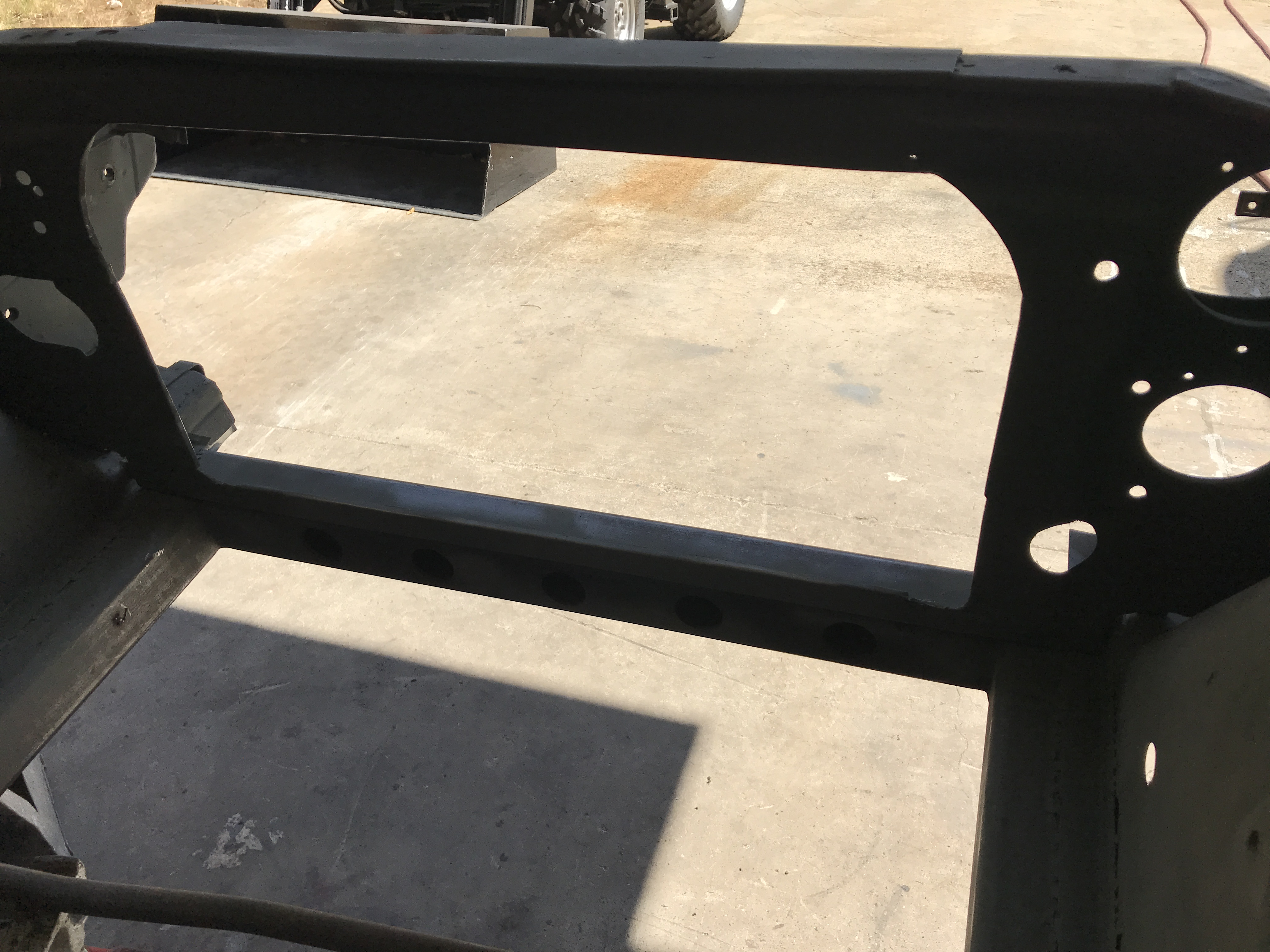
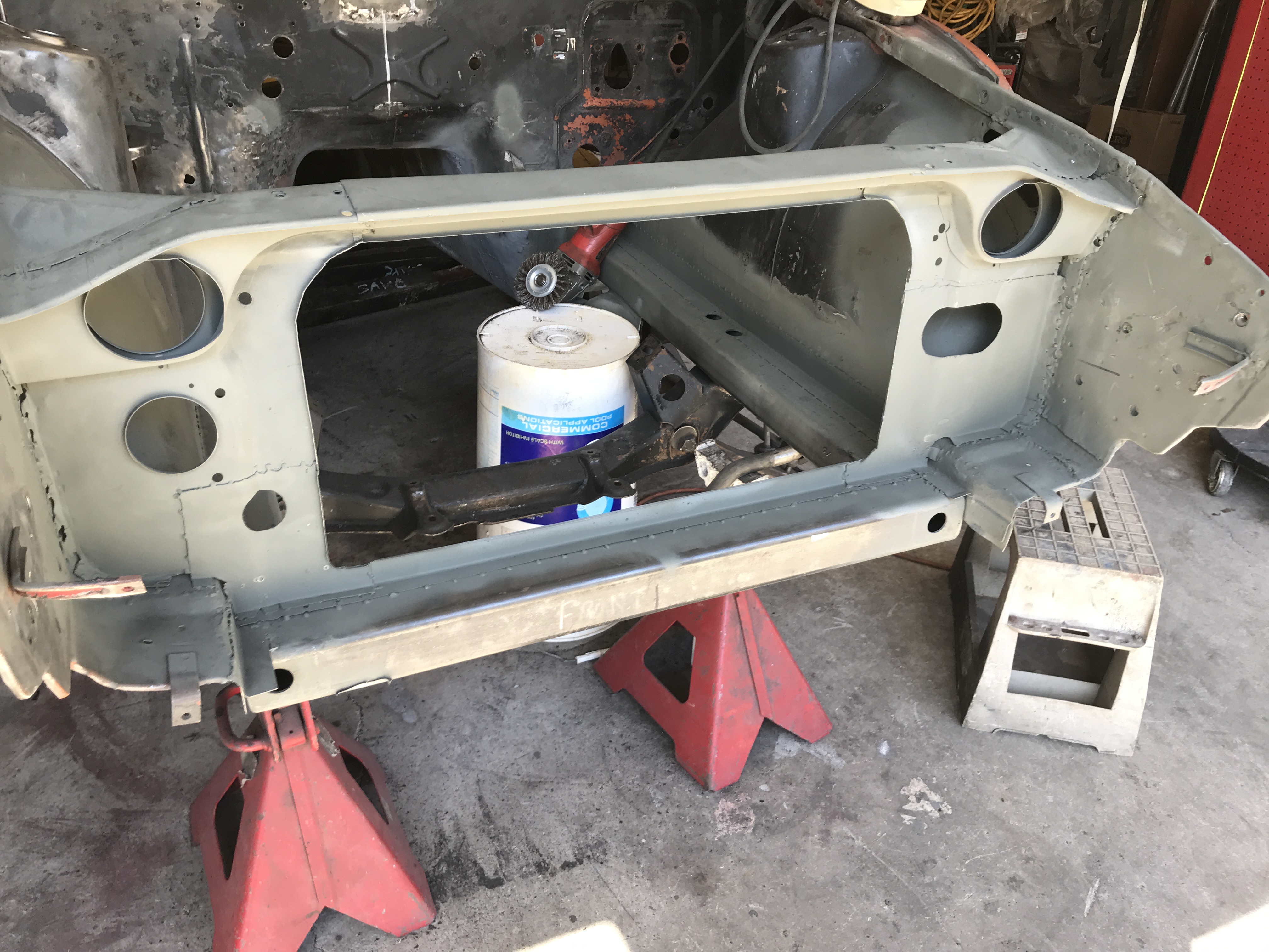
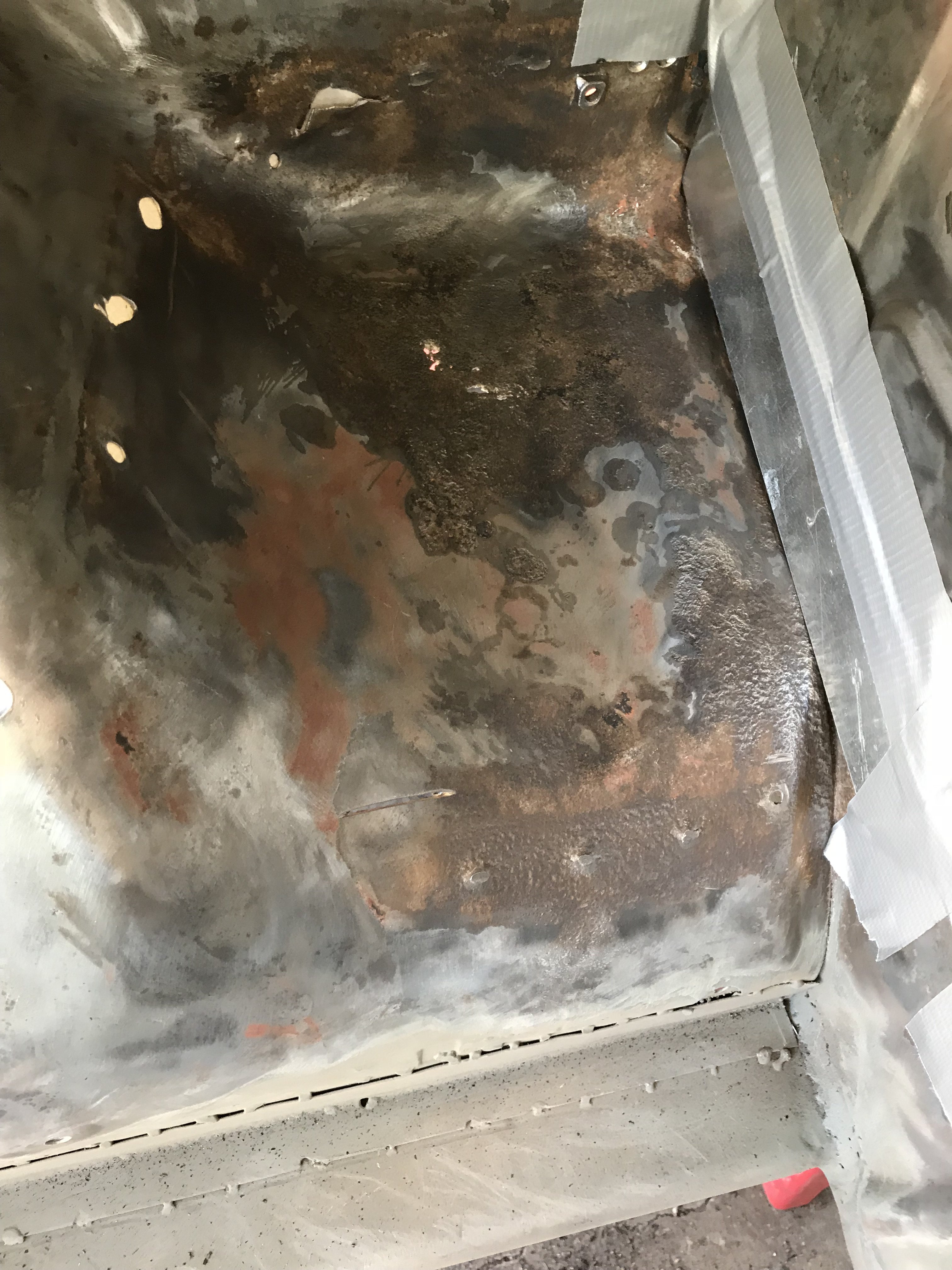
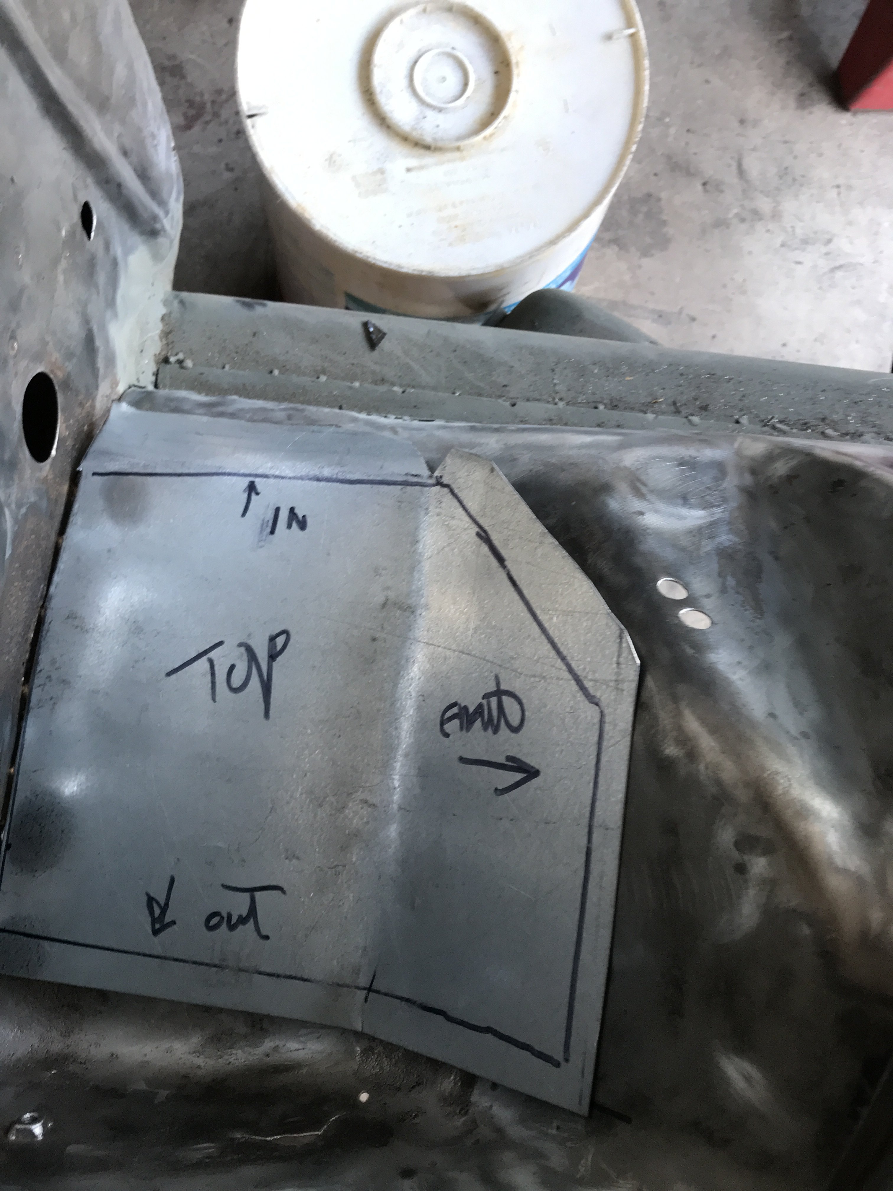
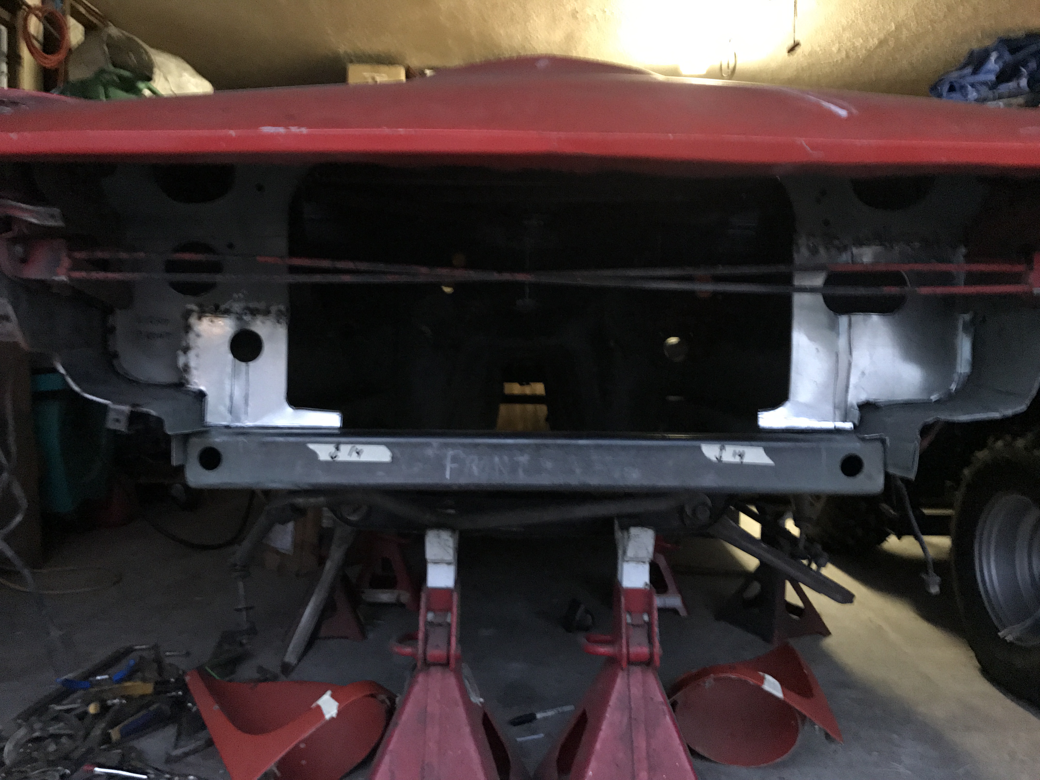
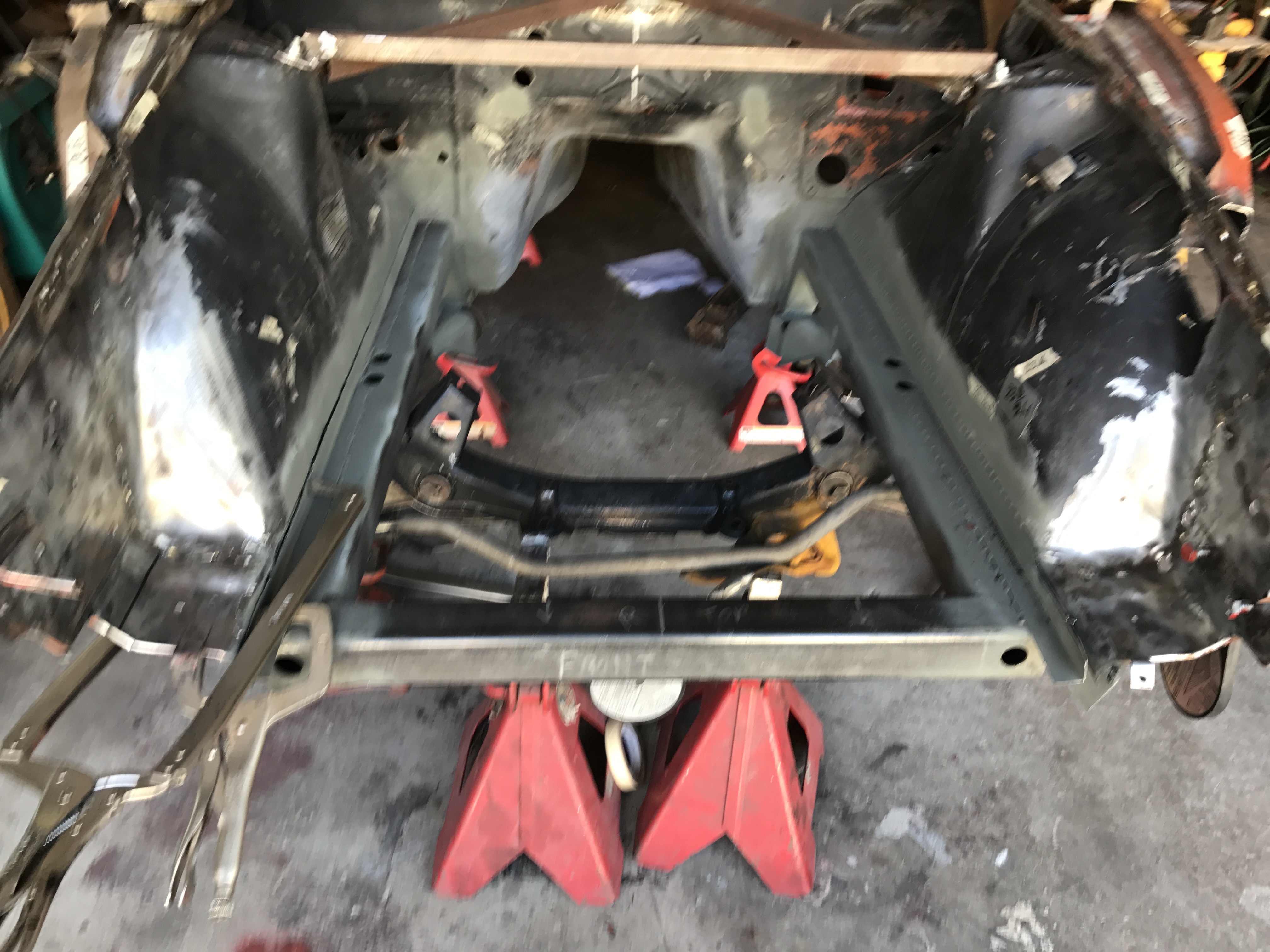
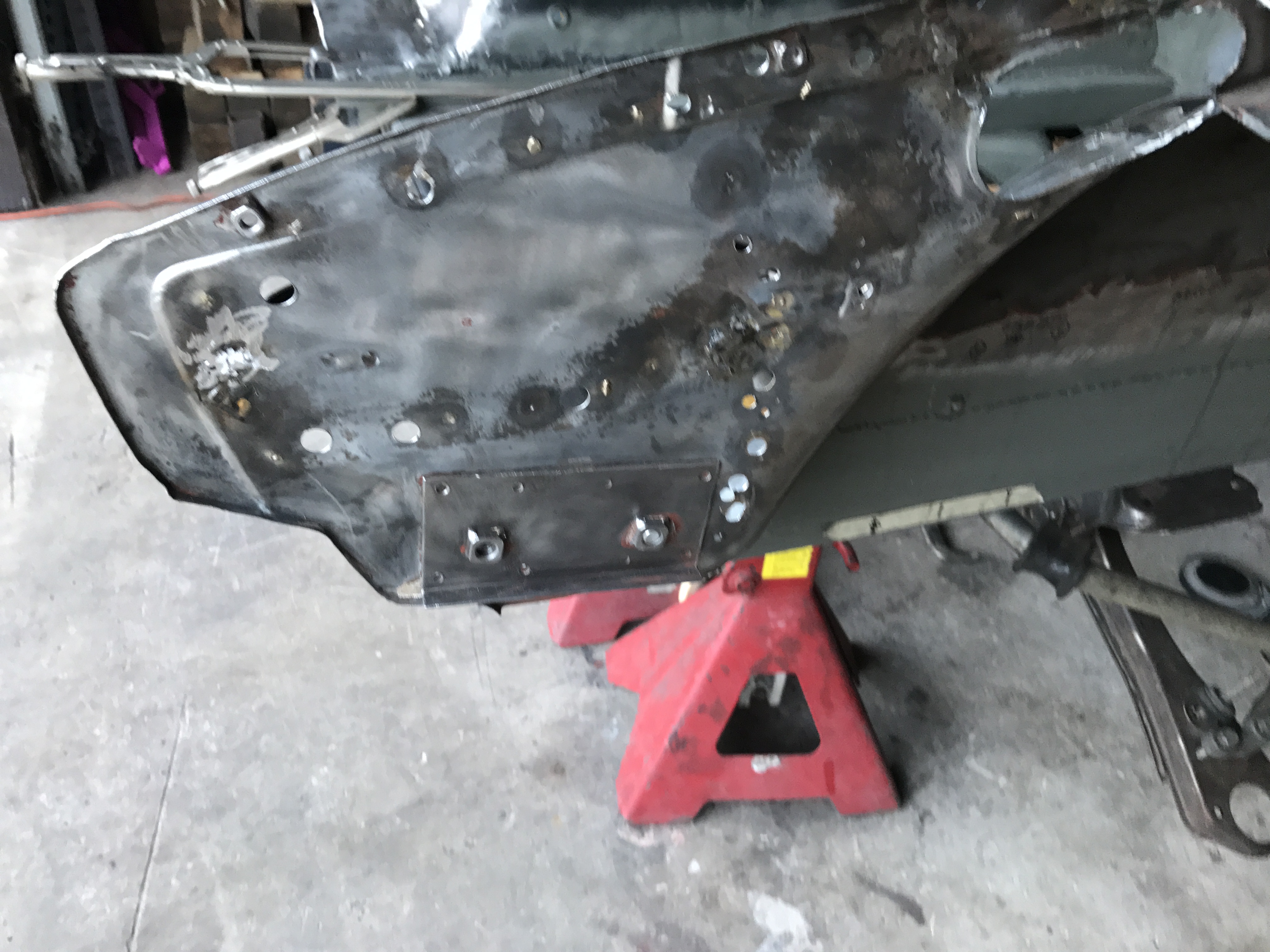
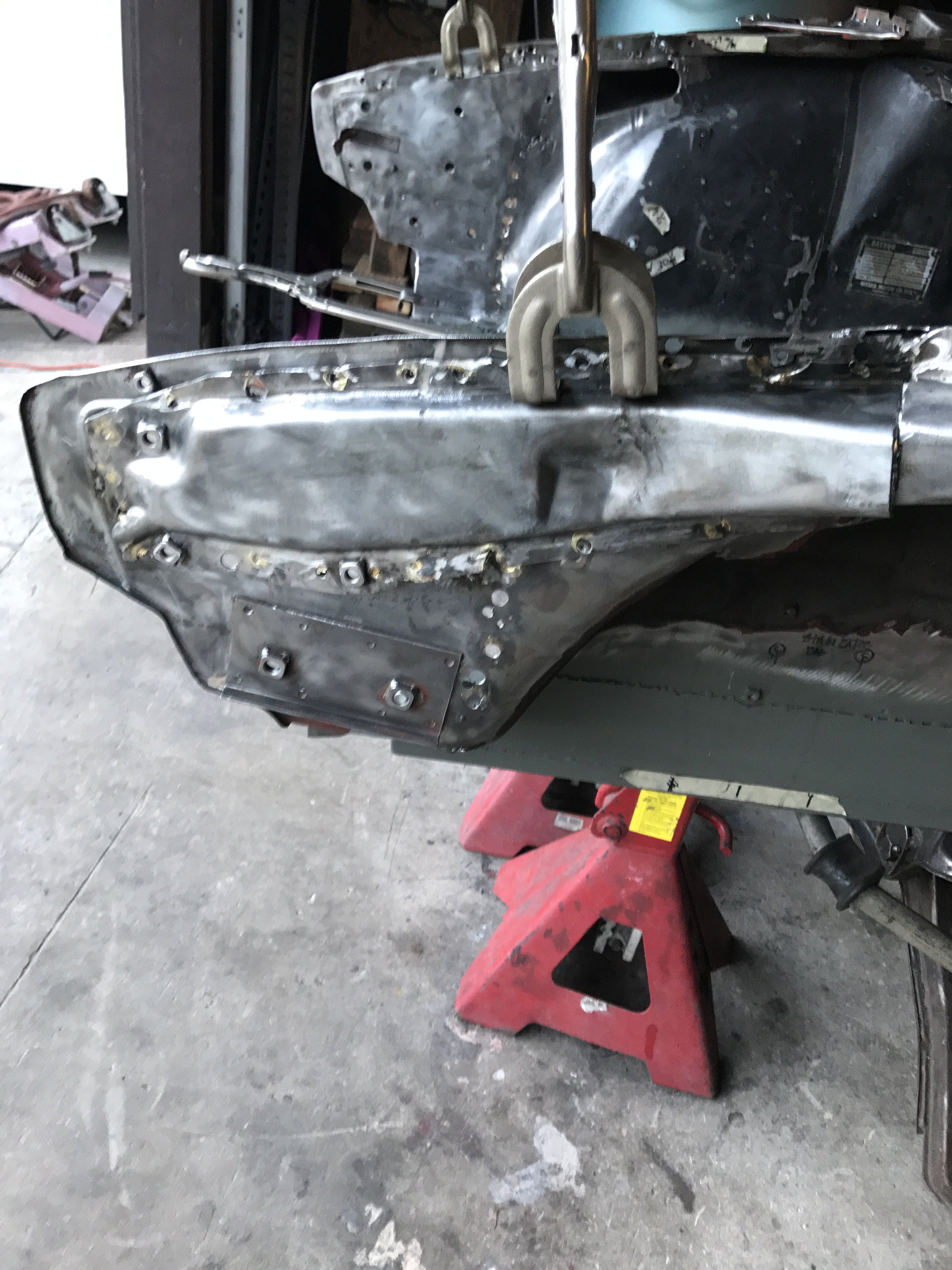
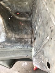
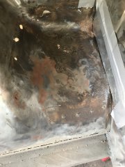
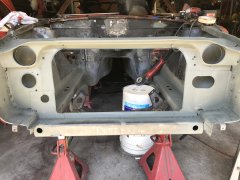
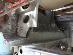
First picture is the completed radiator core support. It is welded to both sides of the front fenders and to the square tubing frame. Picture 2 show the rear of the support. I drill holes in the inside of the front tubing to lighten it and for looks. The third picture shows the front area where the bumpers and hood hinge are located. Spacing of core support and hood hinges are critical to prevent interference of moving parts. Check clearance before welding support in. Next step was to strip the engine compartment and weld up any small unnecessary holes. But I discovered the area under the battery holder was corroded. So the holder was cut out. Photo 4 shows the corrosion. Pic #5 is corroded area is to be cut out. The last pic is the top view of the patch to be installed .
-
Heavy Duty frame rails and connectors
toolman replied to toolman's topic in Gen III & IV Chevy V8Z Tech Board
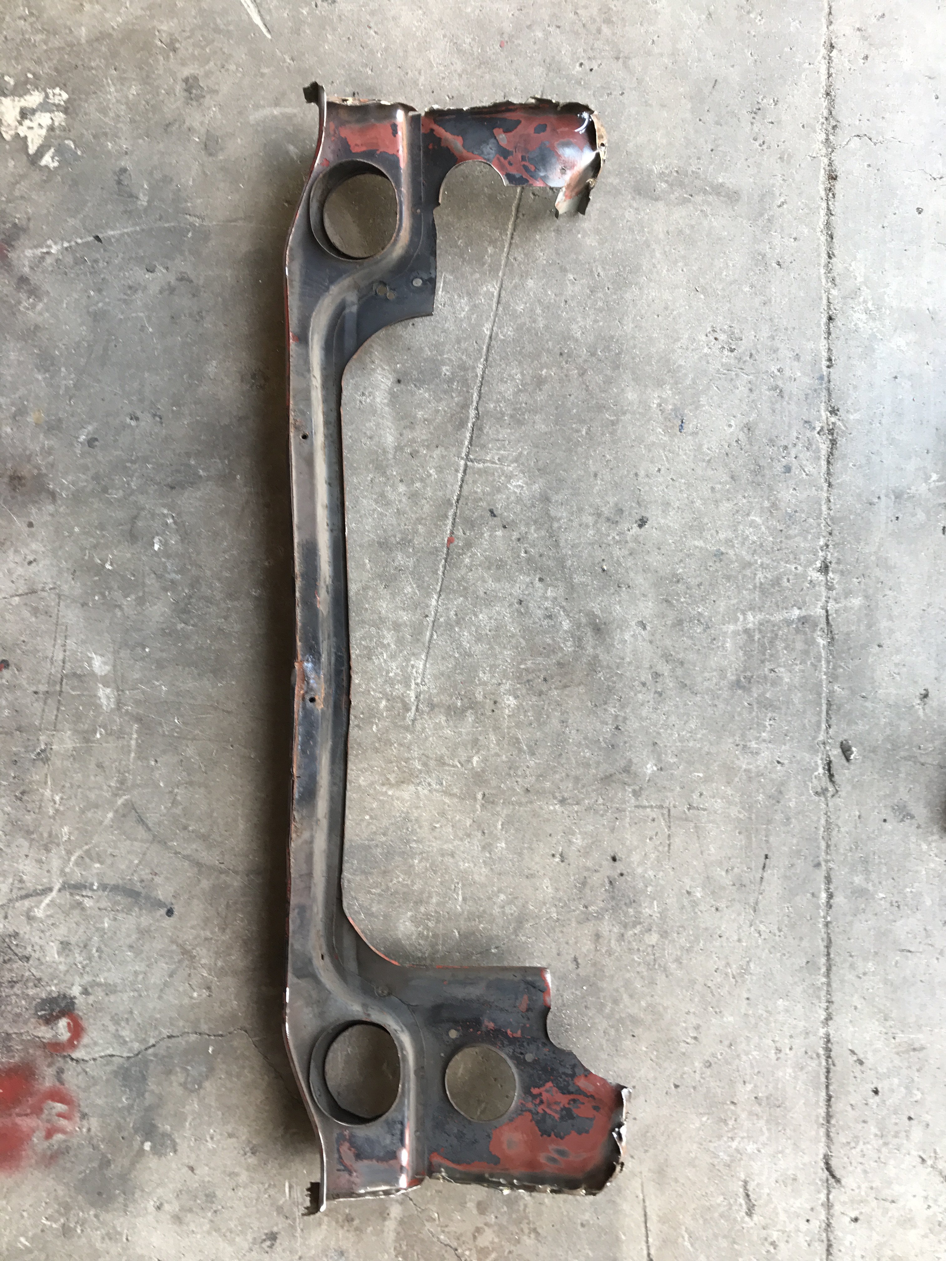
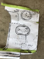
Yes, the ducts in the radiator support are constructed with sheet metal. I followed the basic pattern of the factory panel. Those extra holes will probably used for AC condenser hoses. Larger holes may be necessary if I go to a PRO-CHARGER supercharger for the intercooler. In that case. new grill would be constructed too. -
Heavy Duty frame rails and connectors
toolman replied to toolman's topic in Gen III & IV Chevy V8Z Tech Board
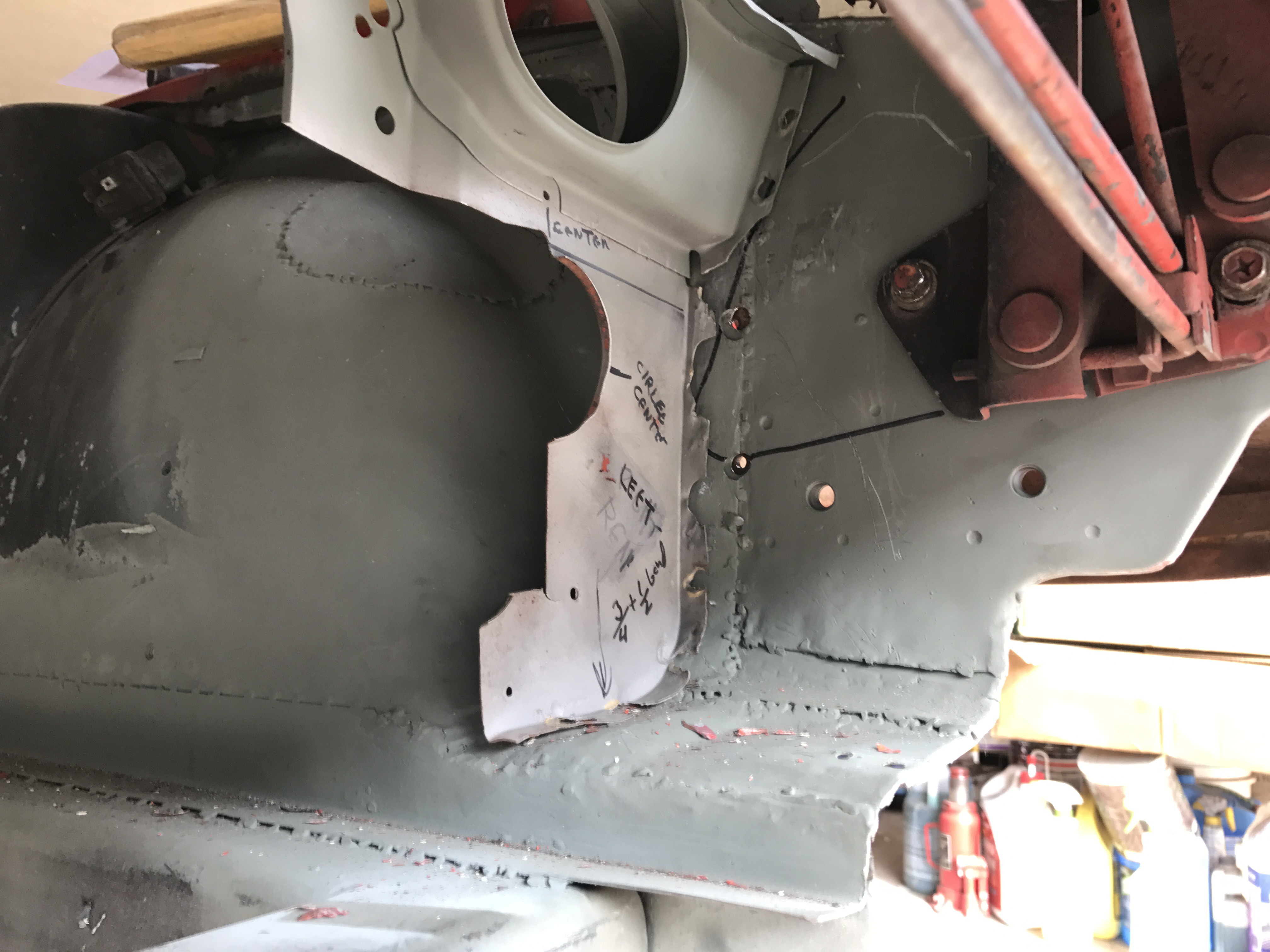
First pic is the "before" of left radiator support. Second is the paper template for replacement section. Third one shows the replacement mocked in. Fourth is of the"before" pics of the right radiator support. Fifth shows the replacement section mocked in. The last photo is the overall view of the radiator support awaiting welding.
-
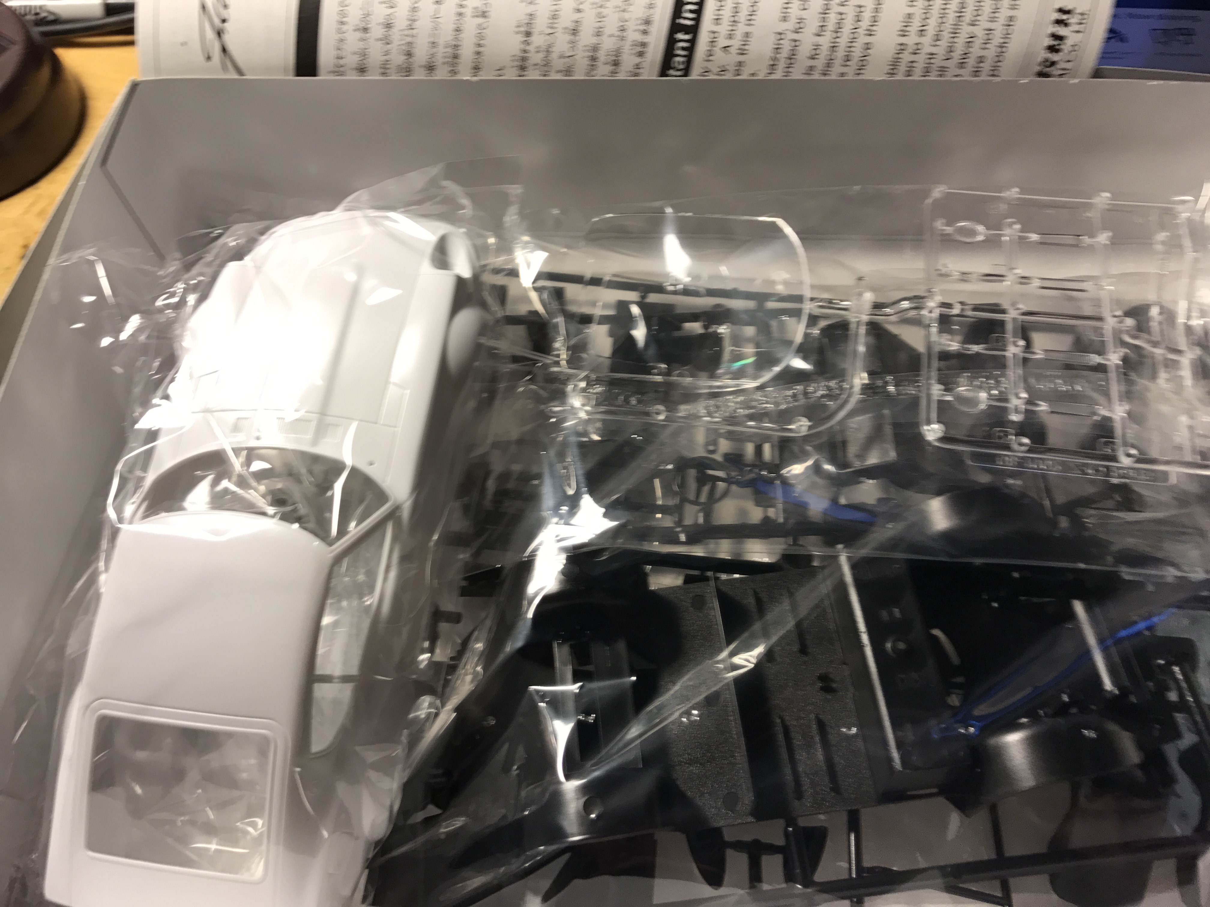
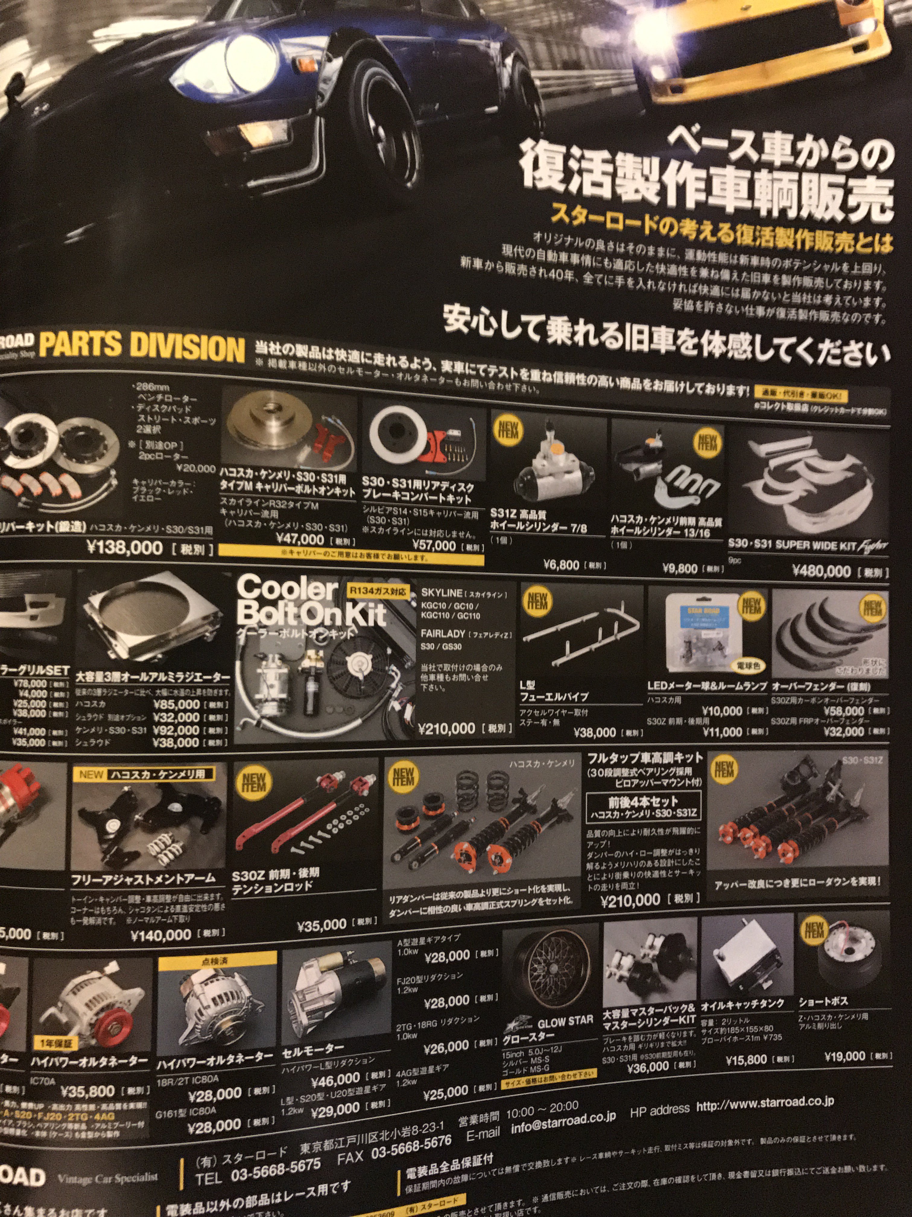
While in Tokyo, I found this plastic 240Z model car at a toy store. Fairlady Z is what the Japanese called the 240Z. They came with a twin overhead cam engine. Also some had GT front end nose too. This model car was about $20.
-
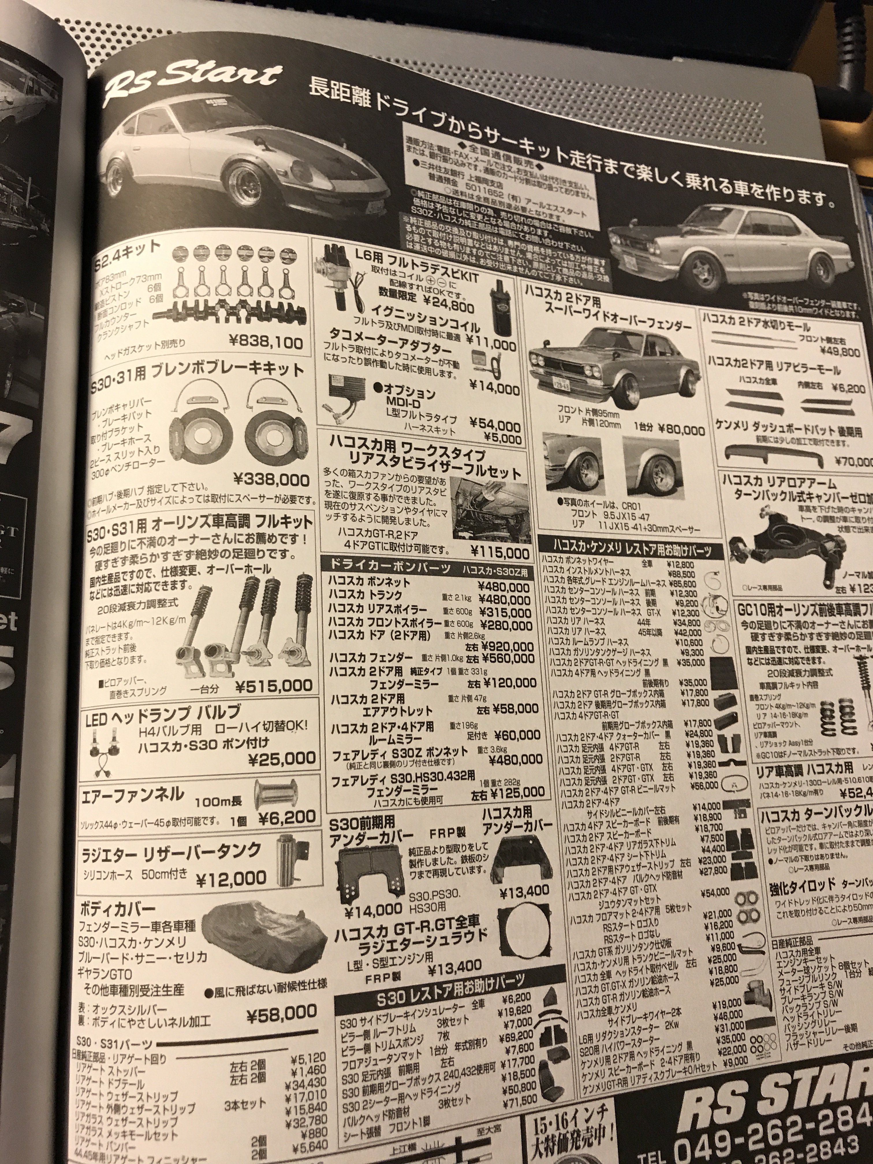
Sorry for the blurred pictures, I didn't realize it until after posting them. Added additional pictures. typical car magazine ads in Japan
-
Heavy Duty frame rails and connectors
toolman replied to toolman's topic in Gen III & IV Chevy V8Z Tech Board
Thanks for the support. Sometimes these projects become bigger than anyone can predict. While the ribs were off, I double checked the front area in front the both struts and found the left side was 1" higher than the right. I called my friend who has a 70 240Z to take measurements off his car. I confirmed that the right side was correct and left side was high by 1". Since I didn't have a frame machine handy, I decided to section the left side and raise it 1". See photo 1 welded a 2" sheetmetal strip to reinforce the joined area on the inside, This area will be covered by the new radiator support. Pic 2 show the rib rewelded in and new section above the rib to provide a smooth transition between altered section and old area. Pic 3 show additional sheetmetal strip welded in to reinforce the outer section. This was necessary as this panel has handle the hood hinge and bumper brackets.
-
Heavy Duty frame rails and connectors
toolman replied to toolman's topic in Gen III & IV Chevy V8Z Tech Board
Wheeler, Your frame rails look great. Are you going to race the car? I started to do detail work on the engine compartment and decided to work on the radiator support instead. While measuring the areas in front of the radiator-area where the bumper and hood hinge attach to) needed straightening. First picture shows the old radiator support. Second pic is of both areas stripped of paint and cleaned. The third photo has the right side with the reinforcement rib removed to fix under it. Fourth pic had the rib replaced and ready to rewelded on. The fifth photo is the left side with the rib removed and damaged area repaired. Sixth pic show the rib replaced awaiting to be welded back. The vehicle was in an accident before I bought it and the area( crush area) was not repaired as that would require rib removal. Next to be done will the construction of the replacement radiator support.
-
Heavy Duty frame rails and connectors
toolman replied to toolman's topic in Gen III & IV Chevy V8Z Tech Board
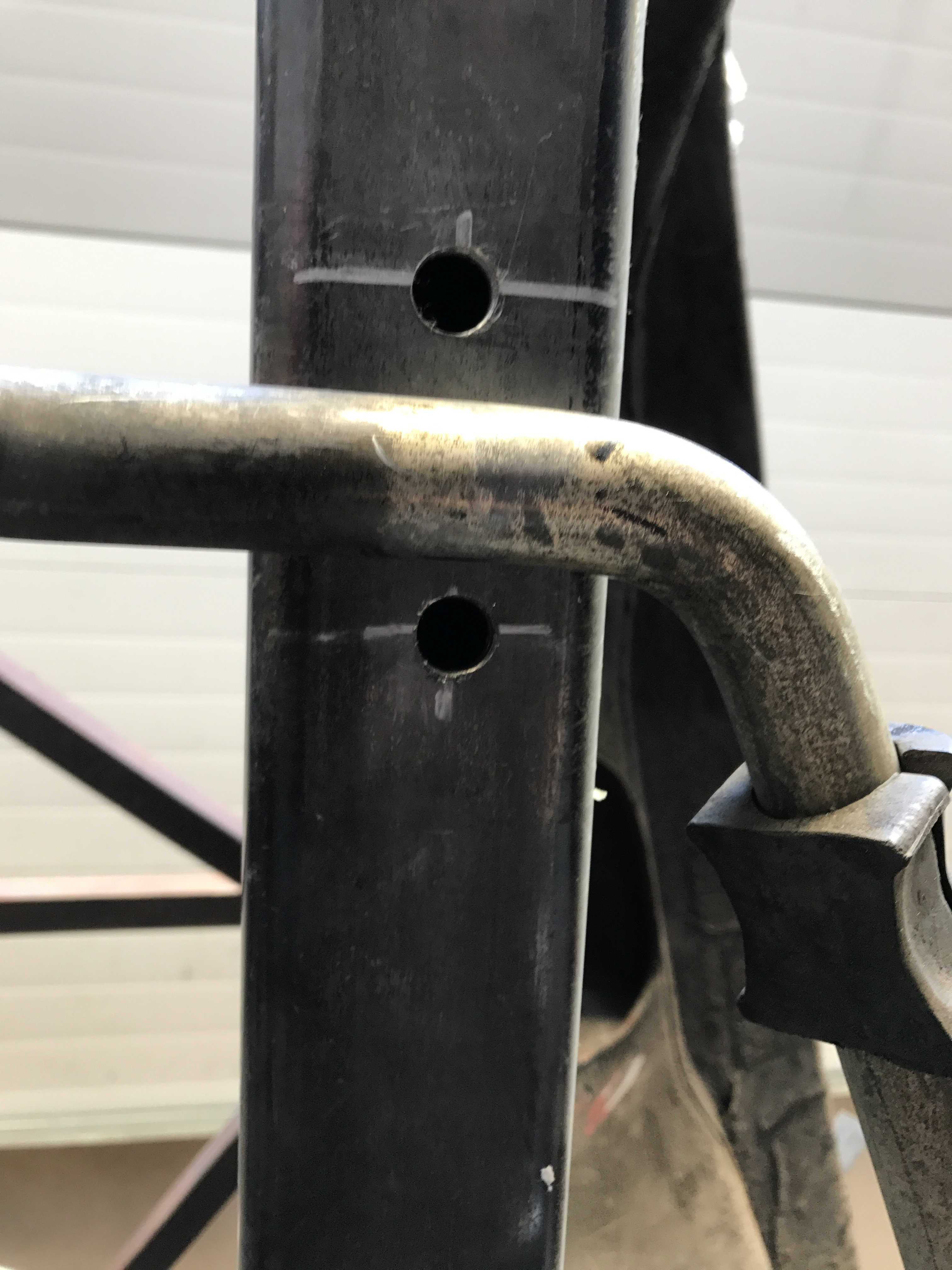
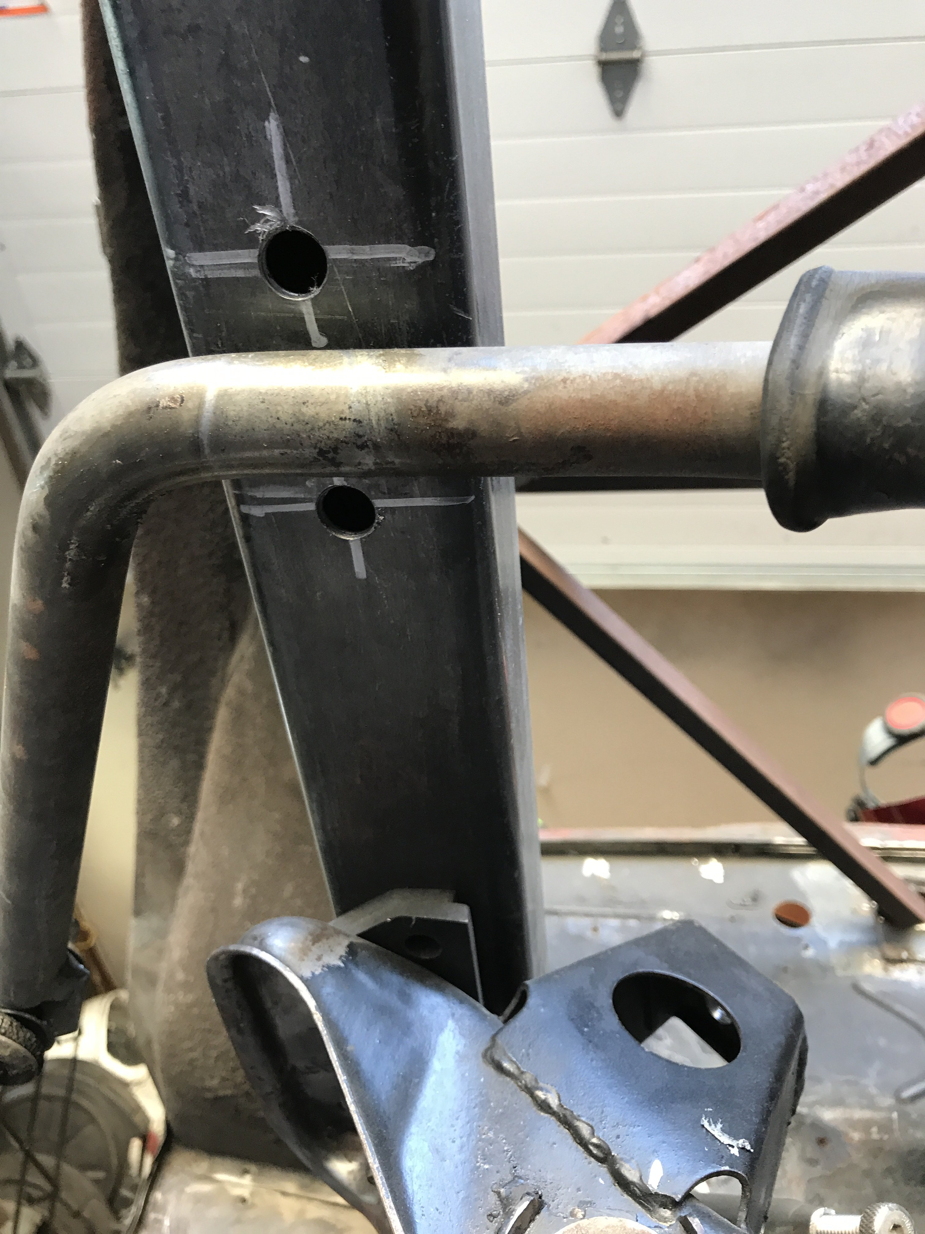
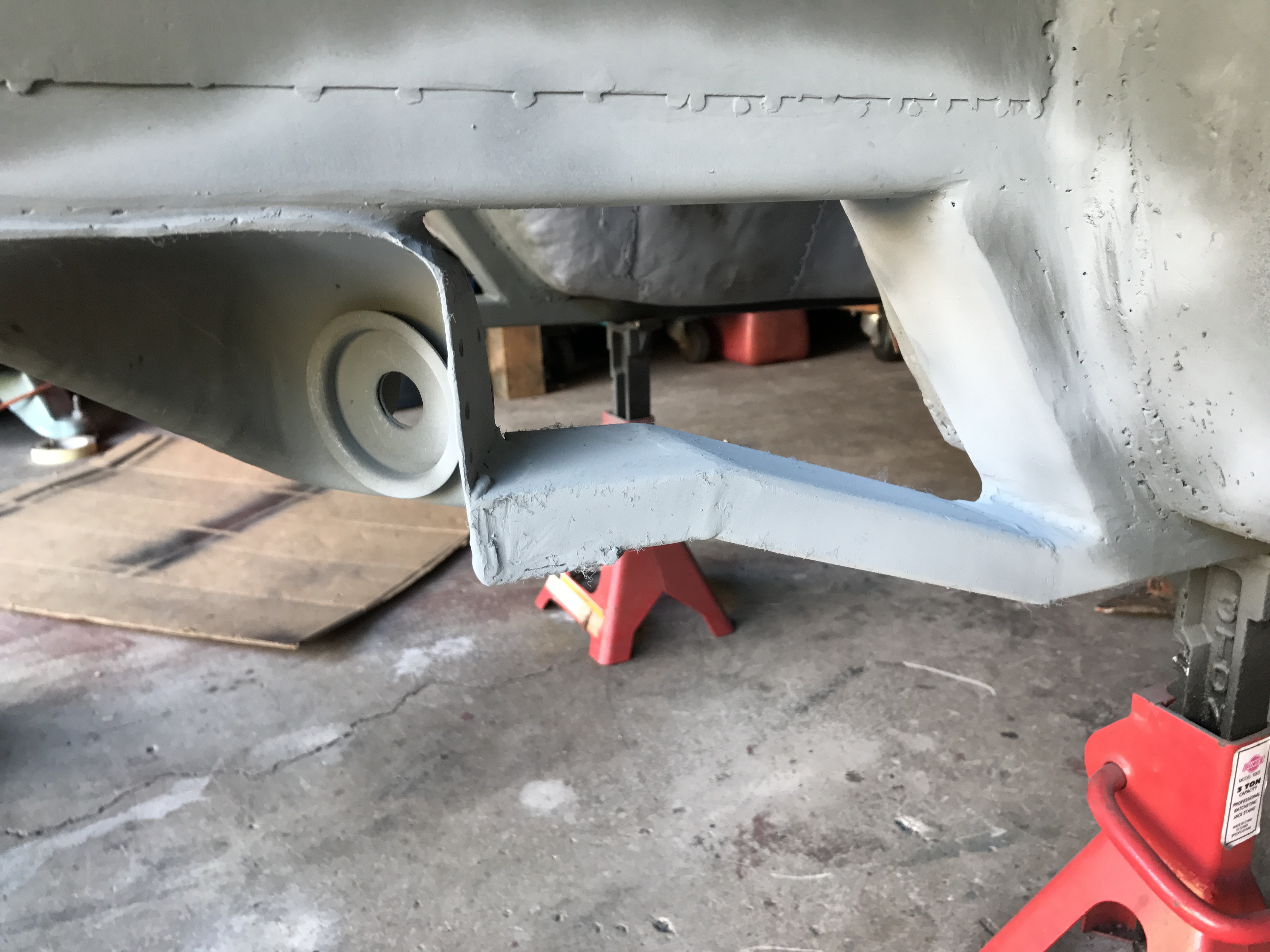
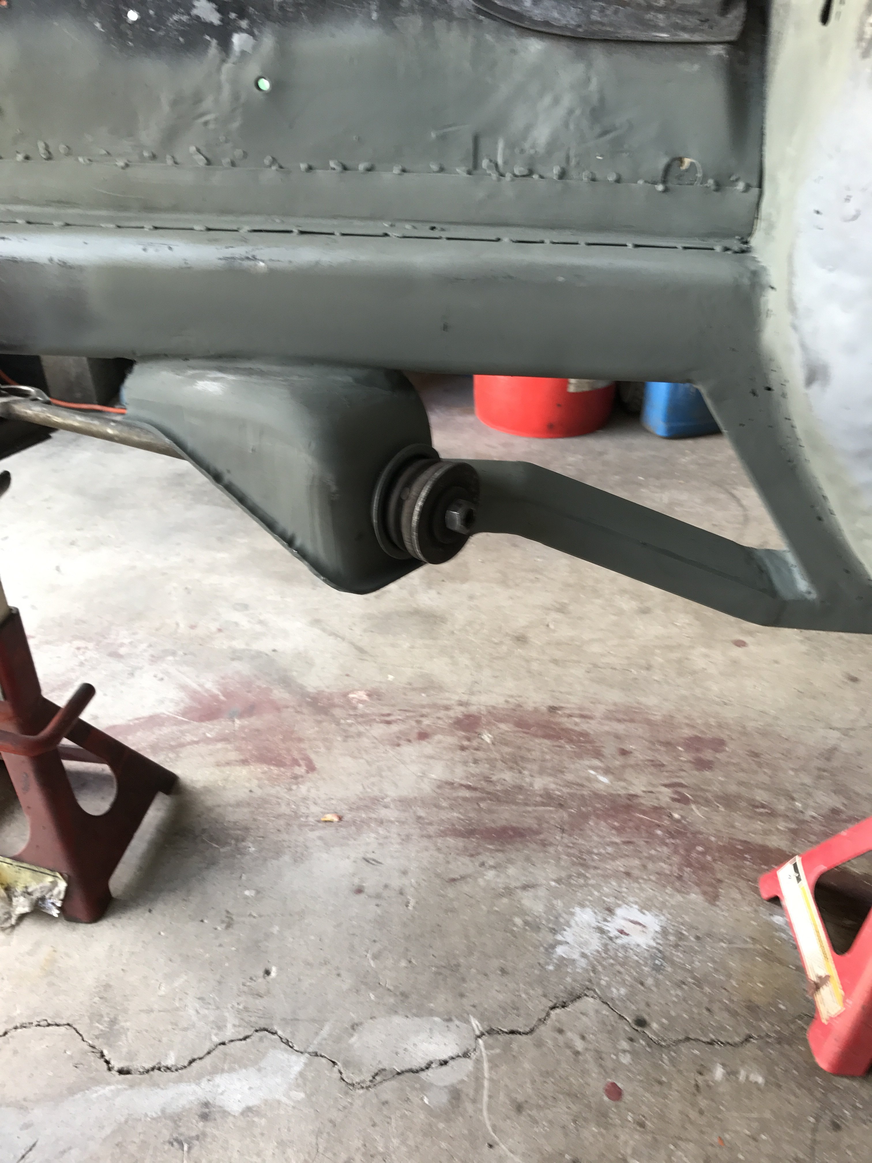
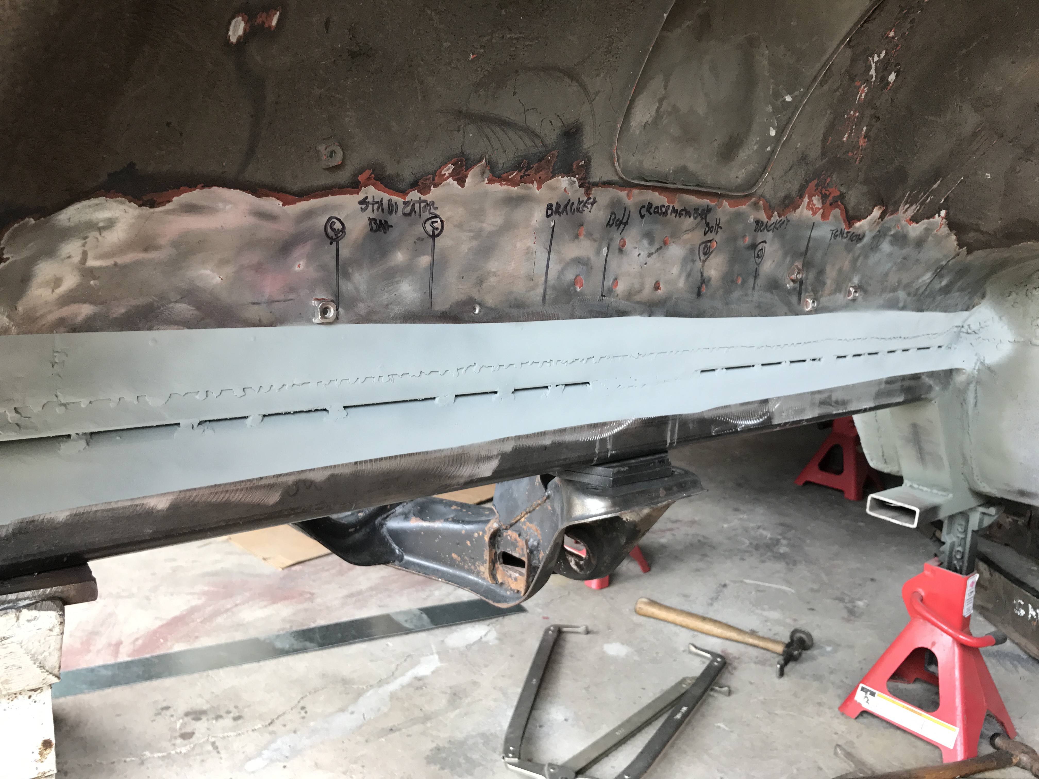
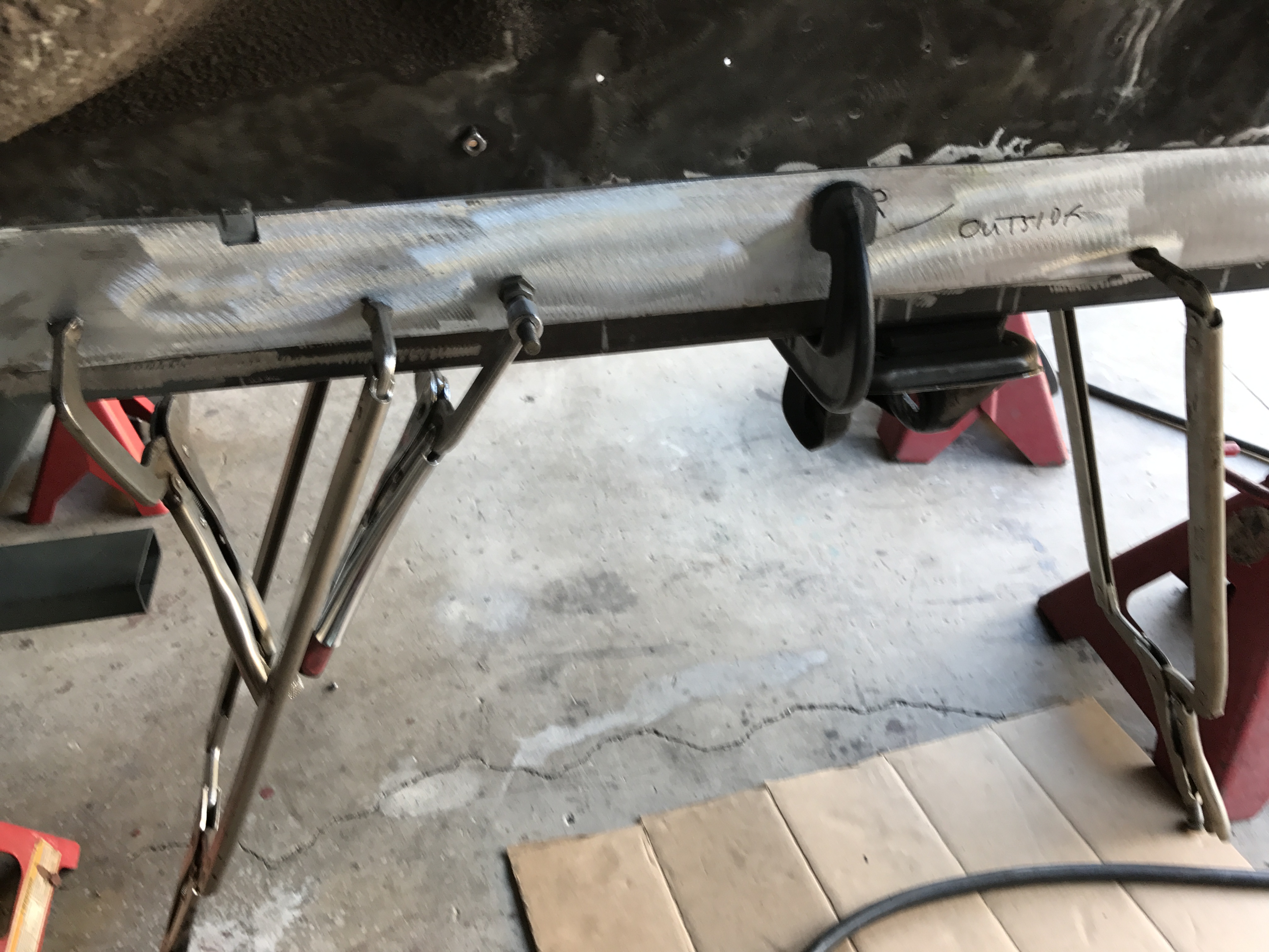
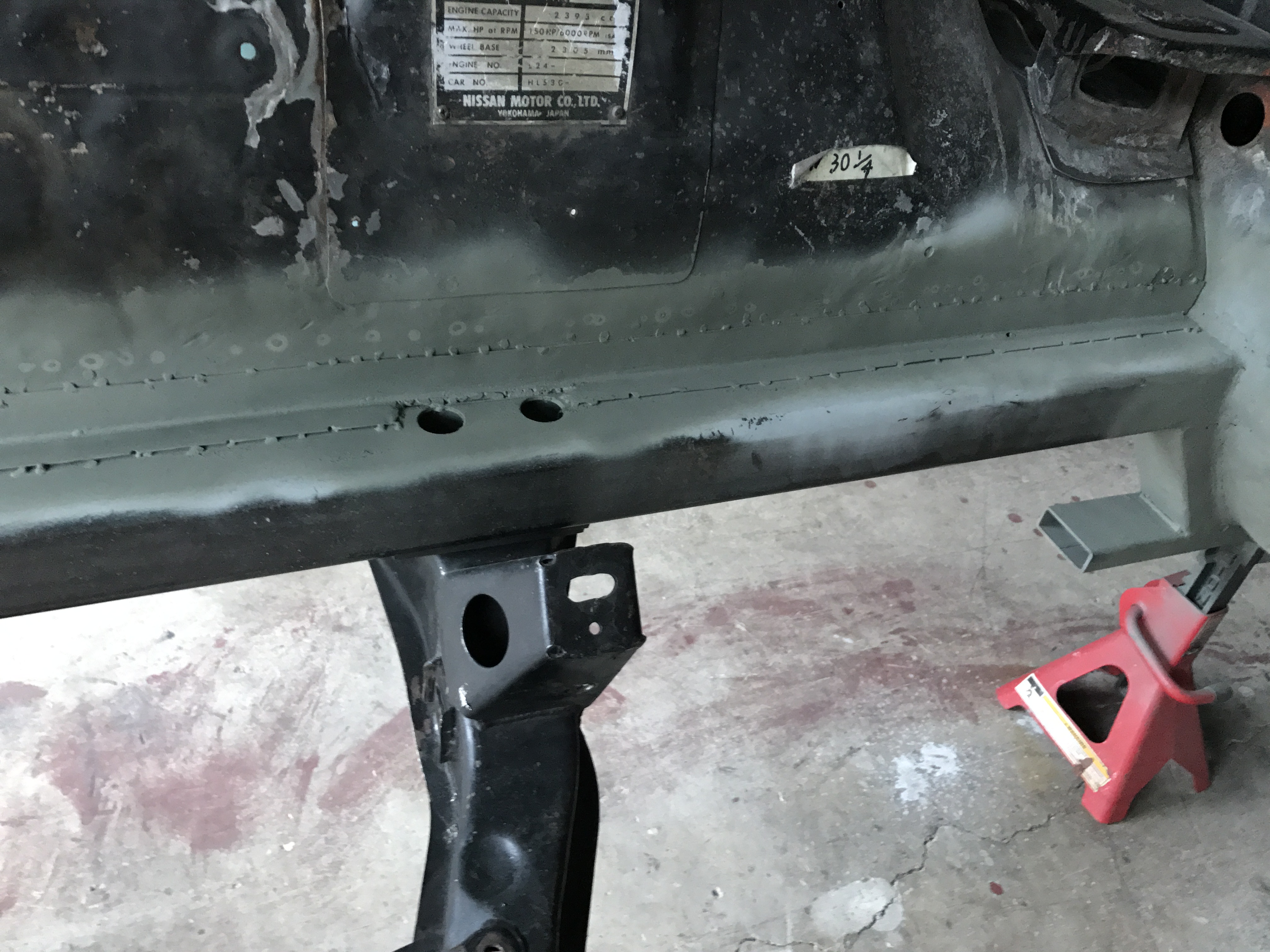
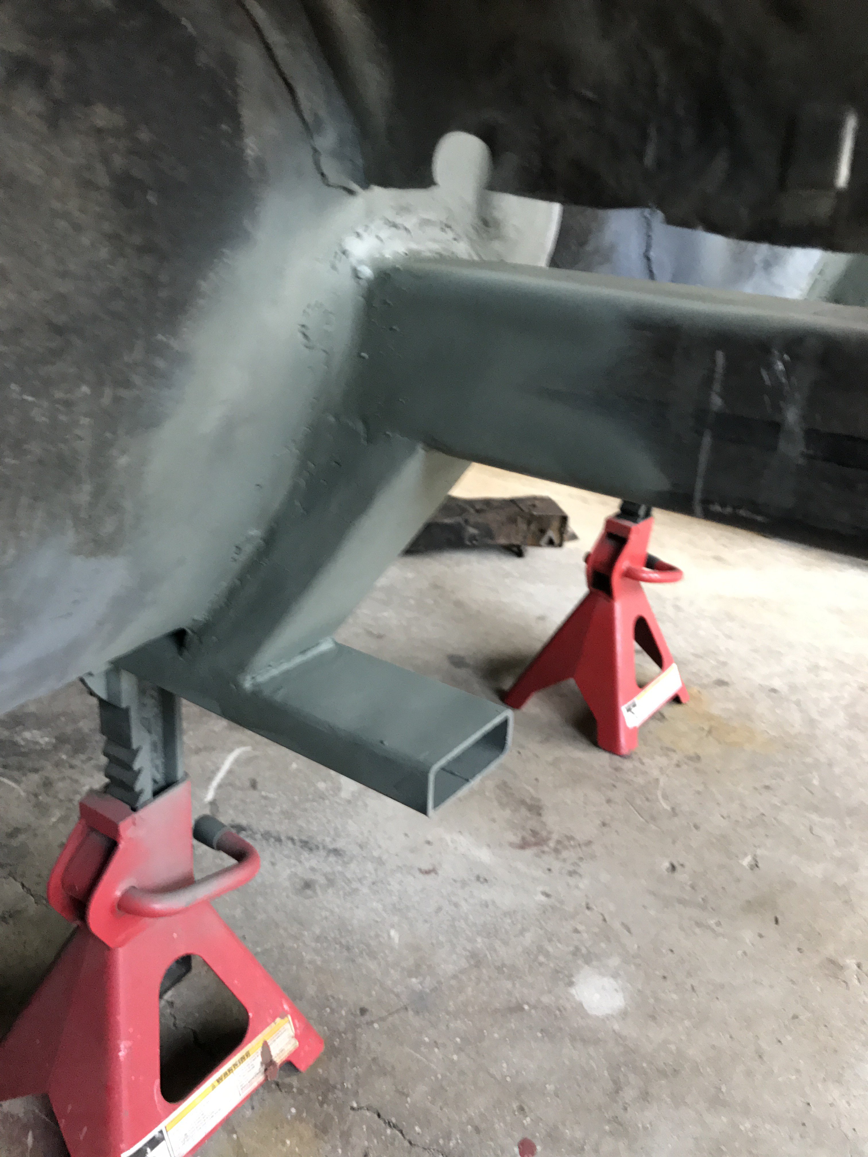
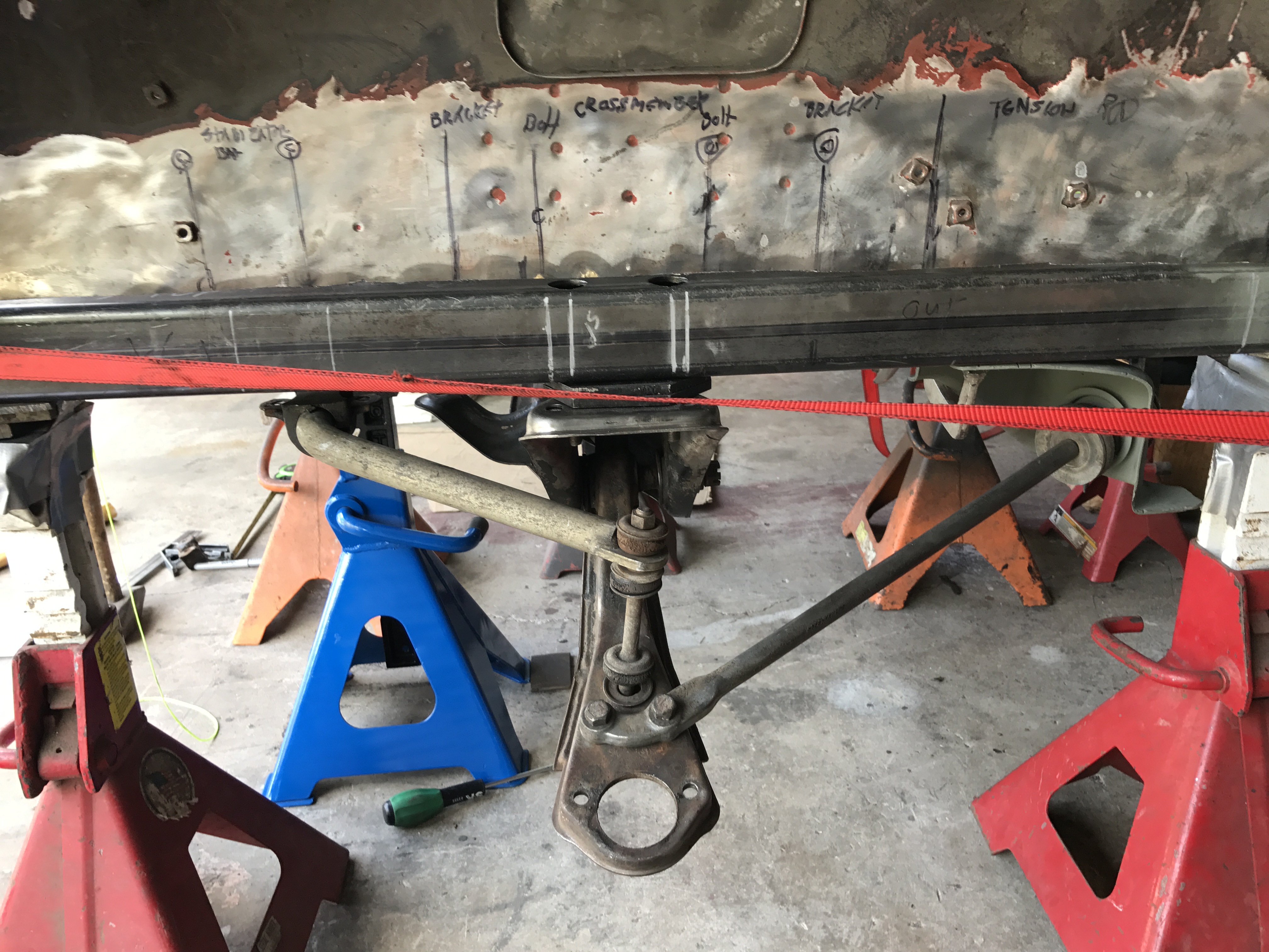
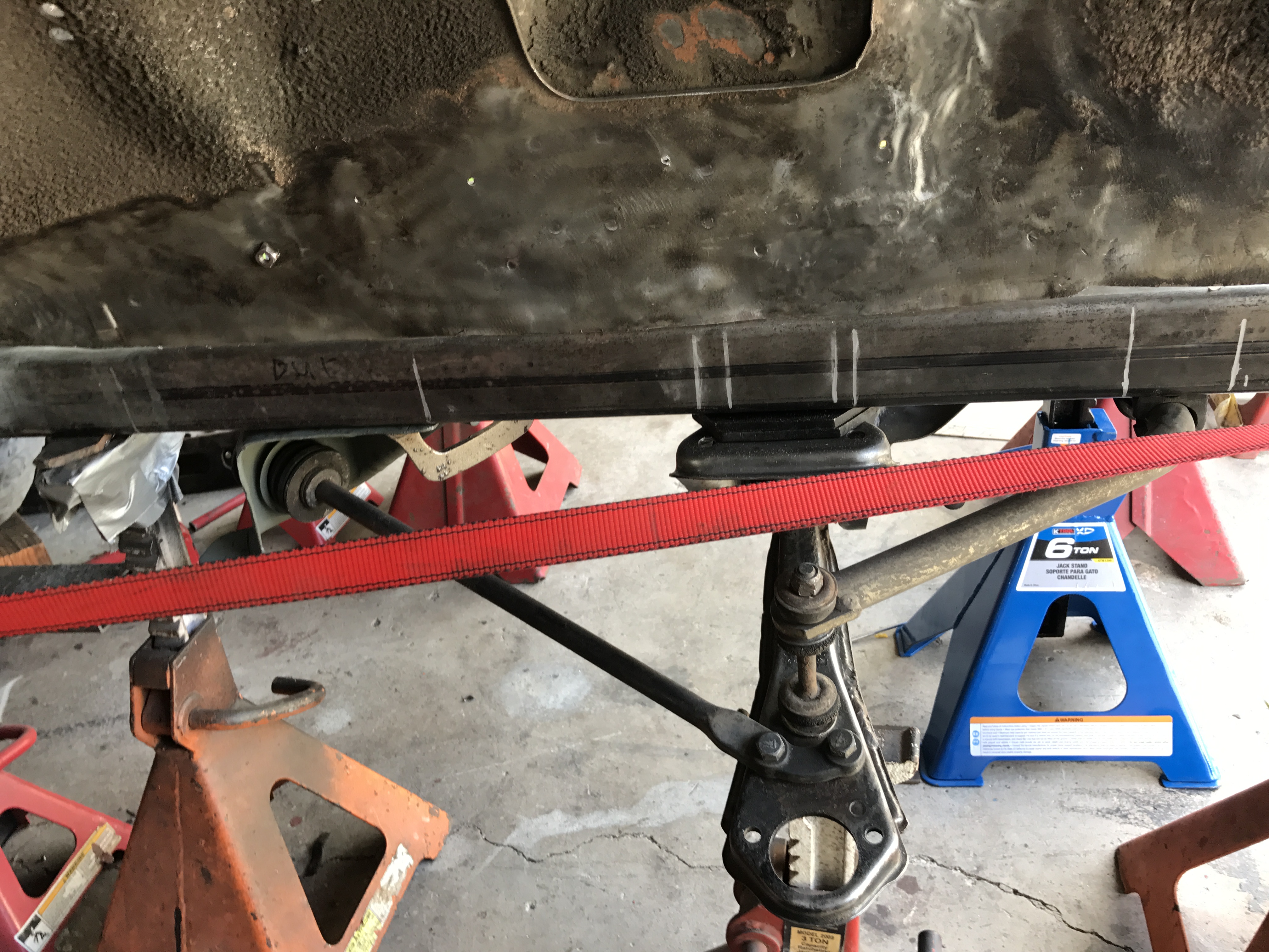
First photo is the left side stabilizer bar mounting holes( a plate with corresponding nuts welded to it will be installed in the frame rail later) Second pic is the right side stabilizer mounting holes. Third picture shoes mocking up in preparation for welding of the tension rod bracket. Fourth pic is the completed left side bracket. It is constructed of 3" x 1"x 1/8" steel tubing (same as frame connectors) The angle section is set at 20 degrees. Fifth photo is the inside view of the bracket. Sixth photo is the outer view of the right side tension rod bracket. Seventh pic is the inside view of the tension rod bracket. Both left and right tension rod brackets will have 20 gauge plates welded to inside and outside of them. This will replicate the factory appearance.
-
Heavy Duty frame rails and connectors
toolman replied to toolman's topic in Gen III & IV Chevy V8Z Tech Board
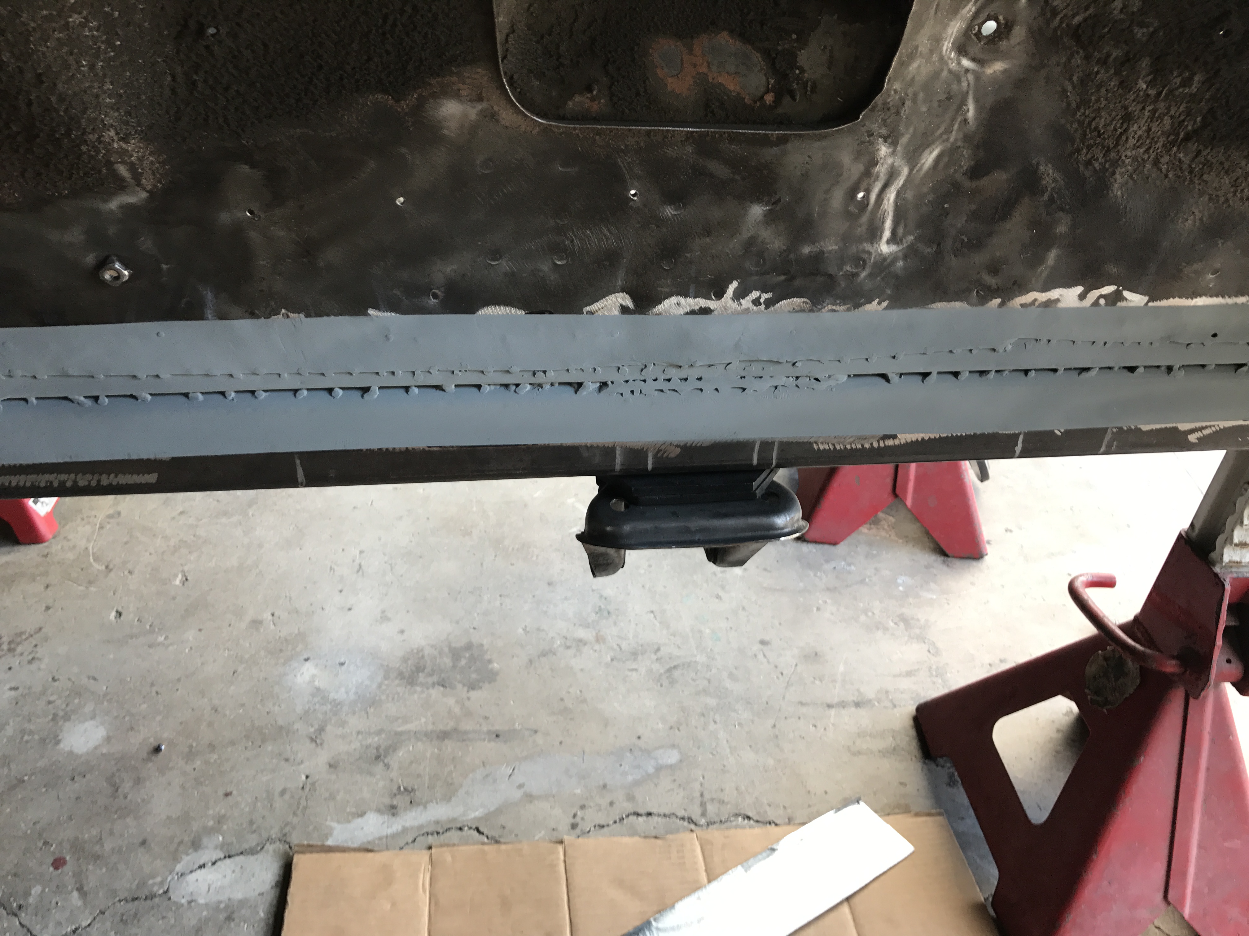
First photo is the "before picture" of the left side of frame rail. Notice 1" gap. Second pic is 3/4" X 2" right angle 20 gauge sheetmetal welded to subframe and existing sheetmetal Third picture is outside view of right angle connecting pice welded to subframe and wheel housing. Fourth pic is an additional 20 gauge 3" wide and about 48" long welded to the subframe and existing sheetmetal. This will provide additional strength and looks better. Fifth photo is right side frame rail with connecting right angle support plate. Sixth pic shows welding the right side "cover plate'" to sheetmetal and subframe. Seventh photo is engine compartment view of the subframe and connecting piece. All the mig welds will covered with urethane seam sealer after media blasting. Next step is construct tension rod support brackets for both sides.
-
Heavy Duty frame rails and connectors
toolman replied to toolman's topic in Gen III & IV Chevy V8Z Tech Board
First photo is the left side frame rail with the frame connector welded to the firewall. Second picture is the passenger side frame and frame connector welded to the firewall. I was glad that put a 16 gauge reinforcement plate under the frame rail. Otherwise, welding 1/8" frame to 23 gauge firewall would be extremely difficult.
-
Heavy Duty frame rails and connectors
toolman replied to toolman's topic in Gen III & IV Chevy V8Z Tech Board
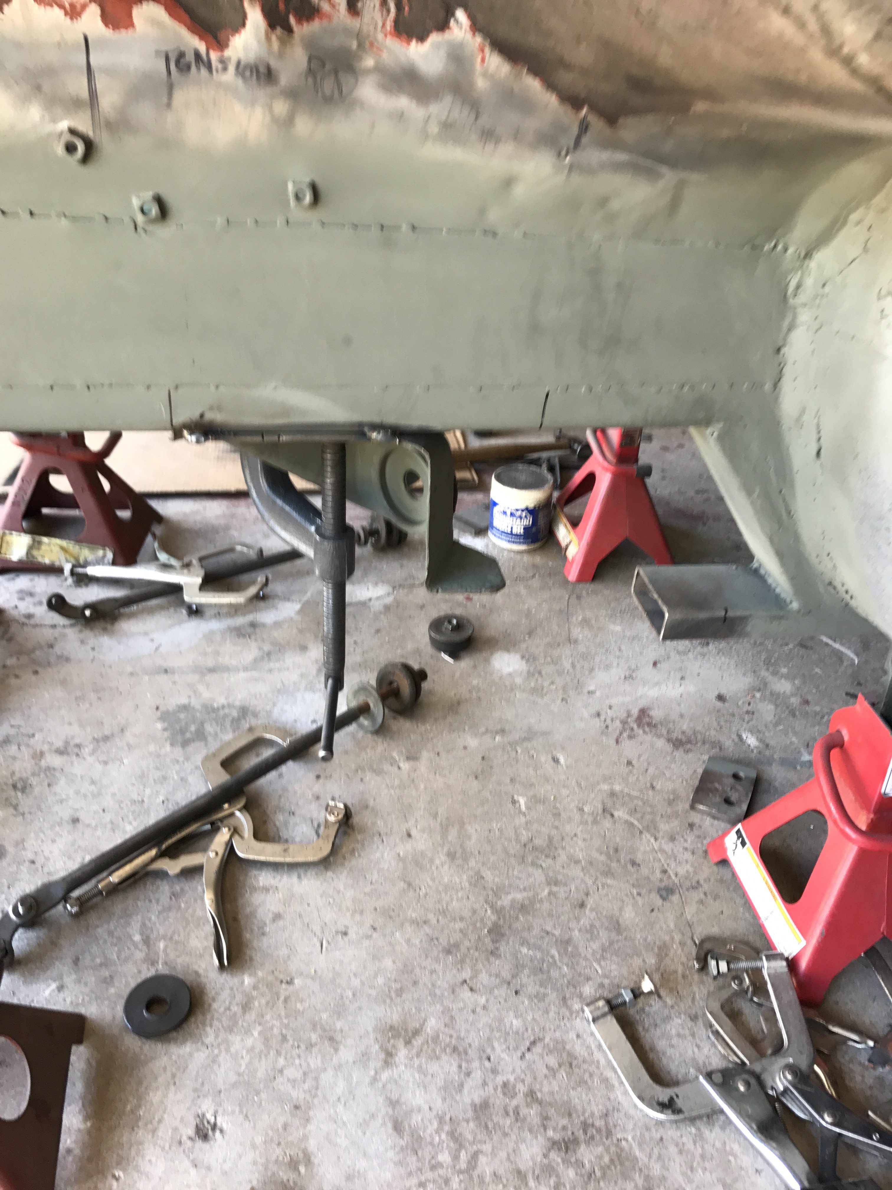
The first picture show a better view of the plumb line. The second photo show the left suspension mockup. The third picture is of the right side suspension mockup. The fourth photo is a closeup of the left side crossmember. Note the two 1" assess holes in the top of the frame rail. The holes will capped off later to prevent water and debris from entering.