Bob_D
-
Posts
34 -
Joined
-
Last visited
Content Type
Profiles
Forums
Blogs
Events
Gallery
Downloads
Store
Everything posted by Bob_D
-
I also took my clock apart ('73 240Z), cleaned and oiled it (very carefully) and it worked great for about a year keeping perfect time, but now it's losing about 10 minutes a week, so I think it's due for another cleaning. That clock had not worked at all for close to 15 years when I pulled it, cleaned and lubed it, so it's possible to revive these things, assuming the electric motor still runs.
-
Hi Joe, so after I cleaned out the crud in that hole I did indeed discover it to be a blank. No threads at all, but it has the appearance that it might be able to be drilled out and threaded, which perhaps they did for a different market or application, since that tail casting could have ended up in a different car or truck when mated to a different bellhousing. So yeah, kind of weird that the 5 speed ONLY has a reverse sensor, where as my old 4-speed had both the reverse and neutral sensors. In the end I think I just left the neutral wires in the chassis harness unconnected, but the car will still start in neutral. I'd have to crawl under there to be sure... maybe I connected those neutral wires together? The memory is fuzzy now. FWIW having the 5 speed is GREAT, especially when everyone around you on the freeway wants to be doing 80MPH. I can keep up with traffic and stay below 3000 RPM (stock rear gears).
-
Thanks for the quick reply NewZed. So it looks like my original flywheel, plus the new '73 clutch, Pressure Plate, Throwout Bearing AND '73 sleeve/collar mated to the 5-speed should work fine. Motorsport Auto only has 1 slave cylinder for '73-'83 Z & ZX (non turbo) cars, so that answers that question (which is great since I replaced both the master and slave cylinders not too long ago). Thanks for the heads up regarding the use of the original 4 speed shifter in the 5 speed, that tidbit wasn't mentioned in any of the discussions I have (so far) come across. Now, I "just" have to finish putting my engine back together in order to find out just how well the 5-speed works out for me.
-
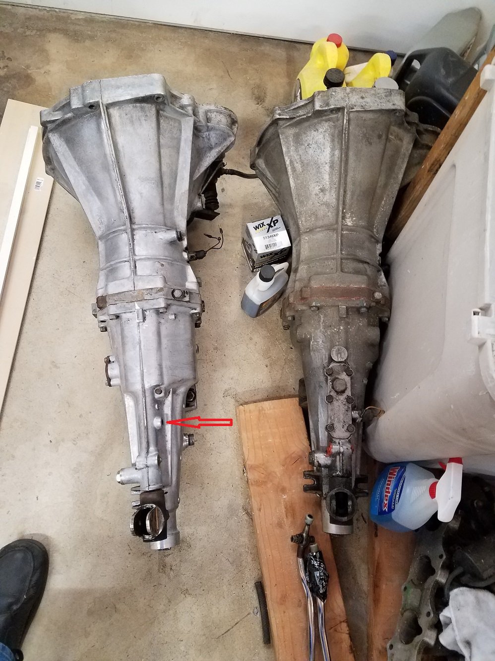
I recently acquired a late model FS5W71B 5-speed that supposedly came out of a 280ZX. It definitely has the right bellhousing bolt pattern, the single ear exhaust hanger, the reverse check plate, and the tall ears for the shifter. I've put it in 5th and counted input shaft to output shaft ratios, and confirmed it's the .745:1 5th gear. Based on the research I've done on this site and others it sounds like it should bolt in just fine, but I need to make sure I use the pressure plate and throw-out bearing out of either one or the other and not "mix and match". I have a completely new clutch/PP/TOB (Exedy) that I had bought for my 4 speed, and am guessing that it should be OK in the 5 speed? Can anyone confirm this? Also, the breather has broken off flush with the case. Any advice on removing the stub? The 5-speed came with a slave cylinder, should I use that one or my 4-speed's, or is there no difference? Looking at this web link http://www.atlanticz.ca/zclub/techtips/shifterbushing/index.html I do have the weird oblong shifter (bottom picture, right side) from the 5 speed. Does anyone have any idea what that internal spring is supposed to do in relation to the bushings? Is it one of those push-down to engage reverse features? Finally, this transmission only has one electronic sensor installed, up near the front (Reverse switch I believe), and nothing else. There looks like maybe something should be in the rear, and possibly got broken off. I need to do more cleanup in that area to be sure. I downloaded a copy of the '83 FSM from Xenon and the MT chapter shows 4 sensors! (Reverse switch, Top Gear Switch, O.D. Gear Switch, and Neutral switch.) In all the pictures of these transmissions I have found on line I have never seen 4 switches installed on the side of these transmissions. Does anyone know what the deal is on what reality appears to be VS what the FSM is calling out? In my picture the 5-speed is on the left, the 4-speed is on the right, The shifter with all the tape around it is the oblong one out of the 5-speed. The boss that is up from the tailshaft on the right of the center casting part line (red arrow pointing to it) is full of crud and I suspect where the neutral switch should be installed. Is there ANYTHING that anyone can advise me on in regards to making this swap successful? Pitfalls? "Gotchyas"? "As long as you are doing this you may want to..."? Thanks!

-
Lorenzo, sorry for the late post reply, hopefully you have fixed the issue by now, but just in case you are still hunting for the trouble, I had a charging issue on my '73 very much as you are describing, and it turned out to be a corroded wire in my VR connector. It looked just fine, and I had plugged and unplugged that connector maybe 1/2 dozen times, but it wasn't until I really got in to every connector, cleaning out all the debris and crap that collects in those things, that I discovered the yellow wire was not actually connected! I purchased a new connector from http://vintageconnections.com/ and rebuilt that connection. Everything works great now. Good Luck!
-
Pertronix Ignitor II / Flamethrower II
Bob_D replied to P-Funk's topic in S30 Series - 240z, 260z, 280z
Hi P-Funk, I put the Pertronix Ignitor II and Flamethrower II in my '73. I kept the ballast resister, as the instructions indicated this was the way to go with an otherwise stock engine. My tach works fine, but where I really noticed an improvement is when I ditched the old 40 Amp alternator and upgraded to the internally regulated 60 Amp set-up, as detailed on this site in other posts. Open up your plug gap to the max suggested gap (.038 if my memory serves correctly) once you have the higher output Alt. I noticed that it's easier to start cold and seems to rev up a bit more "snappier". But as NewZed points out, you do have options for electronic ignition, but not all are compatible with a stock '71 tachometer. -
I realize this is a long-overdue answer, but in order to help out the community and anyone else who may be curious, here is your answer. On my stock 1973 240Z exhaust system, the resonator has a round body with "bullet" shaped ends. From where the end meets the pipe to the other end where it meets the pipe, it's 12" long. The body is 3-9/16" in diameter. The muffler is constructed in a manner not unlike a soup can, resulting in raised edges at both ends. From the end of those raised edges to the other end it is 14" long. The muffler body is 6-1/4" in diameter (the lip-edges are slightly bigger around). Where the exhaust pipe enters the muffler, the muffler has a little bit of pipe that protrudes to accept the exhaust pipe. The protrusion is 2-1/4" from the raised edge. The tail pipe that exits the muffler extends 8-13/16 beyond the lip of the raised edge. It flares out to a 2-1/4" outside diameter tip. The exhaust pipe itself is a puny 1-11/16" outside diameter.
-
Yeah, they have a point. On my 73 the electric pump would not work with the alternator upgrade plug, using the stock Datsun "ADD-ON" harness. And by that I mean the short "extension" pigtail at the voltage regulator that adds a yellow wire back to the interior along with an extra wire from the starter solenoid also going into the interior. These two wires, along with additional wires from under the dash, feed into 2 relays in the passenger foot-well area. I ended up removing all that added-on wiring and 2 relays, and connected the connectors behind the radio but spliced in a fuel inertia cut-off switch for safety sake. Pump comes on when the key is in the run position (still using the stock wiring back at the pump). Seems like a bit of a pain, but the alternator upgrade is well worth it, and removing all the excess harness and relays helps to clean things up in the engine bay and in the passenger area. At some point in the future I plan on adding a hidden anti-theft switch and a relay to the system so the pump won't activate unless a hidden switch is turned on, but for now this works.
-
occasional sputter and stall
Bob_D replied to rickyellow zee's topic in S30 Series - 240z, 260z, 280z
Hi Rick, I know this is going to be an apples and oranges thing here, but I one had a '87 Ford Escort that had the ignition module mounted to the side of the distributor, and it would do the same thing. Allowing it to cool down, and it would work fine... for a while. Eventually I had to replace it. In fact I ended up replacing it about 3 times in the 300,000 miles I drove it, but the symptoms were always exactly as you describe. Good luck! -
Hi Dylan, I just fixed a similar problem on my 240. I have a '73 but with '71 SU dome-top style carbs. In my case there were several steps to fix this issue. 1st was my spark plug gap was way too large (even thought the plug color looked fine). I had put in a Pertonix electronic system and eliminated my points, and at the advice of a friend had opened up the gap on the plugs to .040. Turns out this wasn't the right thing to do for this particular engine. It really likes .035 (running NGK "stock" plugs). Second, my damper oil was low in both carbs. I removed my domes, cleaned everything, reassembled and used actual SU damper oil that I purchased from Black Dragon. It seemed a tad thicker than the 10W30 I had been using. Finally while I had the carbs synced fine at idle it turned out they weren't synced properly at 2500RPM, and required some adjustment of the balance screw (page EF 20 of the '72 factory service manual - if you don't have one you can find one here http://www.xenonzcar.com/s30/fsm.html HIGHLY RECOMMENDED). After doing these things my car came alive like it has never been in the 3 years I have had it. Idles smooth, accelerates strong, and the rich smell out of my tail pipe is gone. In addition it purrs on the freeway where as before it seemed to surge a bit. Finally my annoying 4500 RPM "wall" that the car seemed to hit has vanished, and it will rev all the way up to 6K no problem.(I don't have the guts to go any higher than that!) Hopefully this helps you out.
-
Awesome, Thanks 88dangerdan!
-
Thanks for the feedback, that helps to put my mind at ease in regards to getting one of these body kits.
-
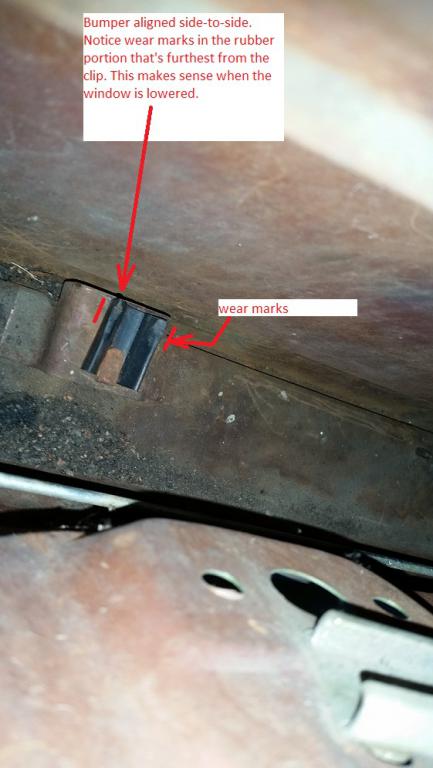
FWIW, I ended up mounting it sideways, and when the window is rolled all the way down the top of the glass is flush with the top of the outside rubber and inside "fuzzy" at the top of the door panel, so in my case I think side to side was the way to go.
-
I like that red you have, and would lose the stripe as others have mentioned. A gunmetal grey would look pretty bad ass, but I'd change out the interior to all black if you went that route. Add the LS1 in black on the side fender just below the body line. I am curious how that body kit has held up for you. Any regrets, "lessons learned" or wish you had picked a different style? Any issues with using a jack to get under the car? I am seriously considering going with either the one you have or the "stage 3" version from here http://www.thezstore.com/page/TZS/CTGY/classic02a01a since both my bumpers are shot, and replacing them would be about the same cost as the body kit.
-
I am the 4th owner, but the previous 2 were family members, and none of us have worked on the door or window (the car has been in the family since 1984). The first owner opened up the door to install some speakers, but other than that I don't think he messed with anything else. I did find a lock washer at the bottom of the door, so I will double-check everything (the window frame seems real solid though, so perhaps that washer was an "oops" from the factory).
-
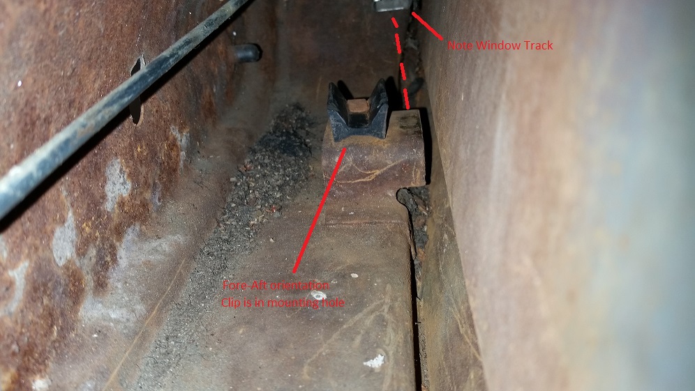
Hi z240, thanks for the reply. I tried mounting it like you suggested, but the window comes down next to it, not in the channel. The window rolls up just fine and seats into the frame perfectly, so I'm reluctant to mess with realigning the regulator to make it fit a fore-aft configuration with the bumper. In looking at the wear marks in the top of the bumper, it looks like it actually was in there as a side-to-side mounted part. I'm attaching pictures with some writing on them to show you what I mean. Does your Z have it's bumper mounted as you describe, with the window rolling up and down just fine? If so, I'll endeavor to re-align my track and mount the bumper fore-aft, otherwise I think I'll just mount this thing side-to-side and call it good.
-
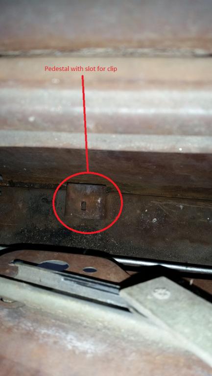
Greetings, I opened up my doors to try and address the window rattles and found the "Lower Door Window Bumper" (http://www.thezstore.com/page/TZS/PROD/30-2357) just laying loose at the bottom of both doors. I can't figure out where it is supposed to be attached. The factory service manual does not even mention this piece, much less show it. The one place that looked like it would be a logical fit was a metal pedestal of sorts near the rear of the door, that has a hole in the top that looks just about right for the clip, but when I tried it there and rolled the window down it wasn't even close to aligning with the "channel" that's in the bumper. Unless the channel isn't for nesting with the window? Is the bumper supposed to be aligned "side to side" instead of "front to back" (which was my assumption)? Any help is much appreciated, and pictures are worth a thousand words! Thanks in advance. 1973 240Z, build date 9/1973.
-
In the interest of completing and closing out this posting, after 2 moves (long story) I have finally gotten back to working on this car. I bought an internally regulated 60Amp 280ZX alternator and Dave Irwin's voltage regulator bypass plug (www.datsun-240z-upgrades.net) and guess what... it works! Perfectly! The Amp gauge shows a small amount of charge right after starting the car, as one would expect, and not the massive overcharge I was getting before. Conclusion: The external voltage regulators that the parts houses (NAPA, O'Reilly) are stocking are NOT CORRECT. The plug may fit, but the guts are not proper for this car. By the way, I cannot say enough good things about the quality of the stuff that Dave sells. In addition to the bypass plug I bought his headlight relay harness and parking light relay harness and the side marker conversion plugs. I have yet to install all this stuff, but the quality and attention to detail is first rate. I'd say "better than OEM". If you are sitting on the fence regarding spending the money, DO IT!
-
Hey Tony, I know we are drifting off the original posted topic here, but my 73 still has the egr hooked up, along with the smog pump. The dome tops are bolted onto the 73 intake, so the hot water under the carbs has been removed since these carbs don't have the provision for it in conjunction with the 73 manifolds. From what I think you have stated above, having the EGR with dome tops is a GOOD thing, but if I had the flat tops on it, then the EGR would be bad? I will say that the car does run very smoothly once warmed up, and pulls nicely, but then I don't have any other 240Z frame of reference to compare against, this being my first one. Helghast7: Actually , there was a Mazda Rx-5. Except here in the US it was called the Cosmo. I *think* all their rotary cars started with an R designation. Perhaps X was for "eXperimental" and the number was for the series. Rotary eXperimantal series 7 = RX-7?
-
Hey thanks guys! I didn't know about the supplemental manual, so that is a tremendous help to me. Tony, my 73 as I recieved it had been modded at some point in the past so I don't have an electric fuel pump, just the mechanical pump, and I have the earlier "dome top" carbs instead of the '73 "flat top" carbs (although I do have those in my spares box). After seeing all the tweaking and fiddling that supplemental manual has in regards to those "smog" carbs, I am very glad that they were replaced! If I ever decide to go with an electric pump I will definately go with the inertial switch. djwarner: I took a good hard look by my horns, and noticed a "lump" near each one in the harness. After unwinding a bit of the tape I found the bullet connectors for the fog lights! Thanks for the tip, I wouldn't have thought to dig into a taped up harness if you hadn't mentioned it. Anyone know where they put the switch for the fog lights in the JDM and/or Euro models?
-
Tony, that sounds increadibly dangerous to me because if you get in a wreck the pump will keep working until you turn the key off! My '73 has a wiring harness that connects to both the starter solenoid and the voltage regulator, and drives 2 relays. I believe the starter solenoid will pass power to the first relay, and therefore the pump, then the VR signal triggers the second relay to keep the pump running. In the event of a crash the engine (and therefore the alternator) stop, which kills the power to the relay, and kills the pump, preventing gas from continuiing to spew all over the (hopefully not flaming) wreck that used to be your car. For safety sake I urge you to reconsider how you have that wired up... use a relay hooked to the oil pressure sending unit or something. I know there have been write-ups both on this site and on the ClassicZcars forum on how to do this. Please be safe!
-
Oh yeah, getting back to my original post, does anyone have any other observations regarding the FSM wiring diagram showing things that either don't exist on a North American car (like the fog lights), or that are just plain wrong? I know they did running changes as the year went on (notice the horribly innacurate wiring diagram for the electric fuel pump system!), and they probably produced the FSM before some things were finalized.
-
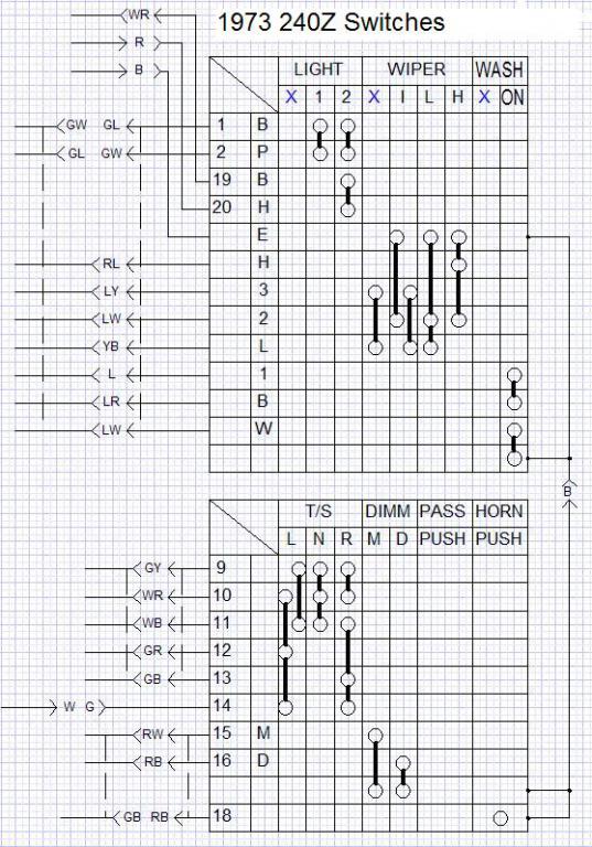
OK, I found on pages BE-22 and BE-23 a nice description of the combo and dimmer switches, and it answered my question regarding the red H... it is a B after all. I have updated my diagram, and am attaching here for everyone to use. Blue X = "OFF". You may notice that some connections show two different wire colors, (numbers 1, 2, and 14). This is not based only on the FSM, but rather what is in my car as well. I have several electrical issues with this car, so I figured I'd start my own wiring diagram to document what I have, and then compare that to what is in the FSM. Between the missing stock (and aftermarket) radio, the missing dealer installed AC, and the interesting anti-theft "hidden button that must be pressed" to start the car (that the original owner put in, then my brother bypassed, but left in place), not to mention 40+ years of wear and tear, corrosion, etc. it's little wonder that I'm having some issues. In fact, I'm kind of surprised I'm not having more issues than what I have!
-
Tony, you have probably hit the nail on the head with it being a translation issue. Although, I was looking at the '74 wiring diagram for the headlight circuit, and they actually label the high beam indicator lamp as the "Main Beam W/Lamp" and the high beam switch as the "Turn Signal Dimmer Switch". Which leaves me wondering if the Japanese normally drive with their high beams on all the time, and occasionally "Dimm" them for the oncomming traffic. So I'd say at this point that M=Main (high beam) and D=Dimm (Low Beam). I have looked in the FSM for the pin numbering explanation, but haven't found it. What page is it on? Dom, I think you are probably right... it's total pins all together and not per connector. P seems to energize the dash lights if I'm reading this blurry mess correctly (or is it my eyes are just crappy?). The top B traces to the under-hood inspection lamp, the other B traces to the map lamp, so yeah, perhaps it does corrospond to BATT+. The only question I have left now is my red "H" in the combo switch. I *think* it may actually be a B from looking at the '72 wiring diagram, but it may also be an E. It's really hard to tell because my manual and the down-loadable PDF's are all kinds of blurry in that area of the chart. Does anyone out there have a better copy?
-
Hey guys, I could buy the numbers=pins if the numbers and numbers-of-pins agree. I just don't see how you could have a pin 11 on a 9 pin connector. In my 30 years as a design draftsman (many of them doing schematic work), I have never seen electrical connectors have pin numbers that were totally off from the pin count. I have seen connectors use letters, numbers, and combinations of letters and numbers, but never arbitrary numbers. According to the wiring diagram and the body harness drawings, the largest connectors we have in these cars only have 10 pins (at least on the 240). Therefore there should not be any "number 11" or higher (the way I see it). That's why I put the shout out for help, because what's in the FSM just isn't making sense to me. Perhaps I am trying to read too much into these numbers, and they were just meant for some sort of internal Nissan technical document, and not for us "owners". Page BE-19 in my manual shows the windshield wiper/washer schematic in more detail, and there are numbers (1, 2, 3) and letters (W, L, H, E, B, P) that I can see corresponding to the attachment in my original post. (W= Wash, L=Low, H=High, E=Earth (ground))... But what do B and P stand for ? Then there is the turn signal/high beam switch. For the turn signal column, I figure L=Left, N=Neutral (centered), R=Right. The "DIMM" column is for the high beams, I am thinking M=Maximum (high beams on), D=Drive (normal headlights). This is based on following the RW wire that is associated with M up to the speedometer where it looks like it is connected to a lamp (high beam indicator?). I think the "PASS" column may be referring to a JDM or Euro spec car that would have a momentary "flash to pass" feature found on newer cars, but since our US spec cars only have a pull-click-on/pull-click-off high beam switch we don't have any dots in this column. (But if they were going to do a U.S. specific wiring diagram why didn't they remove the fog lamps and step lamps from the diagram? ) That last column that I have labeled "HIGH" in red I now think should be "HORN". If you follow that GB wire it ends at the horn relay. Seeing as the physical switch does include the horn conductor that contacts the center pad, I guess I can see why they included the horn into this diagram. Hey Tony, I found in my FSM the wiring diagram for the automatic equipped car is less blurry than the one for the manual transmission. Perhaps yours is the same? I hope I didn't come across sounding like an argumentative SOB. That was not my intent! I really appreciate all those who take the time to read the post and offer suggestions. So Tony and Dom, thank you very much for your input. Perhaps we can get this sorted out so that when others browse this topic looking for answers we can have something solid for folks to refer to.