
Miles
-
Posts
2374 -
Joined
-
Last visited
-
Days Won
29
Content Type
Profiles
Forums
Blogs
Events
Gallery
Downloads
Store
Posts posted by Miles
-
-
Headlight relay harness built by a HybridZ member (HLS30-08077) and sold by MSA:
http://www.thezstore.com/page/TZS/PROD/12-4651
Or buy direct from Dave (HLS30-08077):
https://www.datsun-240z-upgrades.net/product-info/
Works!
-
1. What year is your Z?
2. Did you check the fuse panel?
3. Typically, the problem you have is caused by the turn signal and/or the light switch. Many "how to" posts on switch repair here and on the internet.
4. Information:
http://woodworkerb.com/home/datsun-240z-rebuild/datsun-240z-multifunction-switches/
https://www.datsun-240z-upgrades.net/services/
https://fiddlingwithzcars.wordpress.com/2012/12/04/turn-signal-repair/
http://www.classiczcars.com/forums/topic/34330-72-240z-turn-signal-stoped-workining/

-
 1
1
-
-
2 hours ago, 5 Star Rising said:
Still haven't had time to pull my carbs, but do you think that because one of the pistons has more resistance going up than the other carb that it may be the issue?
Last weekend I got some needles and the complete bottom seat assemly off a 72 240 that was completely rusted in rotted out including the carbs or at least they looked pretty beat. I have yet to take my carbs out and swap the needles and seats but at least now I have something to try. And now you got me thinking about the Pistons.
-
Possible mismatch of clutch parts e.g., 240z - 280Z throughout bearing components.
Do a Google search or HybridZ and search for 280Z transmission swaps.
Also, this issue has come up before so there should be some info here or at one of the other Z blogs.
Check the FSM for a 240Z and 280Z transmission.
-
With the engine off, place firm pressure on the brake pedal and hold that pressure.
While holding pressure on the brake pedal start the car and post what your foot does.
-
The mounting hole pattern on the 240Z and 280Z are different. The horizontal spacing of the mounting studs is wider for the 280Z so I had to re-drill the mounting holes in the fire wall.
It has been eight years since I was working this issue, but I recall the that the 280Z and 280ZX bolt spacing is the same.
If you have a 76 280Z then your booster is most likely 8.5 inch diameter. And you should already have an 8.5 inch booster installed.
Time to measure the booster you have and also measure the space between the throttle bracket and the clutch slave. That will determine what diameter booster you can use.
If you have an automatic z then the clutch slave is no factor and you could install the 10 inch 280ZX booster.
-
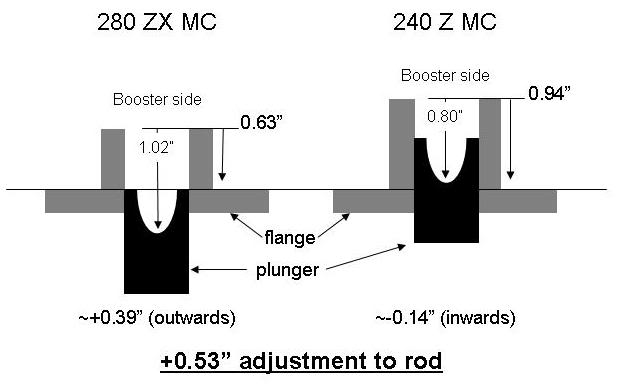
The 75 - 78 280Z came with a 8.5 inch booster which is what I am using on my 72 240Z with 15/16 inch. The larger 8.5 inch 280Z booster made the pedal less stiff. I would like to have used the larger 10 inch 280ZX booster, but there was no room between the throttle bracket and the clutch slave. See pictures.
The space between the throttle bracket and the clutch slave is the limiting factor. The 280Z has more space between the throttle bracket and the clutch slave so a 79 280ZX booster might fit. I recall that the 280ZX booster is 10 inch diameter. The 80 -83 280ZX booster uses a horizontal MC mounting flange whereas the 240Z, 280Z and 1979 280ZX use a vertical mounting flange.
I had many Hybridz links on booster swaps, but the links are now dead.
Note that there were changes in mounting bolt patterns and the clevis that connects to the clutch pedal. I swapped the push rod and clevis from the 72 booster to the 280Z booster so everything matched.
-
20 hours ago, M_Motorsports said:
Can a reverse bleeding tool work where you force brake fluid from the calipers back to the MC?
Can this eliminate the air bubbles that are somehow trapped in the calipers back thru the system? Yes, as long as the bleeders are pointing up so air is not trapped. It will not help if there is still air trapped in the MC.
Have one available from a friend who uses one when he bleeds his brakes alone.
1. Set all of the mechanical brake adjustments, including the push rod, correctly. See push rod length adjustment above. You can do fine adjustment to the rod after the car is safe to put on the road without removing the MC.
2. Bench bleed the MC. Take your time and get all of the fine bubbles out. Make sure none of the fittings or plastic lines are sucking air. Transfer the MC to the car with the outlets plugged. Attach MC to brake lines loosely and then to the booster. Tighten the brake line fittings after the MC is attached to the booster.
3. Bleed brakes with a helper or use speed bleeders (check-valve style) or use a Motiv pump bleeder (what I use). The pump bleeder works well, but can be messy.
On some calipers you have to remove the caliper, block the pistons, and shake/rotate the caliper while bleeding to get the air out. Be sure to block the pistons. If you don't block the pistons you will be very sad.
-
The piston needs to go full stroke.
-
Did you bench bleed the MC?
-
When bleeding calipers make sure that the bleeder is pointing up and not at an angle to get all of the air out.
-
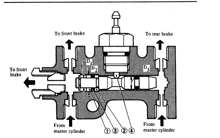
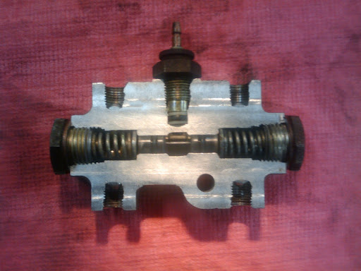
The device under the MC is called a "differential pressure switch". In the event of front or rear pressure loss, it shuts off fluid going to the circuit that has the lowest pressure i.e, a leak.
It also serves as the distribution block for the front and rear brake lines.
When a leak occurs a shuttle inside the valve moves to the lower pressure side of the switch to stop fluid flow and the shuttle touches an electrical contact that turns a red light light on your dash. That is it. Leave it alone. See pictures.
The calipers you installed require more fluid hence the longer pedal.
If you have to pump the brakes then you still have air in the system.
Recheck all of the mechanical linkage adjustments including the MC push rod and re-bleed the brakes.
-
Are you over thinking the problem?
- Research the function of a thermostat.
- I see you are in the Bay area where it tends to be cool. You haven't mentioned what the air temperature is when the water temp appears too cold.
- What are the temps on a 90 - 100 deg day?
- Perhaps you need to calibrate your temp gauge and sender by measuring actual water temperature with a digital thermometer (meat thermometer works). Place the probe between the fins close to where the return hose connects to the radiator.
- Could be that you just have an efficient cooling system!
-
Had similar problem on my first 240Z. I just took it to a "sun/moon roof shop and they matched the existing unit. Or you can measure the hole and research a replacement on-line.
-
-
Boy
I don't know what Wilwood's problem is with making 10mm x 1.0 inverted flare adapters. A lot of Japanese cars use inverted flares.
-
41 minutes ago, Boy from Oz said:
I looked at this a long time ago. It is 10mm x 1.0 bubble flare.
From Summit:
Q: Is it an inverted flare or bubble flare on inlet and outlet?
Asked by KENNETH on June 02, 2016
A: Thank you for your question. Wilwood Disc Brakes 260-12627 would have a 10 mm. x 1.0 bubble flare on both inlet and outlet.In 09 I checked with Wilwood. They had no interest in supplying 10mm x 1.0 inverted flare adapters or a PV with those specifications.
-
Flyn Miata metric to NPT adapter
Flyin' Miata Search results for: 'M10 inverted flare to NPT adapters'
-
1 hour ago, Boy from Oz said:
Why not buy the metric version of the valve which has the 10 mm threads?
The less number of fittings, the less chances of leaks.
Do you have a source for a metric PV?
-
Look here also:
http://brakequip.com/products/hardware/male-female-adapters/
http://www.lowrangeoffroad.com/suzuki-off-road-parts/sidekick-tracker-x90/brakes.html
Had the same problem years ago:
-
I am seeing a lot of references to bubble flares.
Z cars should all be 10mm x 1.0 inverted flares. Bubble flares on a Z will leak.
-
1
-
-
19 minutes ago, Michael said:
Not to be the acerbic dissenter here, but sometimes it is more satisfying (not to mention, more illuminating) to get components that are of marginal robustness, but which are standard, common and well-researched... try them out, see if they happen to work, and then replace if/when failure happens. Too often, we overbuild; we overspend, end up for example with a clutch that's too heavy to be comfortable, with a "bulletproof" transmission with heavy/cumbersome gear-engagement, and so forth. I personally made this mistake, in going with a Doug Nash 4+1 transmission... "bulletproof" indeed, but a chore to shift, with gears that are too closely spaced. At least the clutch was a success... Centerforce dual-friction; Hayes 168-tooth aluminum flywheel - both from the Summit catalog. The one semi-unorthodox piece was the McLeod hydraulic throwout bearing, obviating a clutch-fork or pivot point.
In sum, consider the typical small-block build from the Summit or Jegs catalog. It should work fine.
Well said. An over built car is expensive and can be miserable to drive.
-
Check the steering rack bushings. They are inside the clamps that bolt the rack to the cross member. The originals are rubber and wear/rot out which allows the rack to move. If the bushings look worn, or there is any movement of the rack while moving the steering wheel, replace the bushings with polyurethane bushings.
Also, failed rubber tension/compression (T/C) rod bushings can cause the car to dart under braking and to drift left - right. Do not replace the T/C bushing with polyurethane as it is too stiff and can cause failure of the T/C rod. Replace with stock rubber bushings only.
The polyurethane and T/C rod bushings are available from Motor Sports Auto (MSA).
-
JUst go to the parts store and buy an electronic flash unit. It looks like the stock flash unit except it has a ground wire . Thats it. There are also electronic flashers that have an adjustable flash rate.


Fuel tank vent / Evap tank / EFI question
in Fuel Delivery
Posted · Edited by Miles
What year Z would help.
You will need to keep line 8 or line 7 and route it to where line 5 attaches to the filler neck in the picture below.
Look at the picture and you will see why you need to keep the line in addition to venting the tank on hot days.