nismo kid
-
Posts
529 -
Joined
-
Last visited
-
Days Won
4
Content Type
Profiles
Forums
Blogs
Events
Gallery
Downloads
Store
Everything posted by nismo kid
-
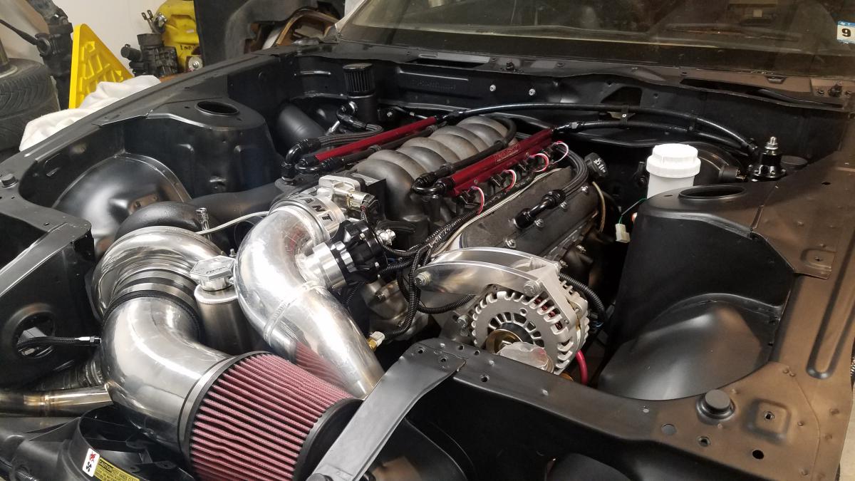
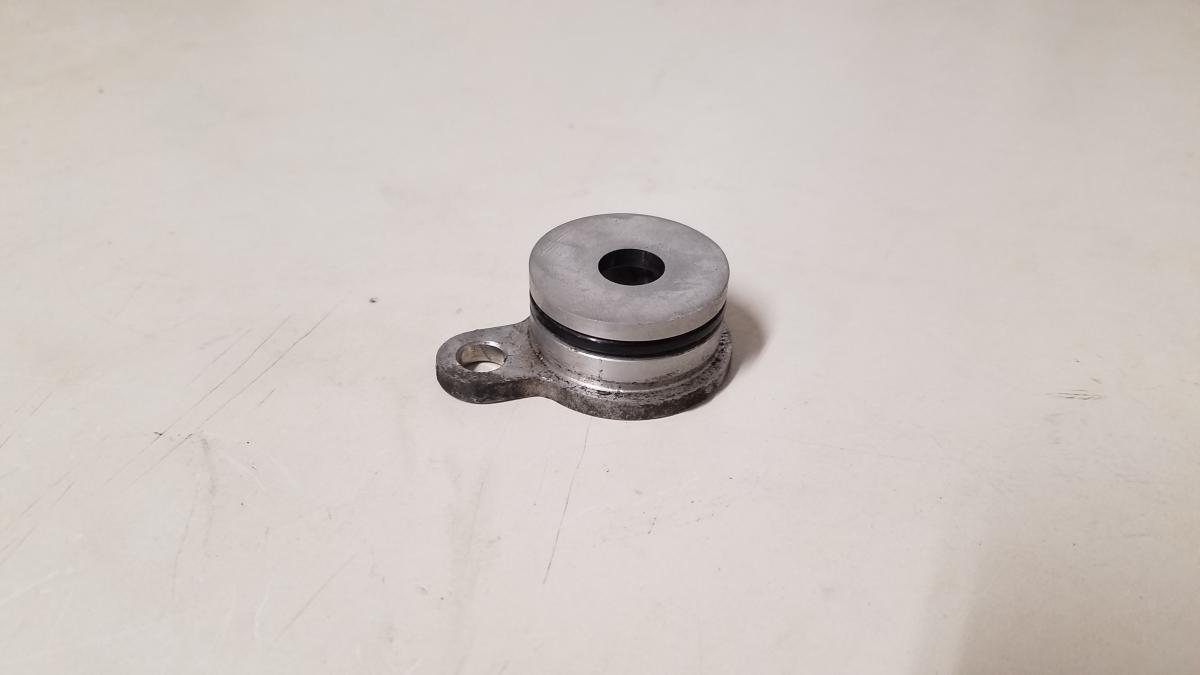
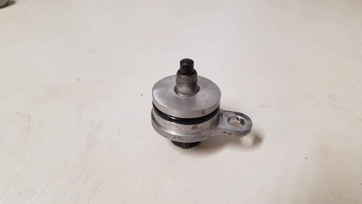
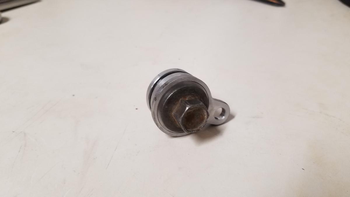
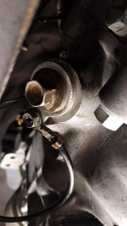
A sensor to monitor fuel pressure was also added to the fpr. I used a Honeywell 150psi transducer part# PX2AN2XX150PAAAX. I tried a budget unit from amazon but it kept giving me sporadic results no matter what I did.
-
While tuning my car one day, I ran out of fuel due to the lack of a fuel gauge. The factory sending unit & gauge cluster in my car were inoperative when I purchased the car. So a Intellitronix LED analog bargraph gauge was added. Intellitronix appealed to me because it's made in the USA, they have good customer service, I liked it's appearance & price point. As for a fuel sending unit a Bosch unit (part# SP0F000013) was chosen. The factory sending unit was stripped down & the Bosch unit was modified to fit it. I even retained the factory plug. A yellow w/red stripe wire was used for the fuel gauge signal wire. This wire can be found on the left(driver) harness near the dead pedal.
-
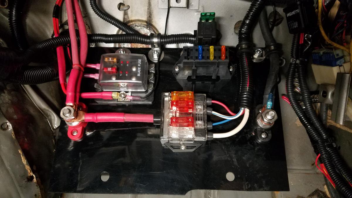
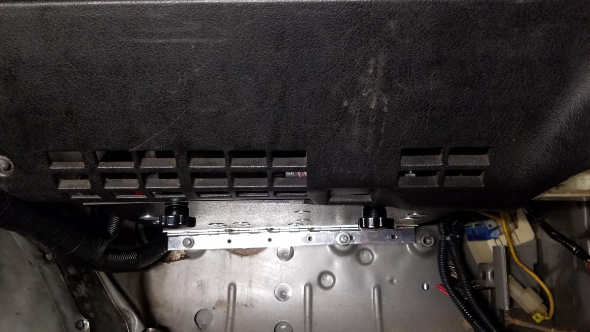
I felt my previous breaker & relay setup looked too "busy". This was easily cleaned up by making a new panel for them to mount to. The panel also has extra room for future breakers. Previous setup New Setup Another fuse box was added to the mix. Knowing more devices would inevitably find their way into the build & would need a fused power source. I wanted all my additional fuse boxes to be in the same general area (above passenger foot well). Space was an issue. 1/4 inch ABS plastic was used to create a panel for the additional fuse box & ground distribution block. A stainless steel piano hinge was attached to the panel. Which allowed it swing down from underneath the glove box. The breaker & relay for the fuse box was also be mounted to this panel. A magnet prevented this panel from swinging down unexpectedly. With swing down panel completed, power & ground wires were ran to the rocker switches. Additional LED's were installed for the line lock, 2 step & data log switch. The line lock LED is solid red when active. The 2 step LED flashes red when active. As for the datalog LED it flashes blue when active. To make the leds flash, I used CEC Industries EF32RL Electronic LED Turn Signal Flasher Relays.
-
Long time no post huh? Don't you guys & gals think I've forgotten about updating this build. I've been super busy but we'll let you be the judge. This is 7th major update entry in this build thread. As any other good read this update is filled with plenty of ups & downs. To kick it off the realization several switches were going to be required to activate/trigger devices that were to be installed. Originally I wanted to repurpose the factory headlight wash, heated mirror, & adjustable suspension switches but my shifter location axed that idea. I chose rocker switches with built in LED’s. Then determined how many switches & how much real estate was required. These were functions/devices that would need switches data log, 2step, Line lock, & boost control. A AEM 12 position trim pot switch was selected for boost control. This way many different boost levels could be achieved with just a twist of a knob. 7 Rocker switches would suffice for the rest & leave extras for future use. The A/C control panel is easily accessible by the driver & wasn't needed. It's location was perfect. With all my switches chosen, I disassembled the A/C control panel saving just the "case". Which was trimmed down to accommodate the switch wires. 1/4 inch ABS plastic was used to make a faceplate that would hold the switches. I drilled holes into the faceplate after the orientation of all switches were determined. To attach the faceplate & case blind holes were made on back of the faceplate. So screws could secure them together. The trim pot switch came with stickers that numbered all 12 positions. A area the same size as said stickers was routed smooth to prevent them peeling from the faceplate. Then switches were installed into the faceplate.
-
Thanks for checking the build out. There should be a another update in the near future. I'm just button a few things up.
-
At this point the only things that needed to be taken care of before the 1st drive was the bleeding of my clutch & brakes. With the help of my lovely girlfriend that was quickly knocked out. My goal was to drive my car before 2018 came. Motul 8068HL RBF 600 DOT-4 was used for my brakes & clutch. I also with switched my transmission fluid out to 50305 MT-90 75W90 GL-4. Now its the day of Christmas Eve. After double checking every nut & bolt I lowered the car down from the jack stands. Then I warmed the car up & began to adjust the tune. So I could actually attempt it's 1st drive. With the tune roughly adjusted, the car was ready to take out. Would it drive?..... or will I fail to meet my goal?....... Well I places my phone on a tripod & to record it either way...... Thankfully for me the car ACTUALLY DROVE!!!! There's still a ton of tuning left to do but I finally was able to DRIVE my car for the 1st time! I'm by NO means a tuner but I'm gong to give a try. I understand the drive isn't a very exciting for most but this was a huge accomplishment for me. I've included the videos below. This was a huge update! Sorry I wasn't able to release this update done than I did. It should be well worth the wait IMO. Thanks to everybodyfor all support & following the build! Stay tuned. https://youtu.be/DcMBSUcZv90 https://youtu.be/ChwRHIjSmJs https://youtu.be/TwGjmifHZ28

-
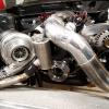
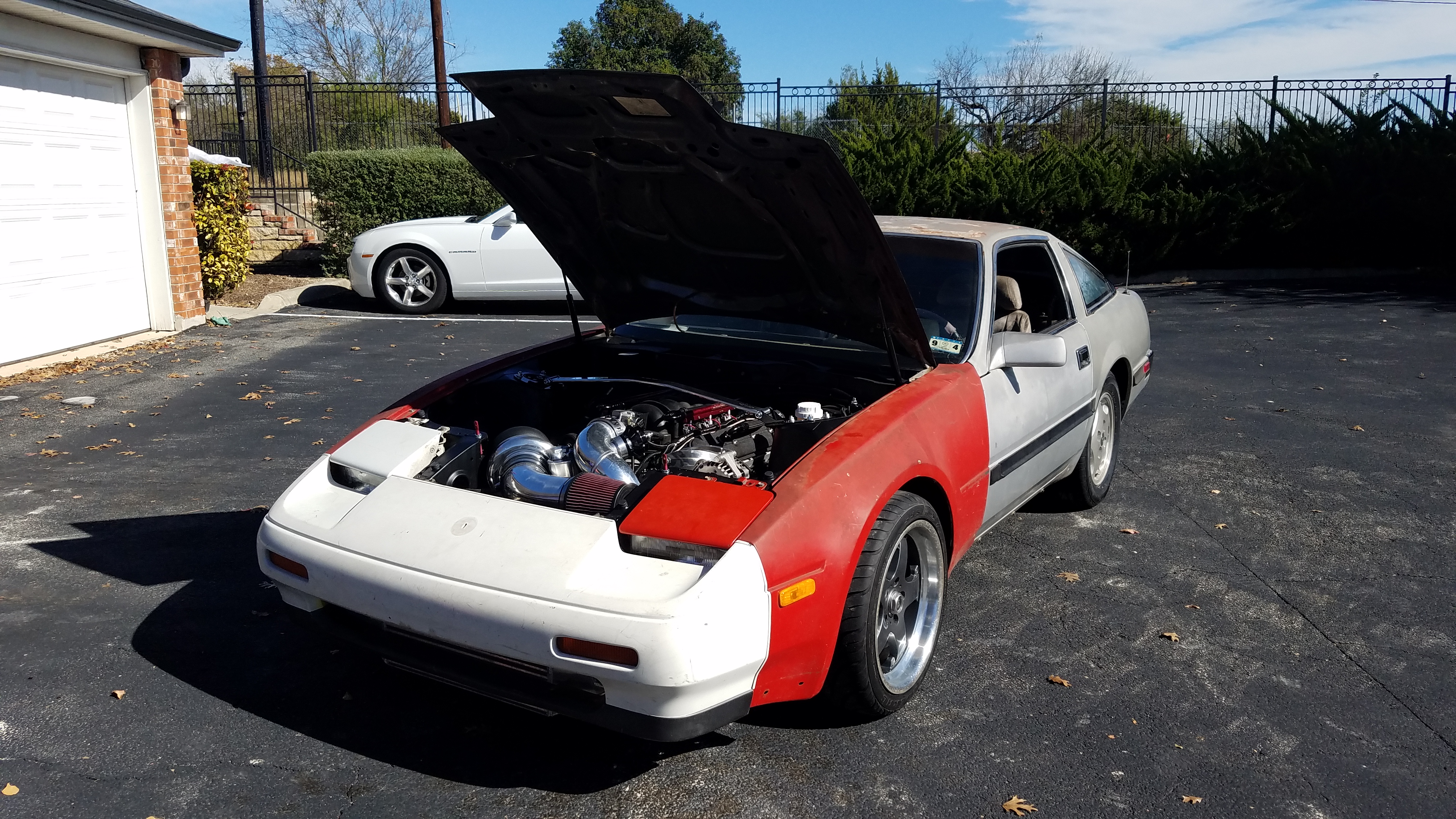
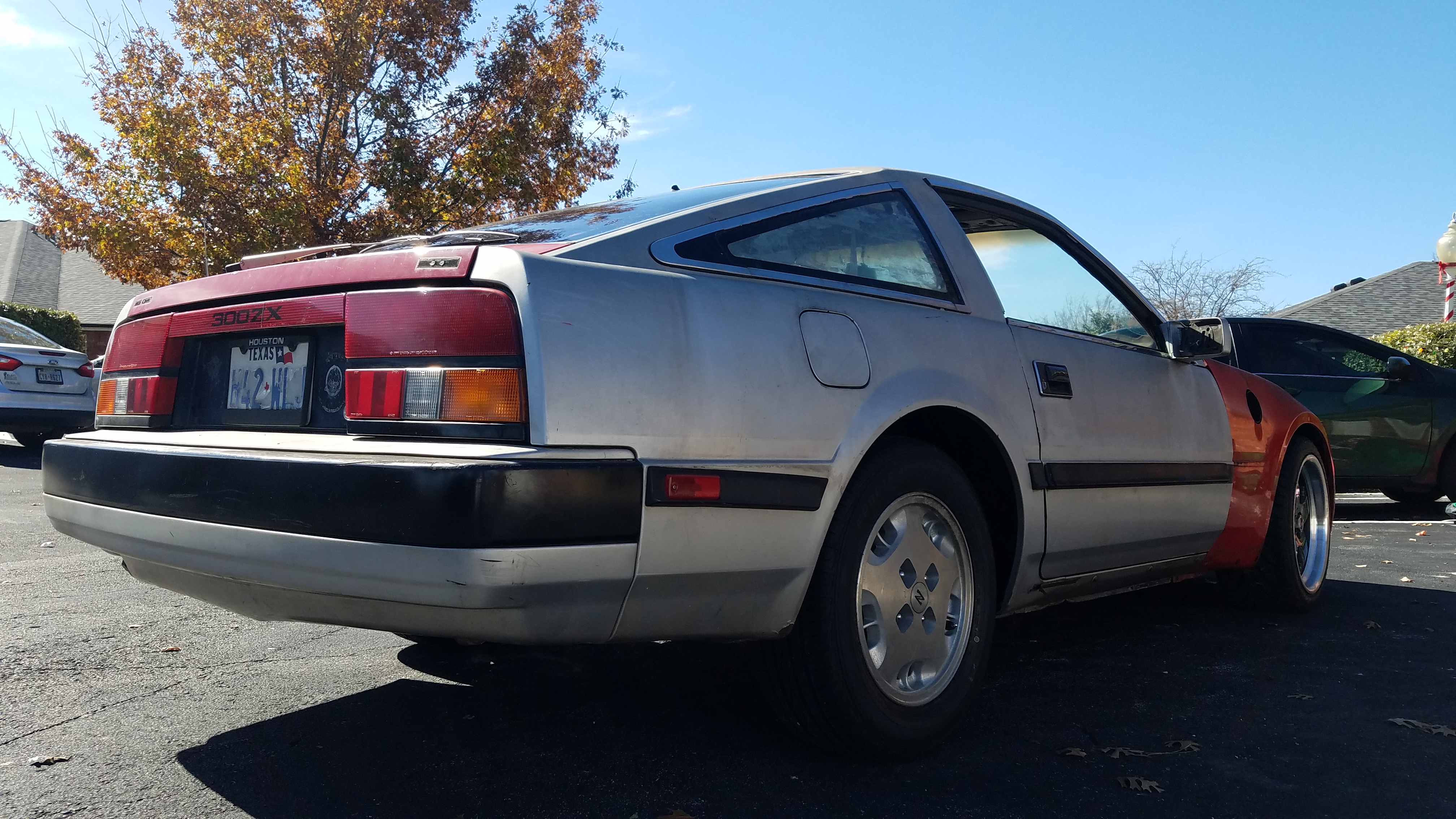
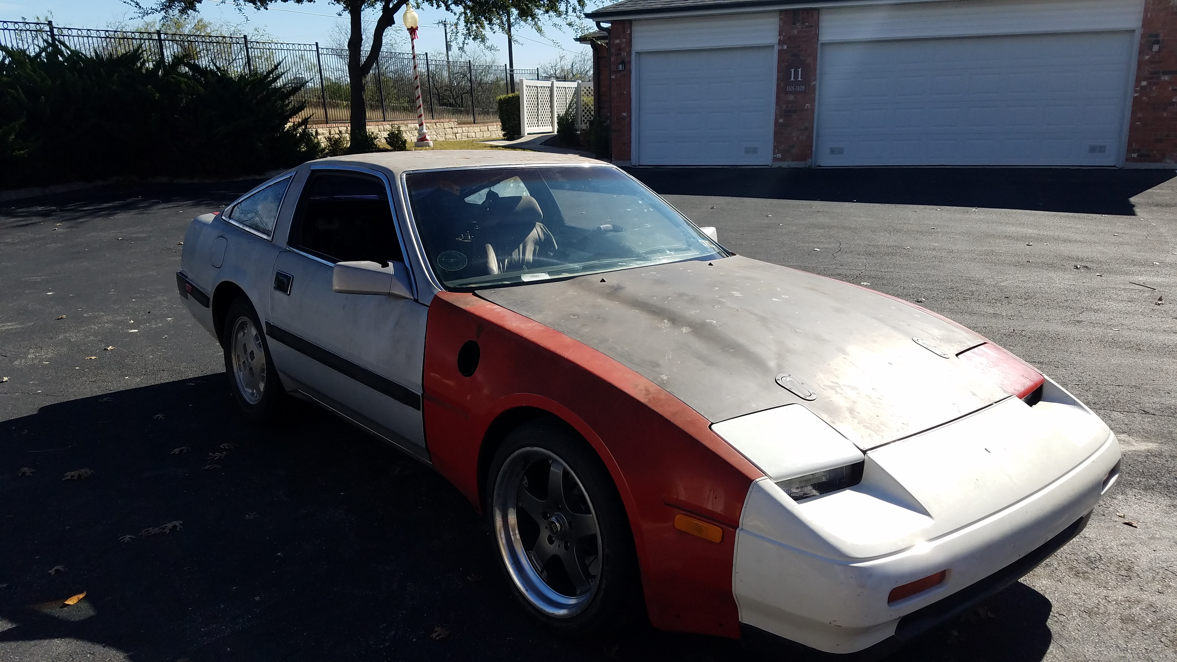
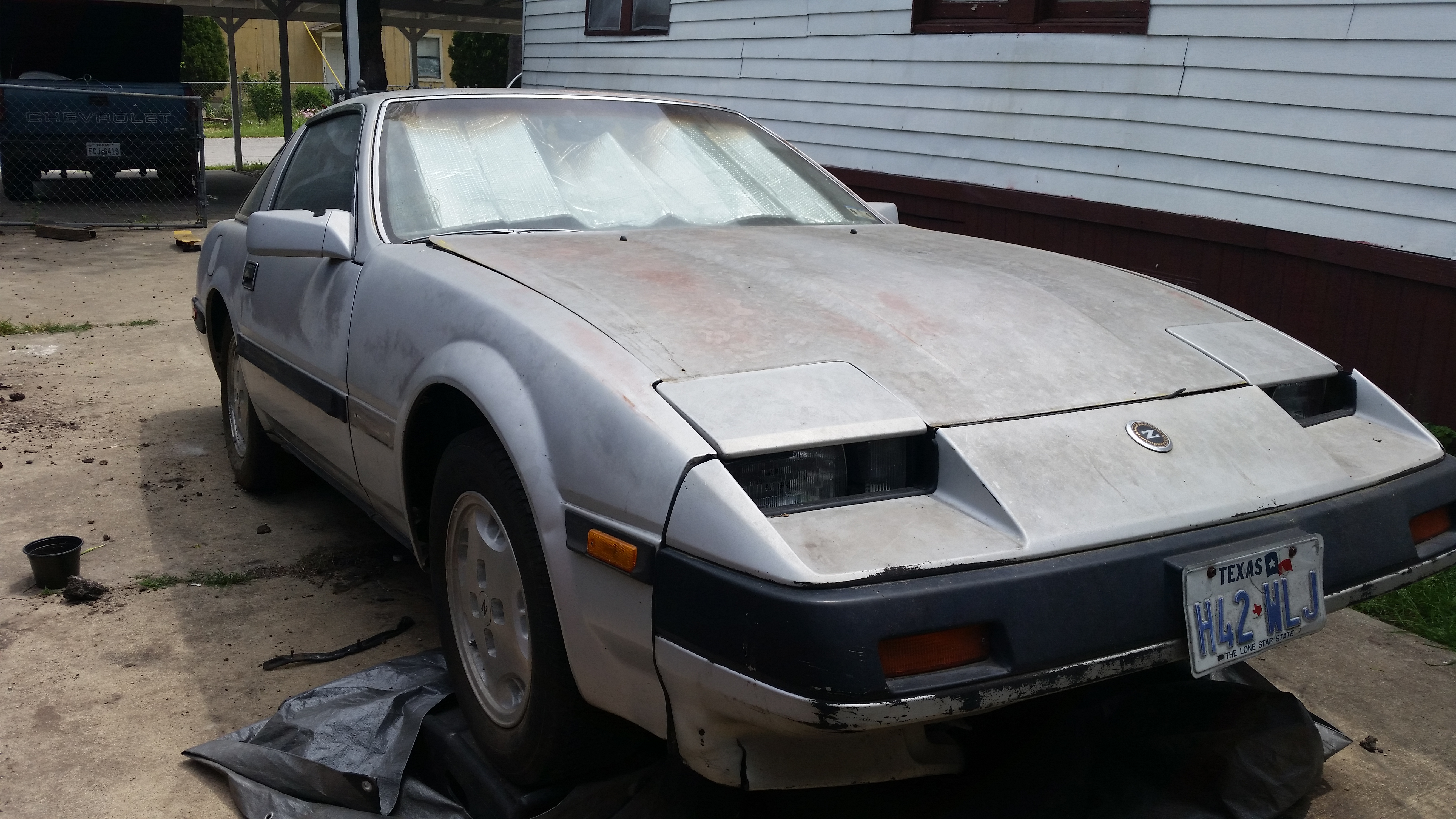
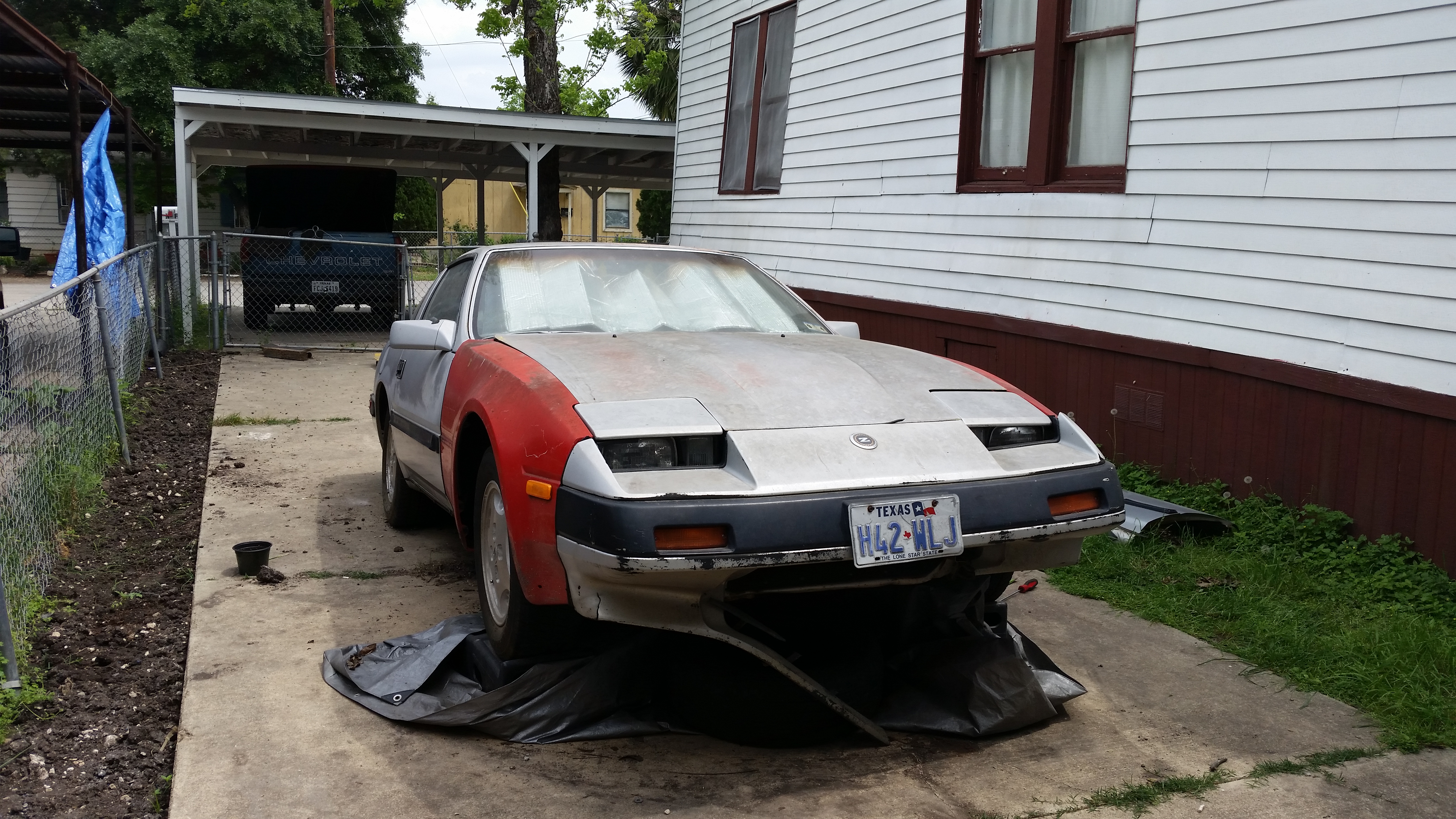
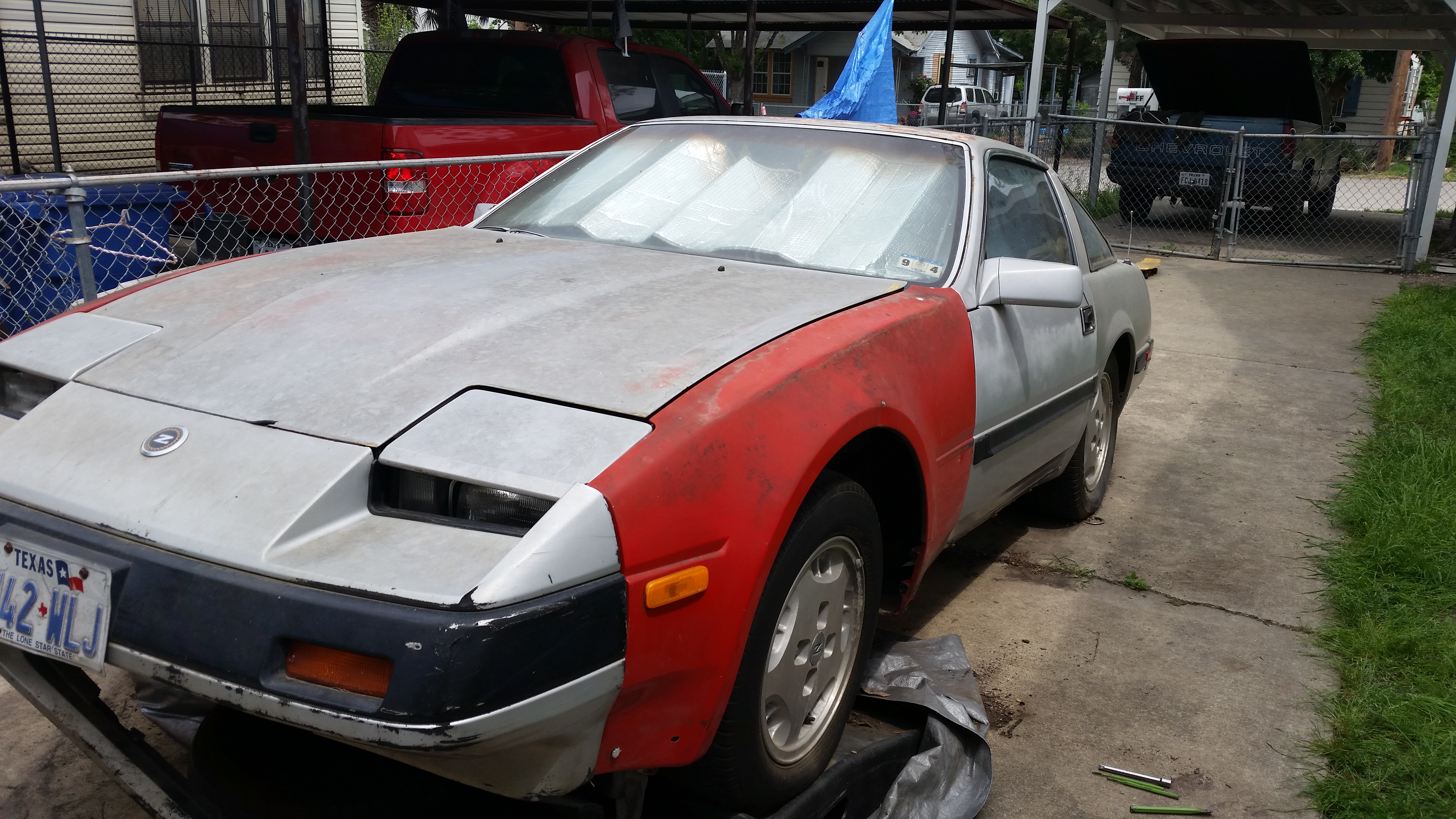
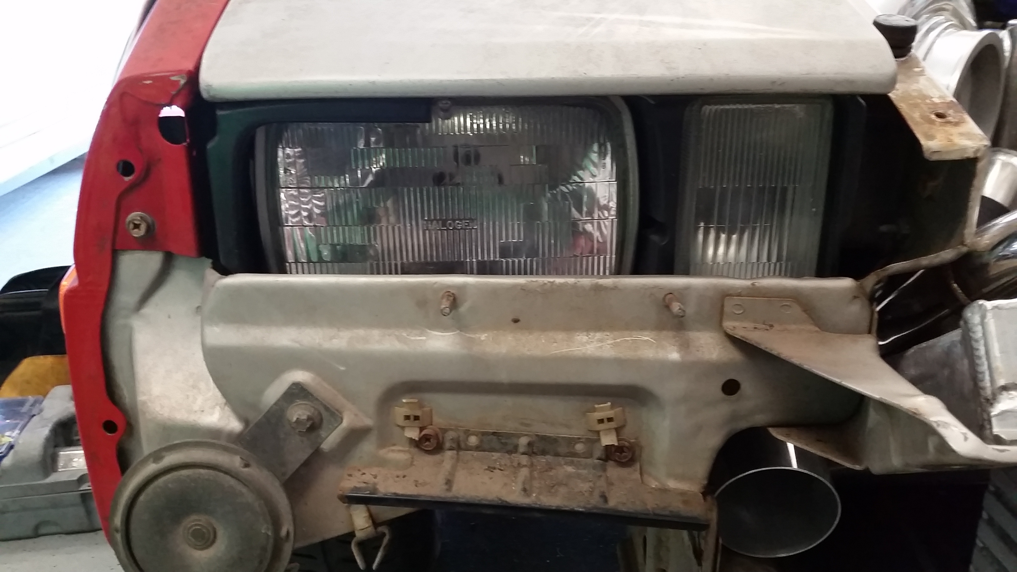
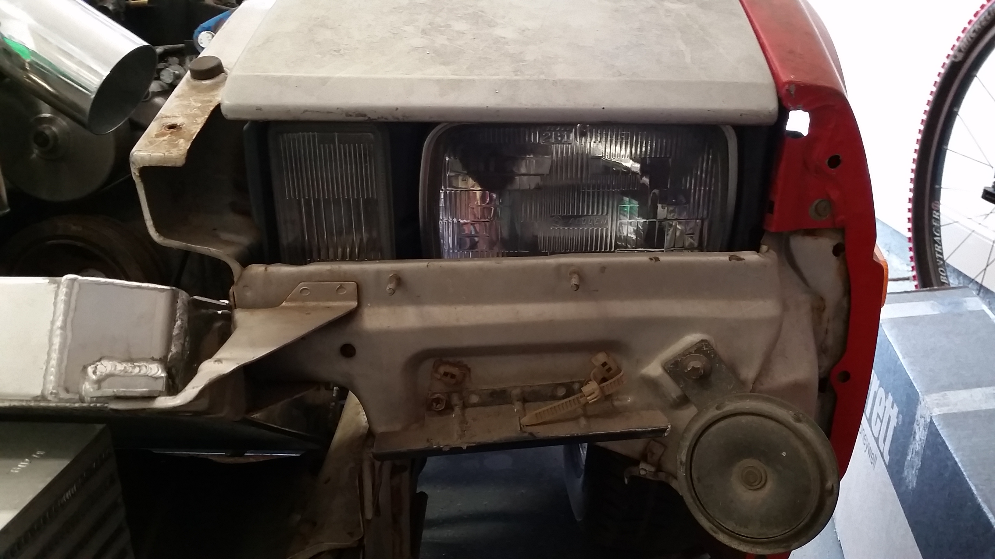
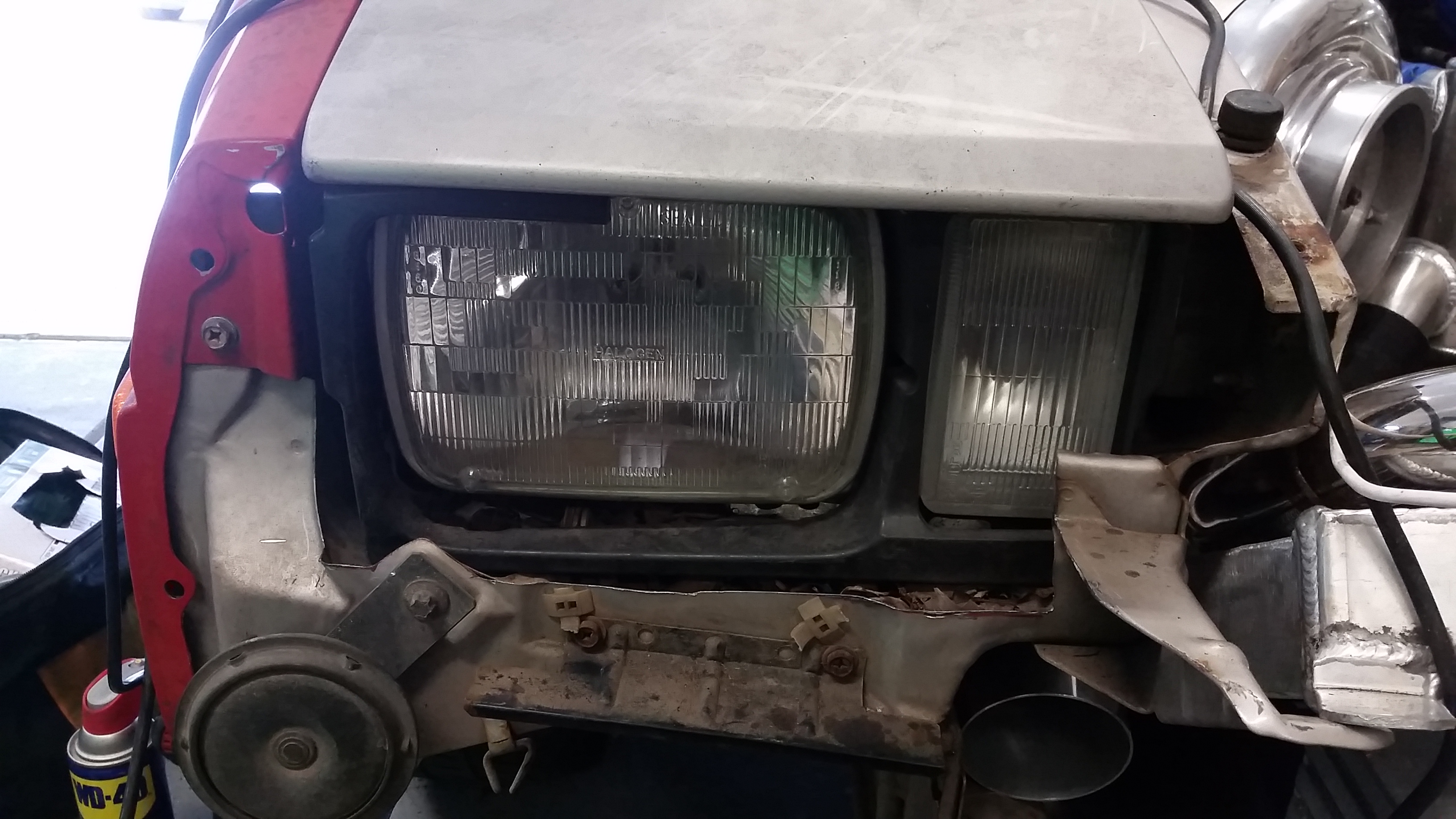
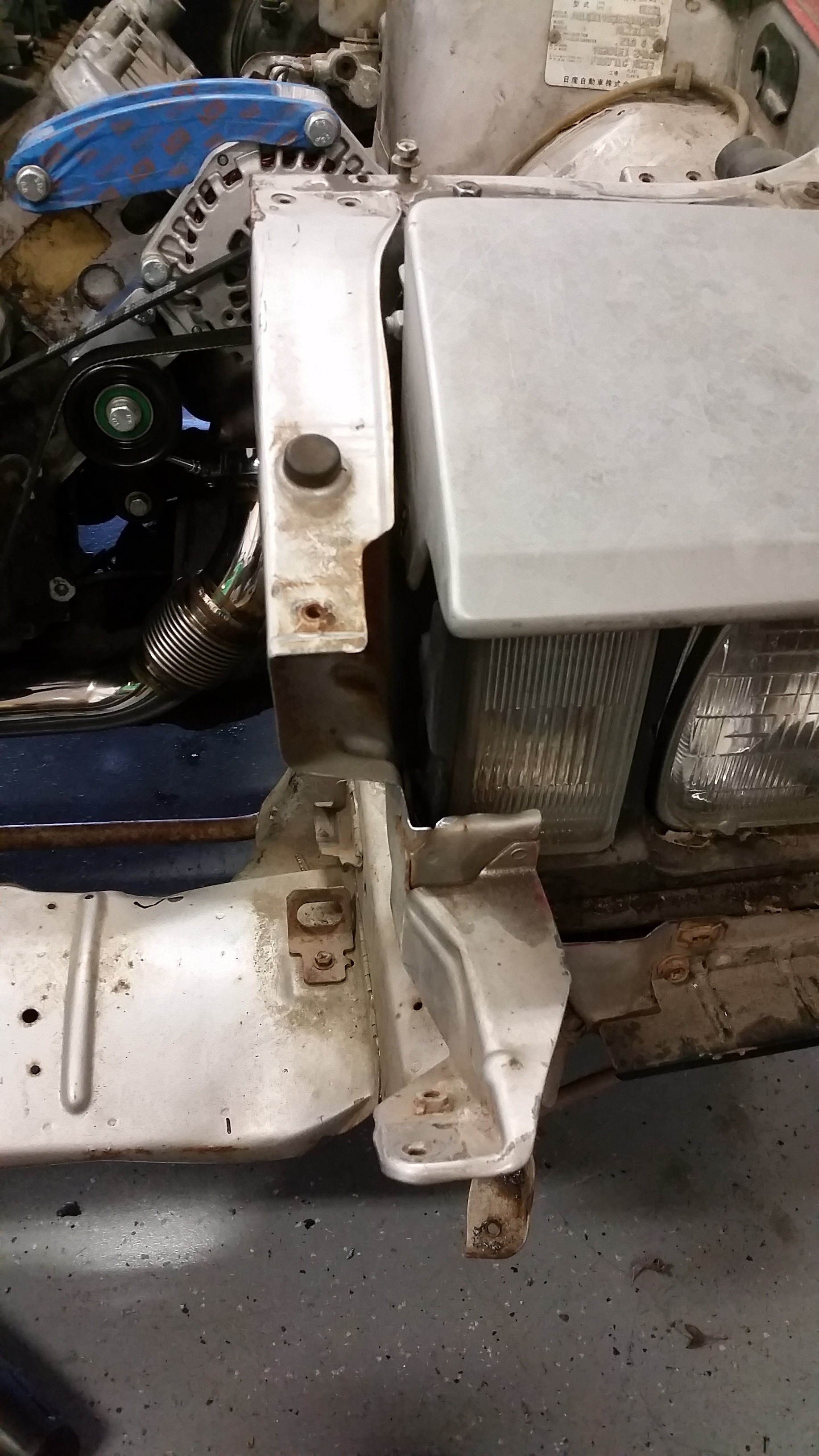
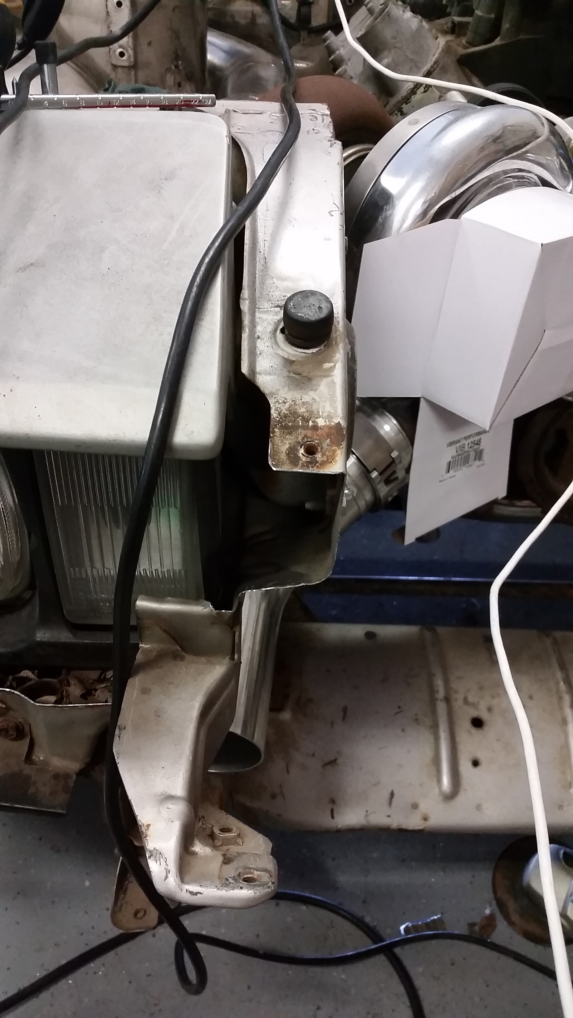
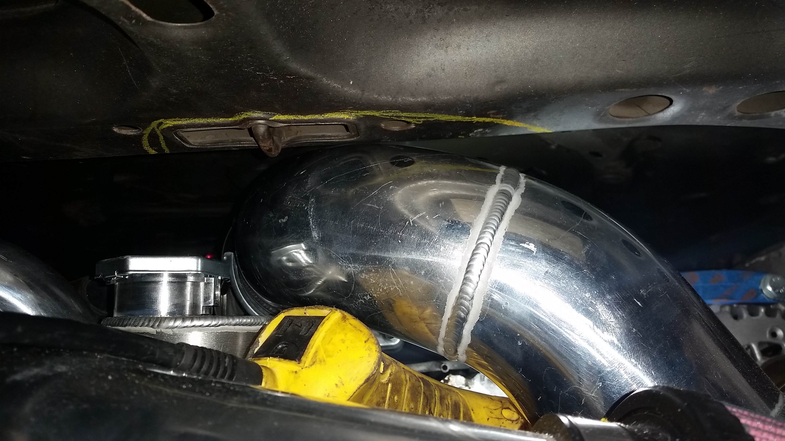
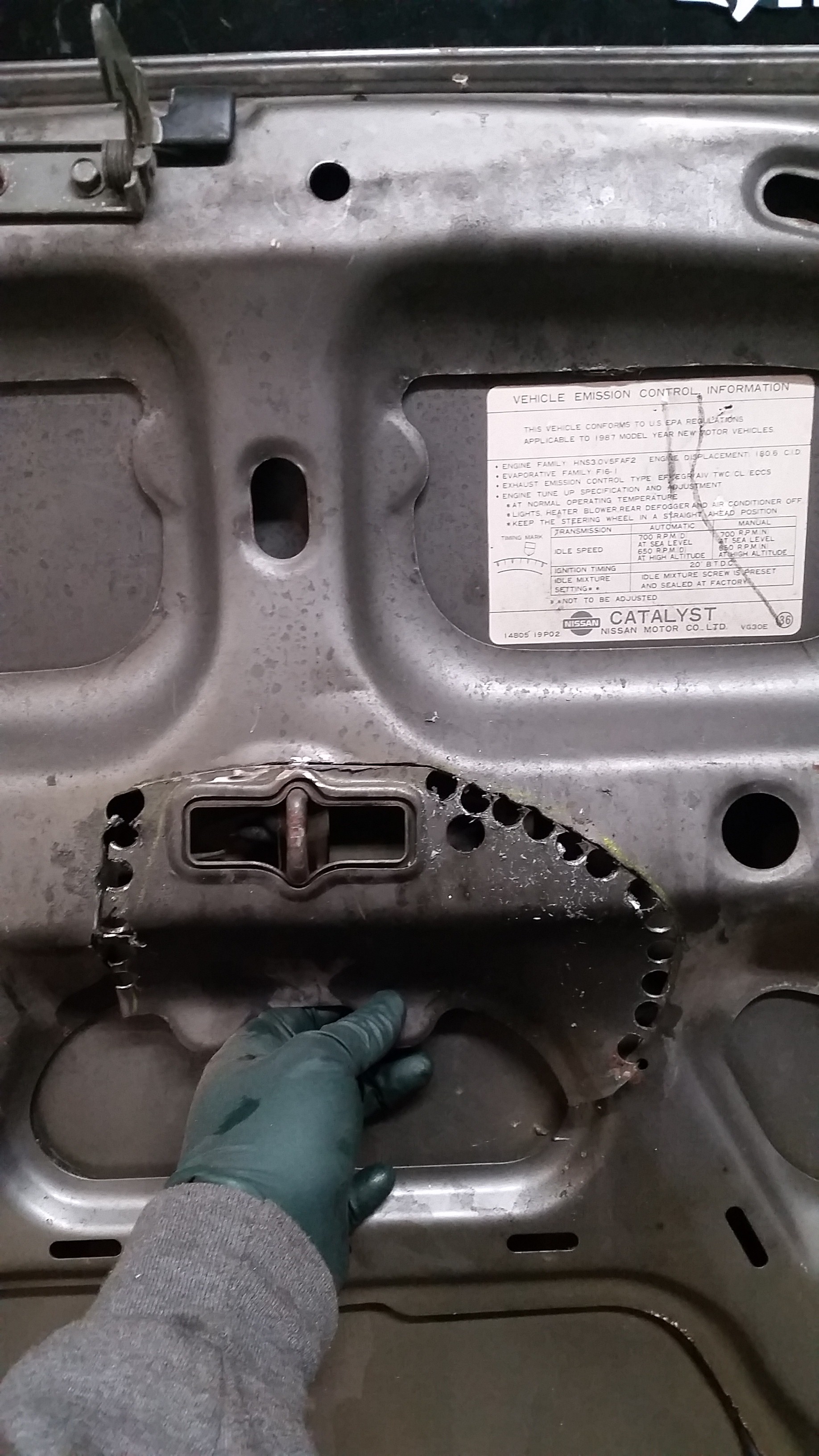
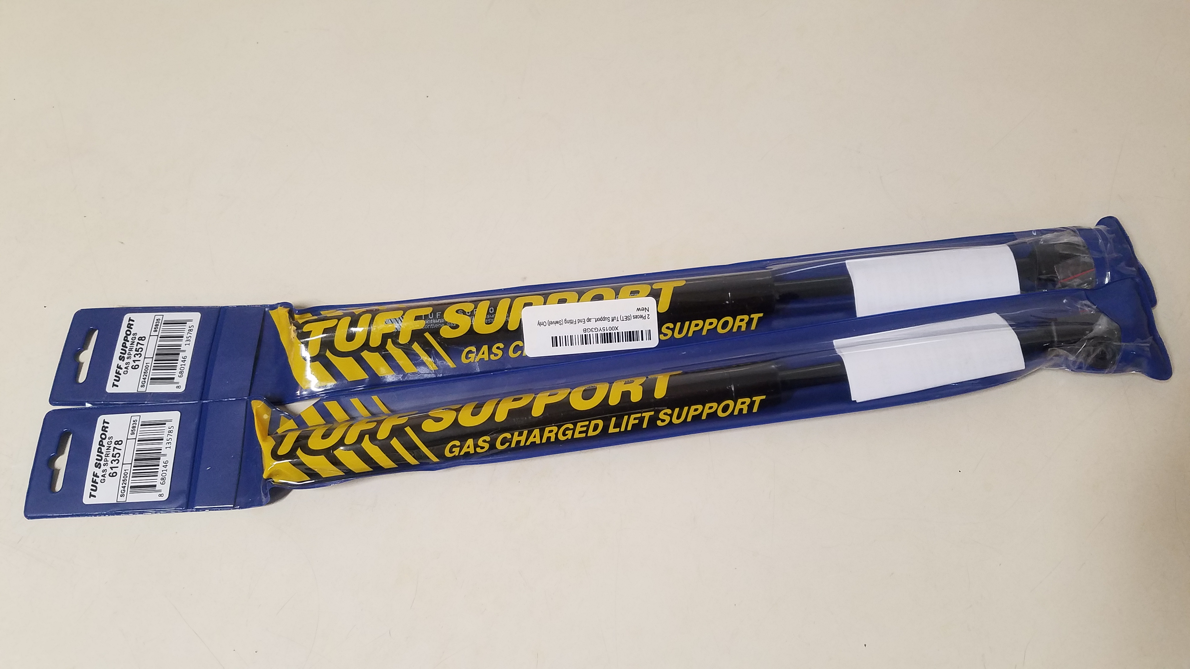
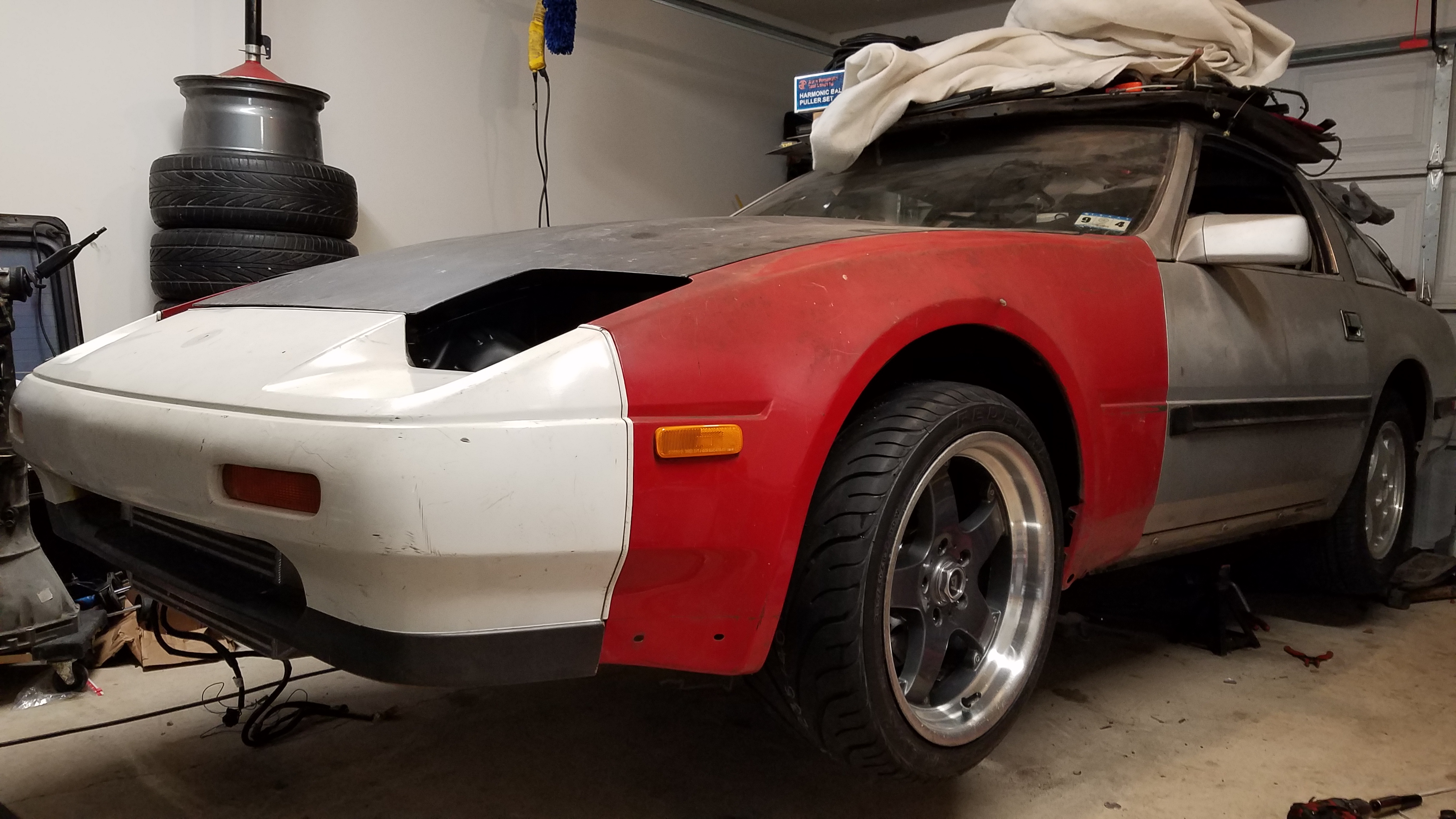
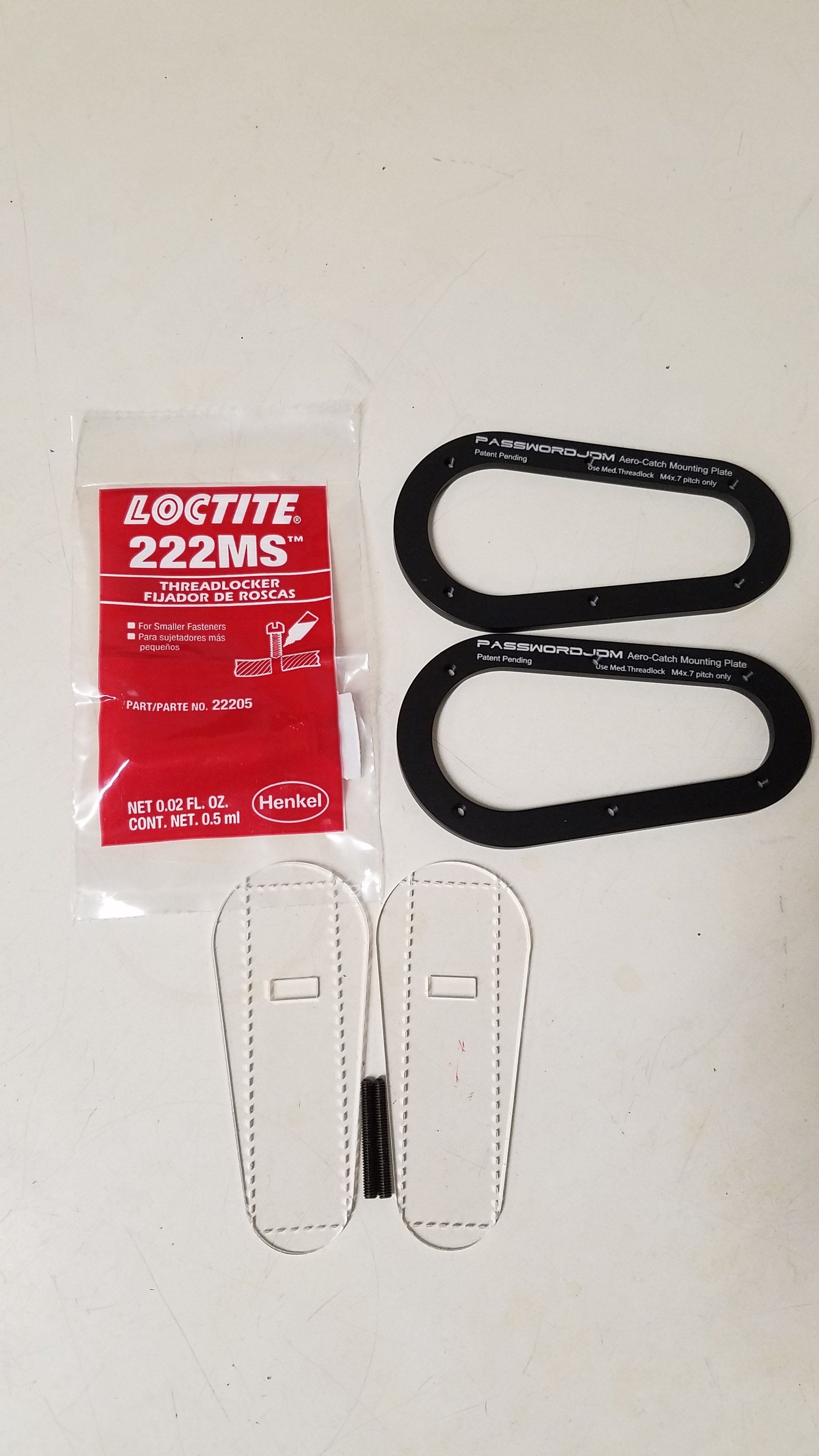
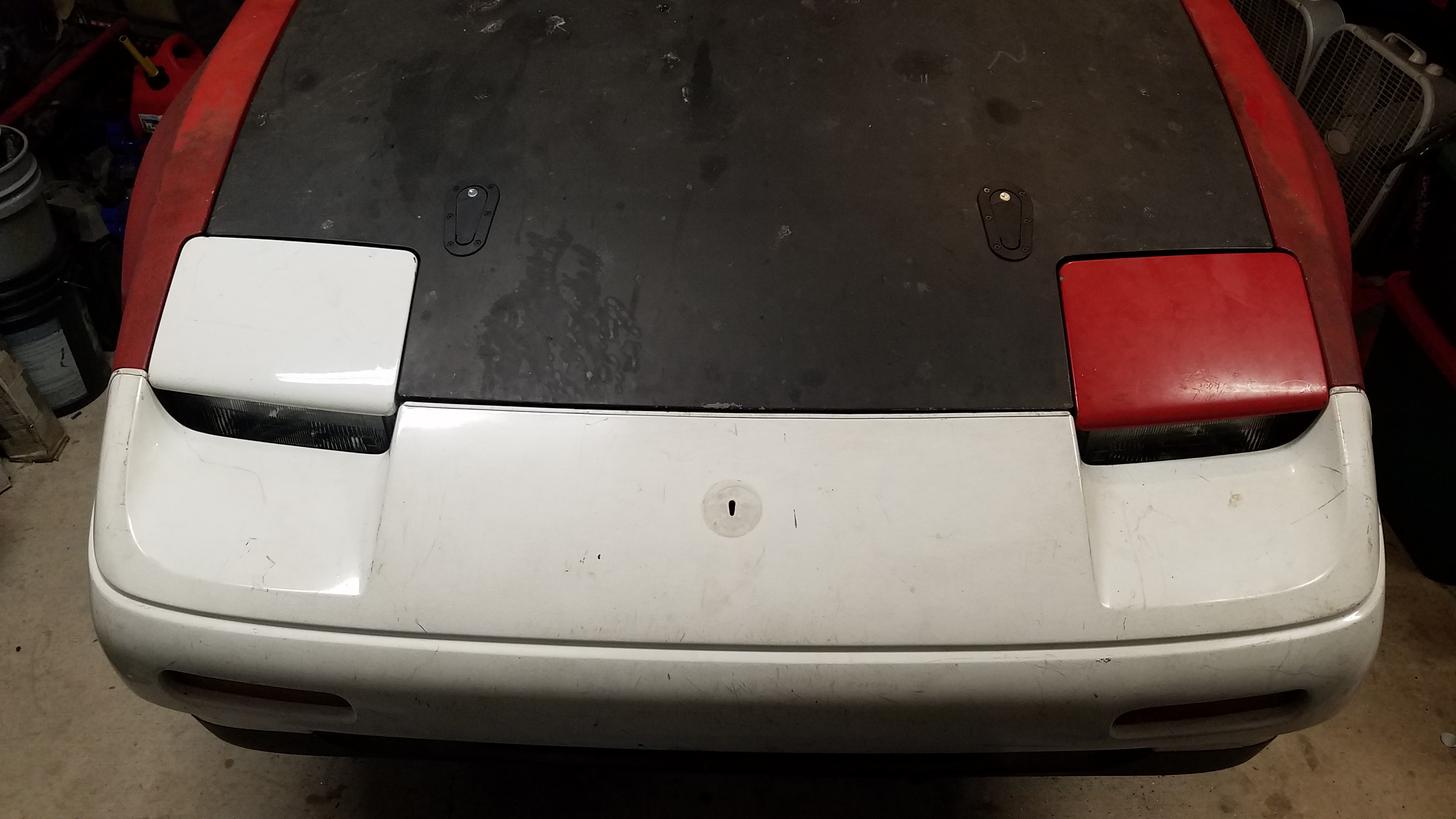
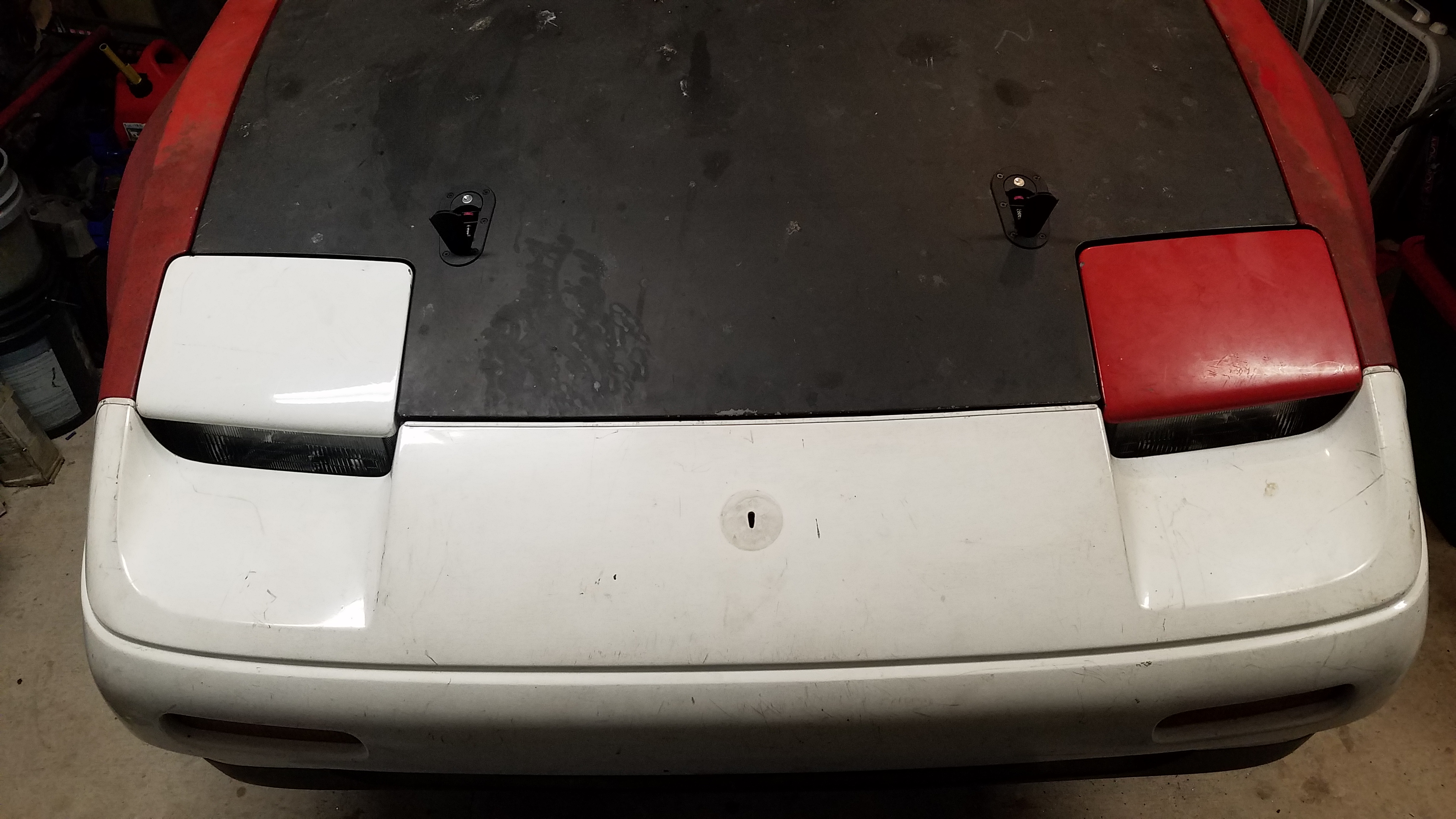
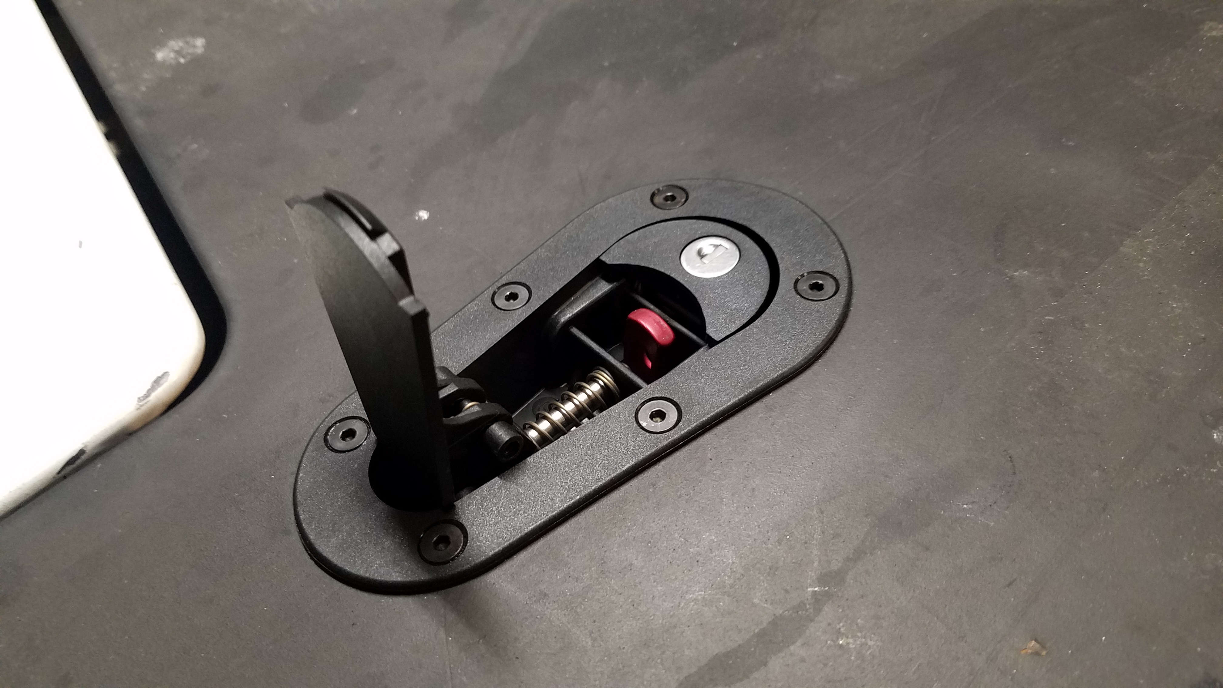
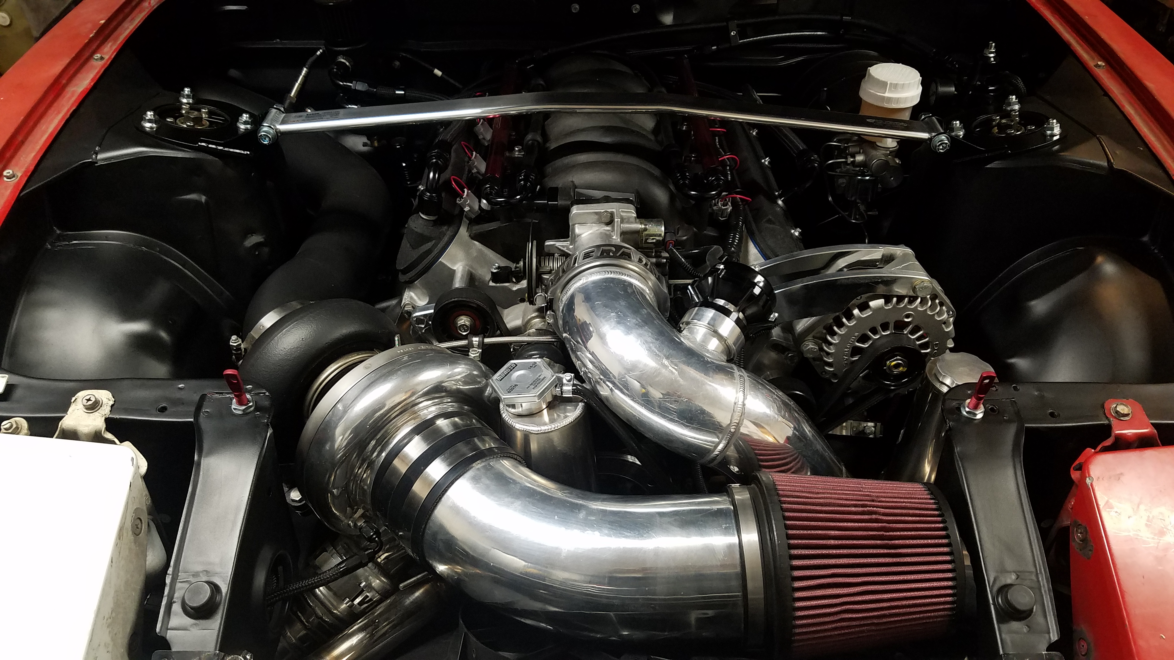
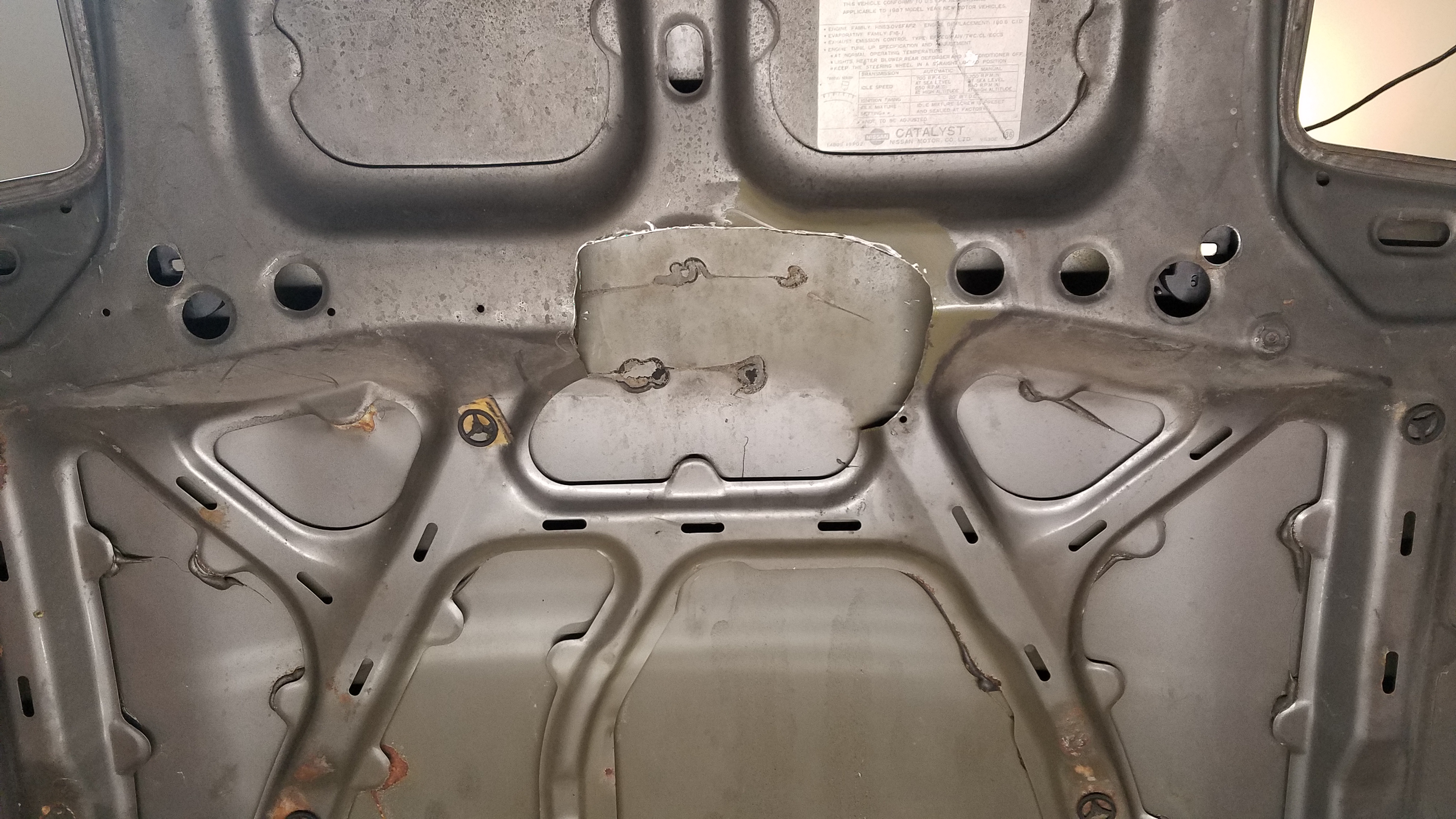
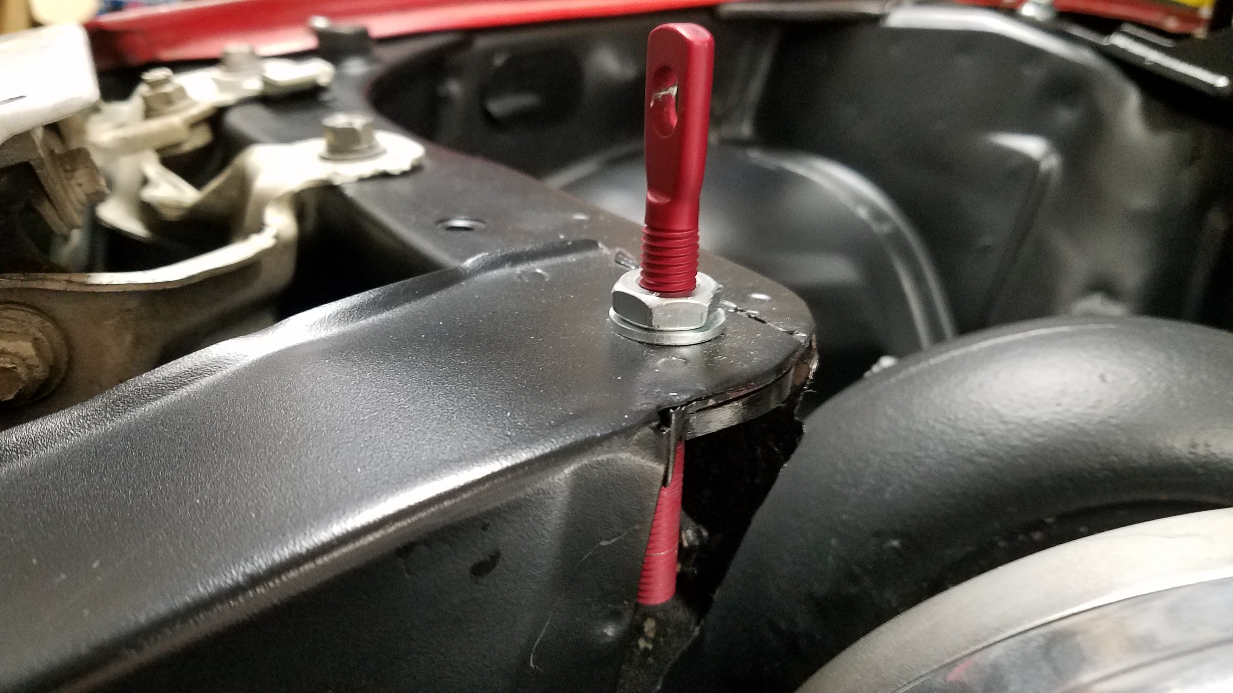
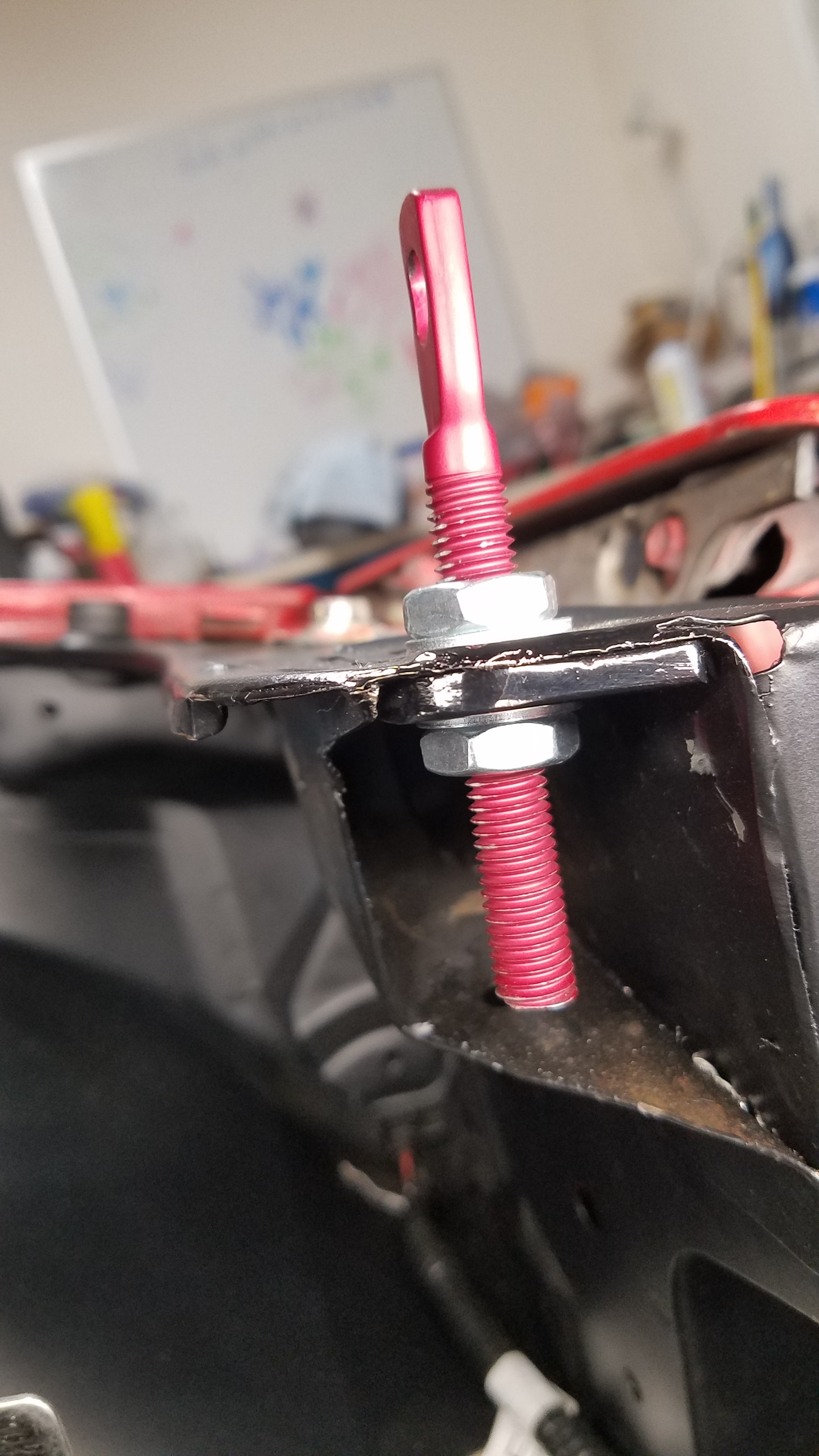
I finally gathered all the parts to finish my 87-89 front end conversion. This had literally taken me until now to get all the components required to do so. Every part expect the 2 fenders are from different cars. There was some slight modifications needed to accommodate the later style headlight buckets. The hood required modification as well. The factory hood latch was removed to clear my charge pipe. Then locking Aerocatch latches were installed to secure the hood. (Part # 120-2100 ) For additional support came in the form of 1/4in plates for the pins & Password JDM billet mounting plates for the hood. With headlight bucket(s) & hood modification tackled, everything else was a bolt on affair. Sadly the most satisfying part of this front end conversion was the installion of new hood struts. Normally these are completely blown out on Z31's. Meaning you'd have to resort to keeping a stick in the car to use as a hood prop or use visegrips. Which is just a big inconvenience. As you can tell some of the photos are from different time periods of my build. I also included a video of the Aerocatch latches in action. https://youtu.be/_eYdj38SrHk
-
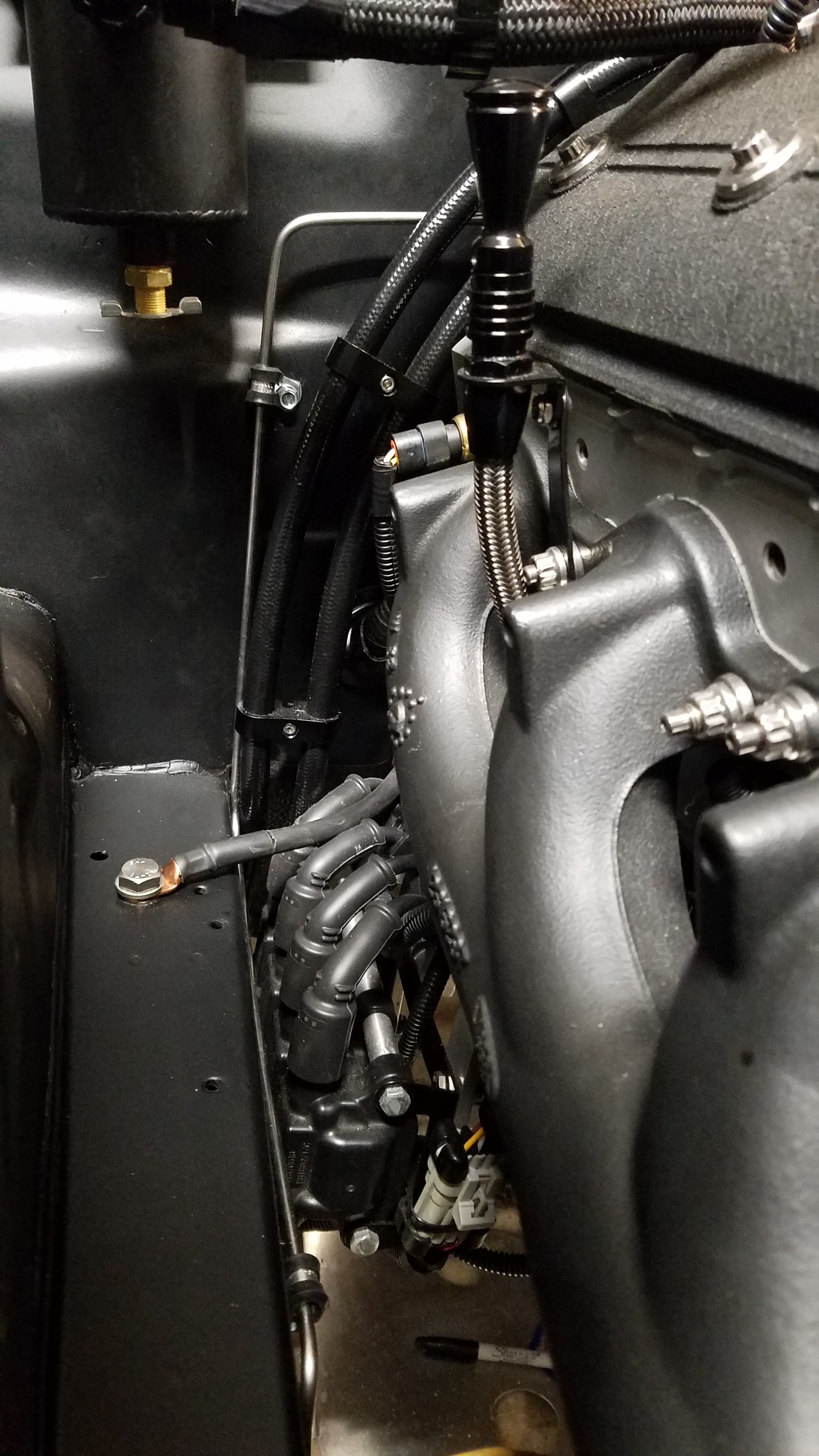
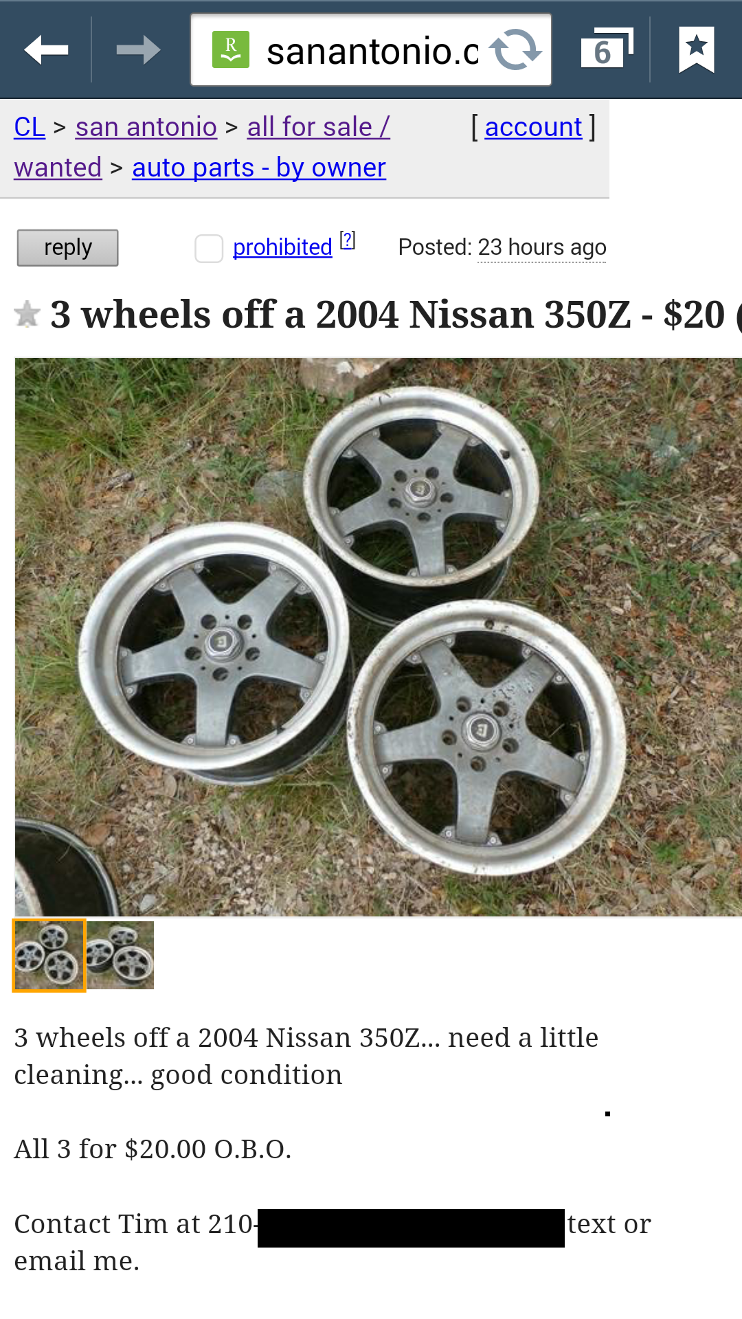
I installed Z1 Motorsports' short shifter paired with the Z Speed Solid Shifter bracket. The carbon shift knob is from my previous build from years ago. Next I got a few quotes locally to make my driveshaft & was given some pretty steep numbers. Even with reusing my a driveshaft yoke & flange. So I made a call to Shaftmasters to explain my needs. They emailed me measurement forms to fill out while I was on the phone. He literally began to make my shaft right after our conversion. It was actually shipped within 3hrs of my phone call. I ordered it on a Friday & received it Monday morning. With the Willwood setup in the front my stock wheels would no longer fit. The fronts would need a 17in wheel for proper clearance. Not wanting to spend a bunch of $ on what would be temporary wheels, I took my search to craiglist. Ended up scoring 3 Motegi Touge wheels for 10$. Couldn't beat that deal with a stick. The wheel specs are 17x9 with 24 offset. They're not any where near perfect condition but they'll work for me. I wrapped them with 235/40ZR17 90W Frederal 595 RS-R tires. The rear tires are just factory size Ohtsu all season tires. This wheel & tire combo aren't my long term solution. They're just meant to last through my clutch break in.
-
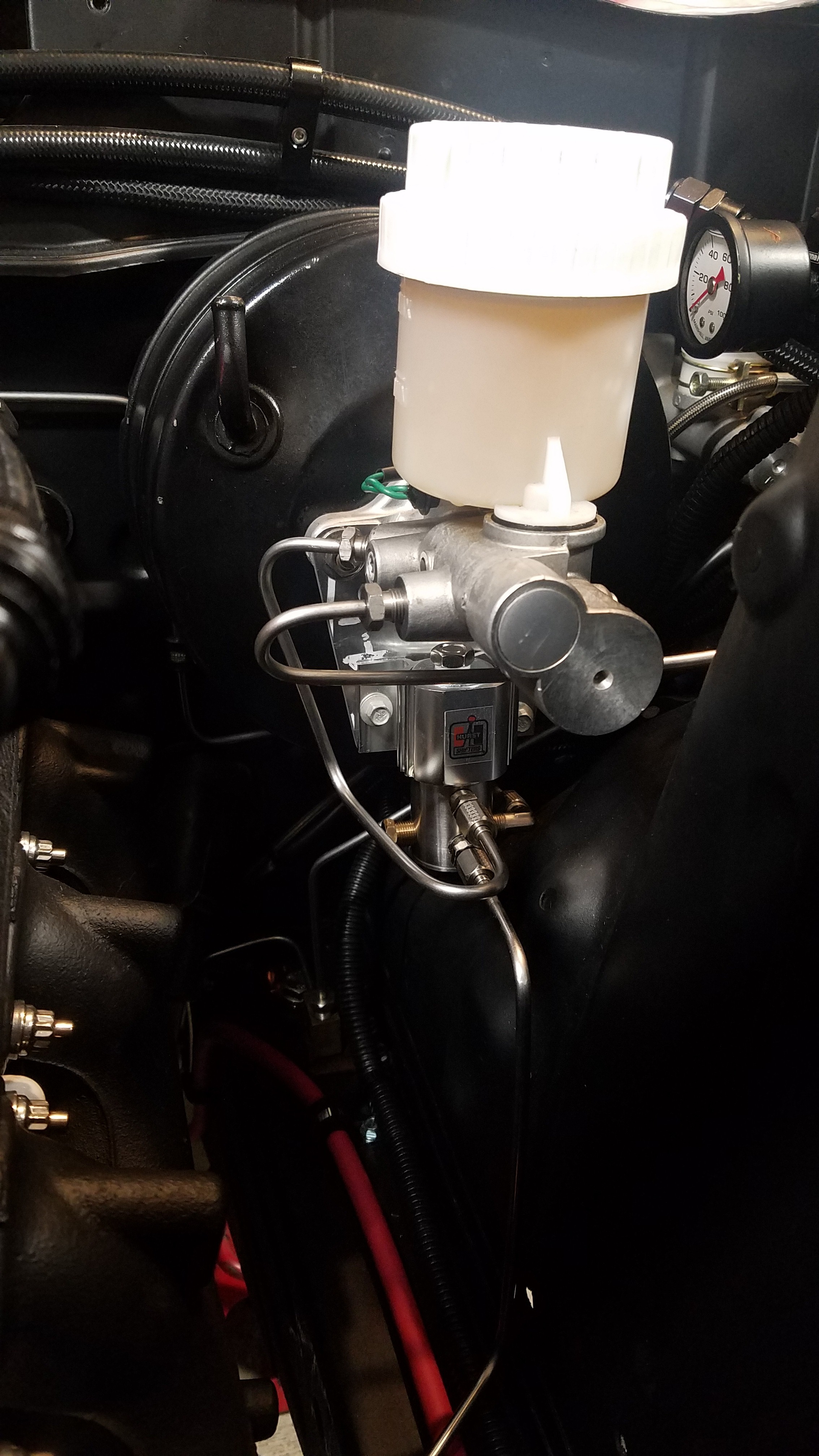
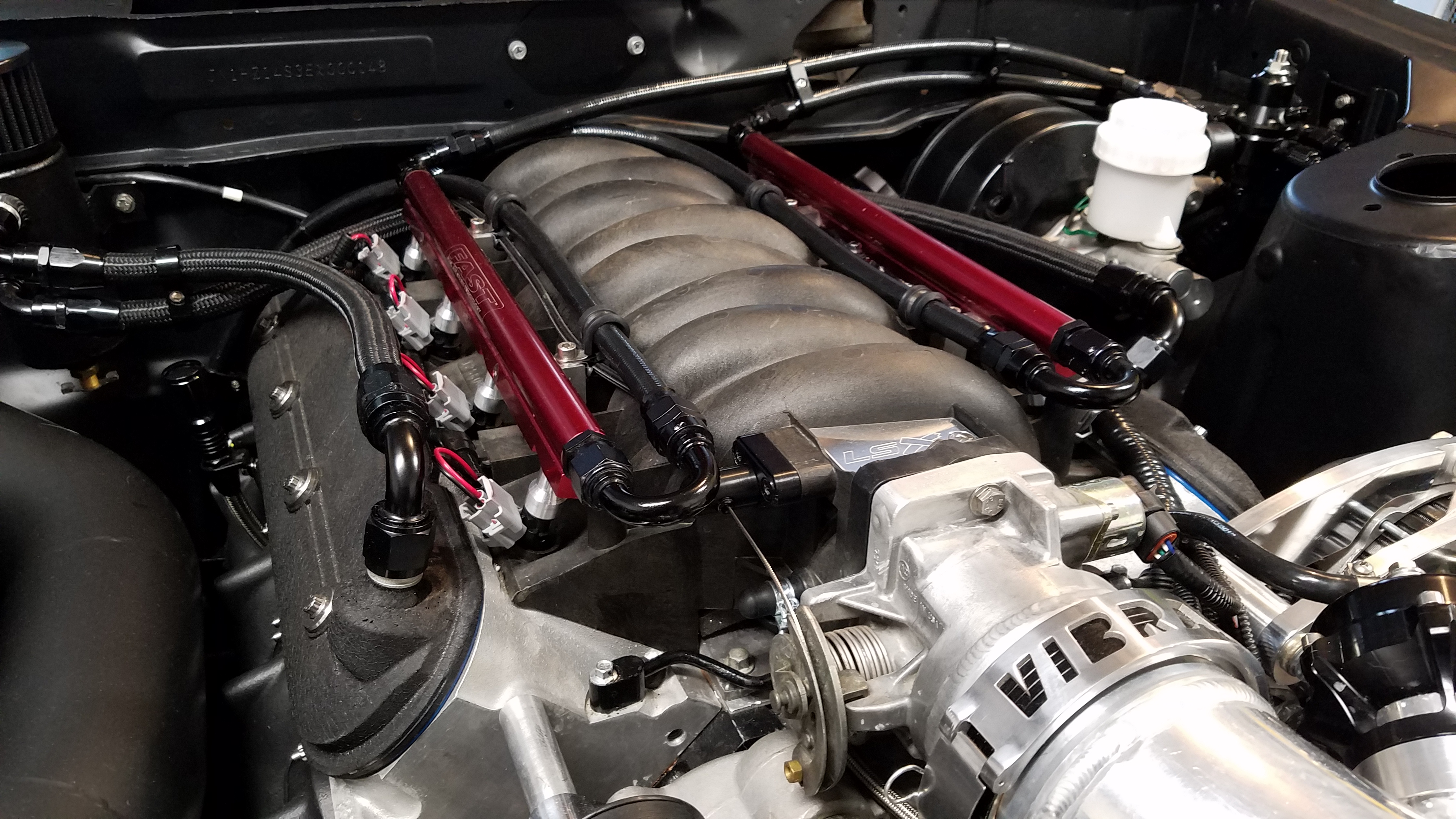
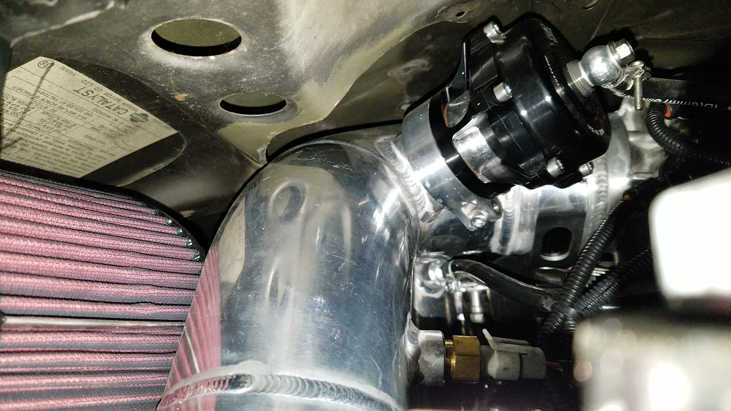
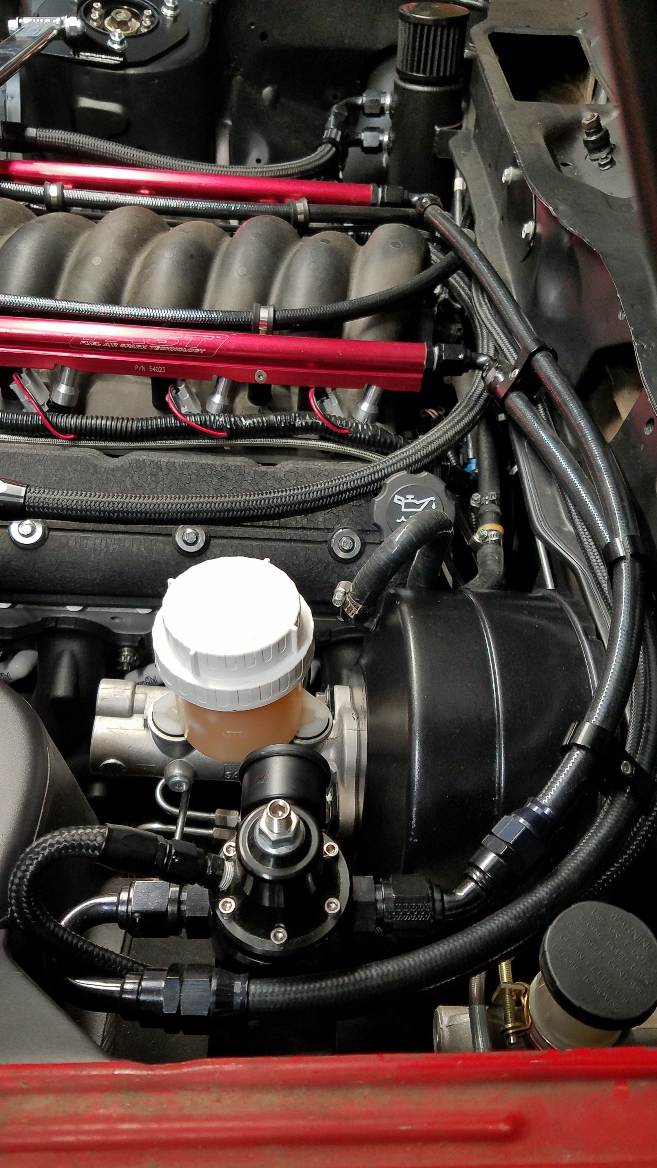
Finishing off the brake system I used a Z1 Motorsports' Z32 Silicone brake booster hose to connected to the intake manifold LS1. I also made a boost reference for my fuel pressure regulator.
-
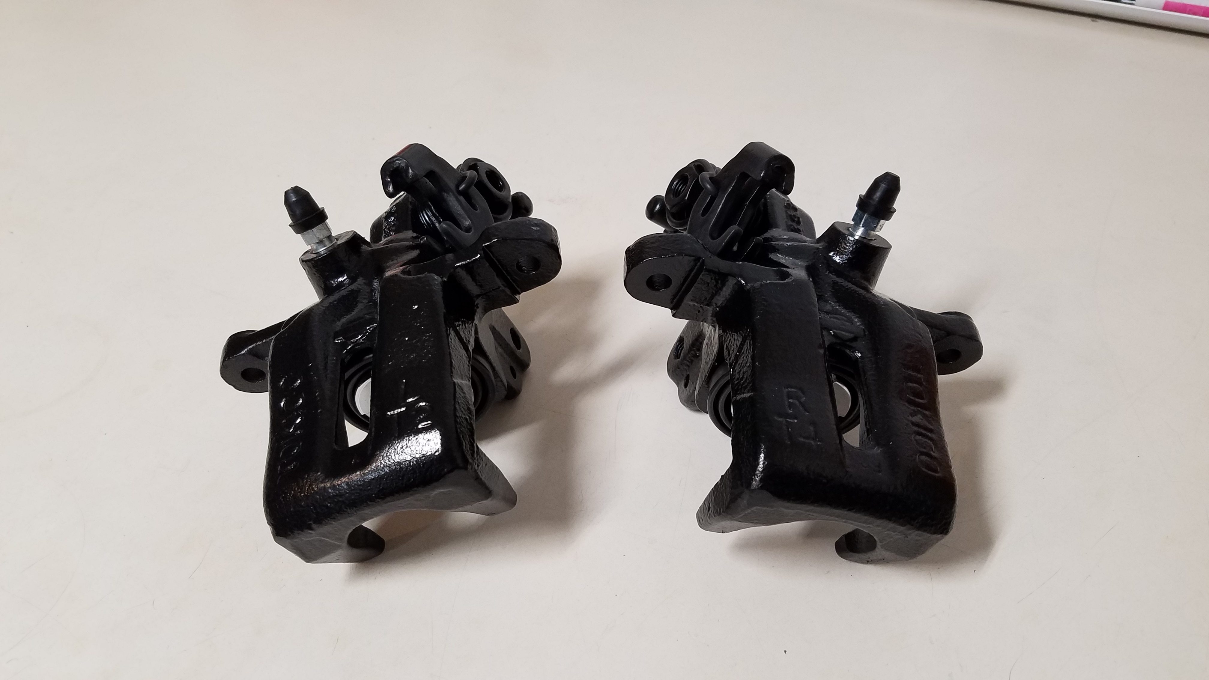
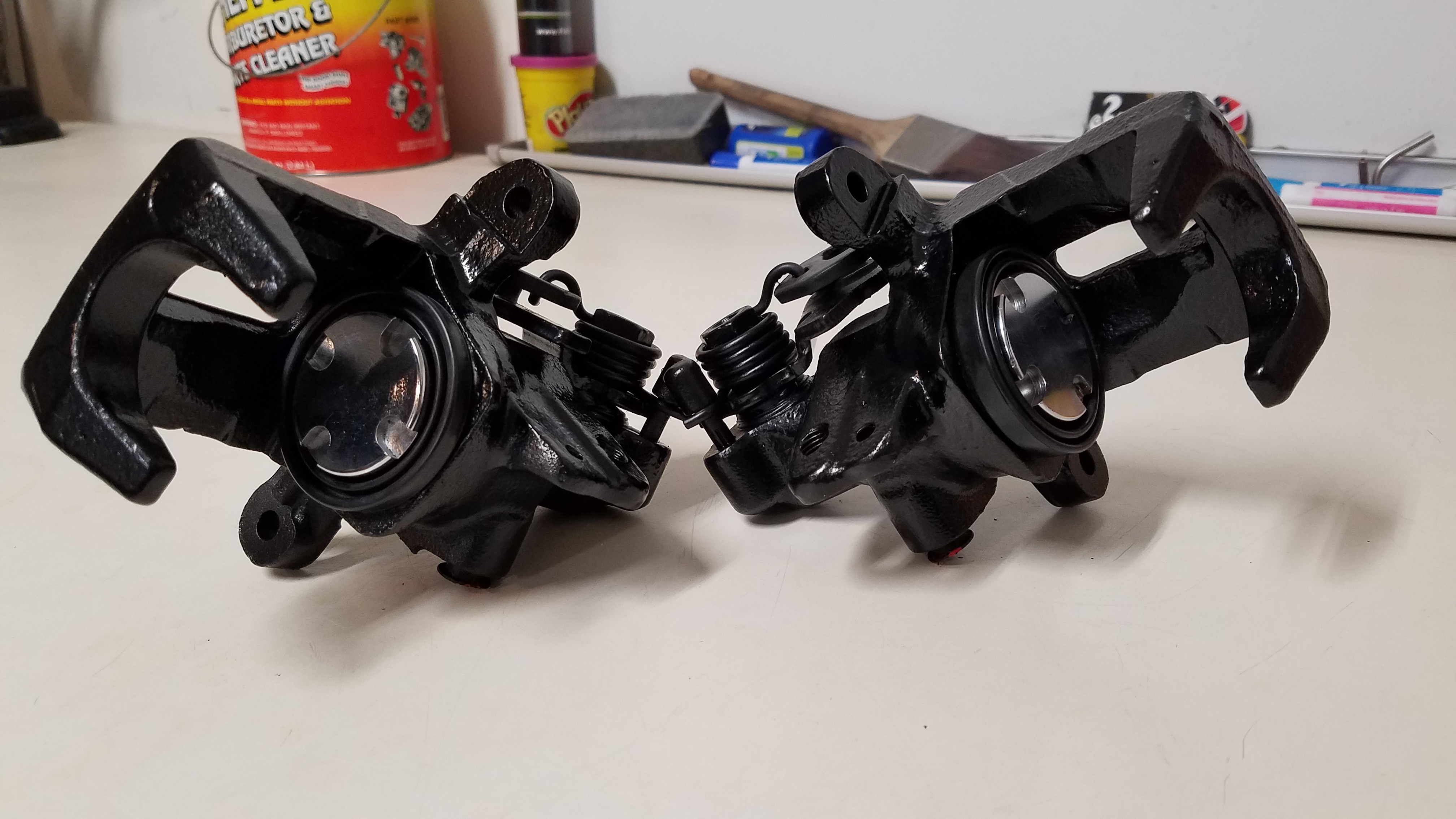
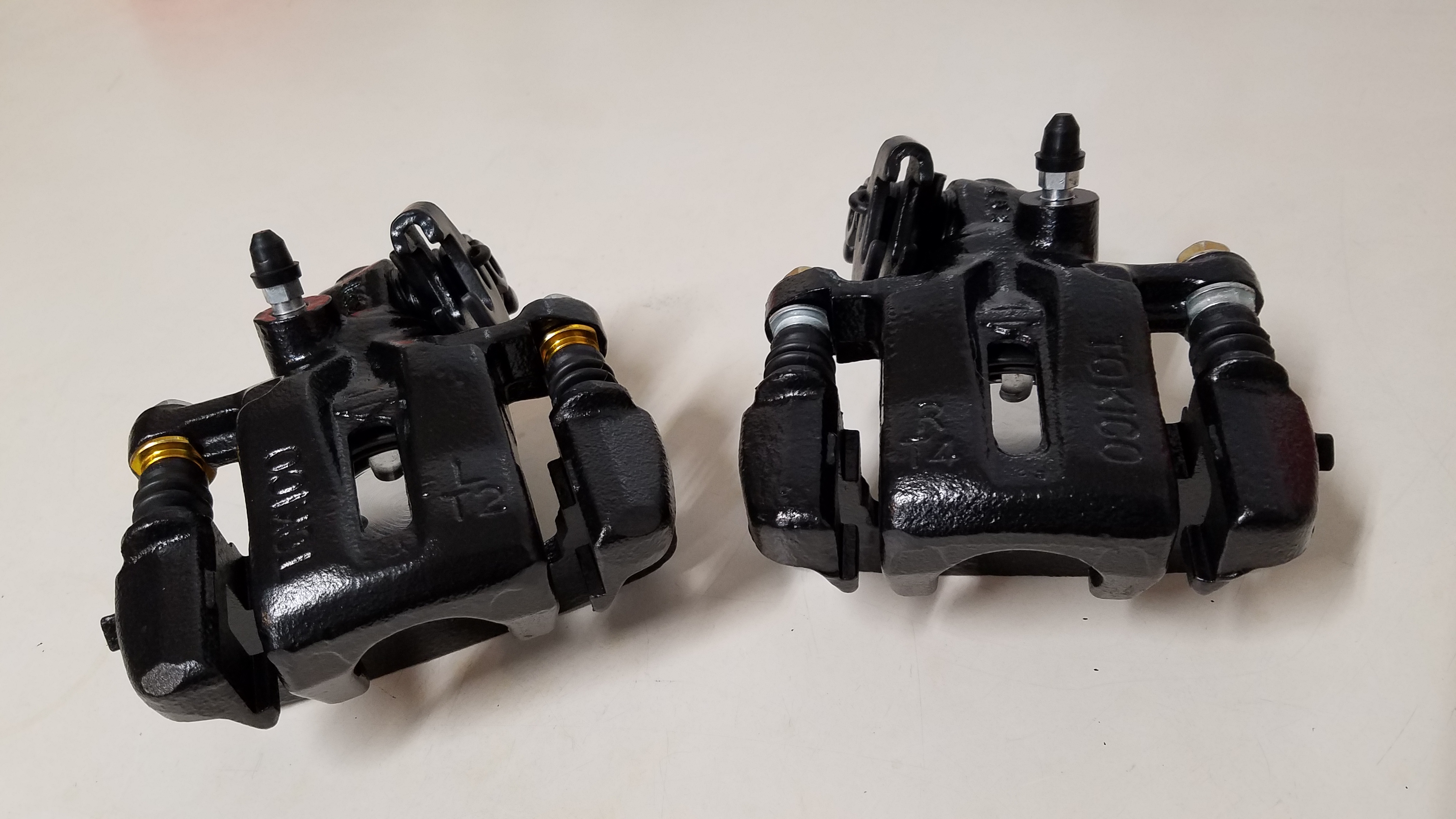
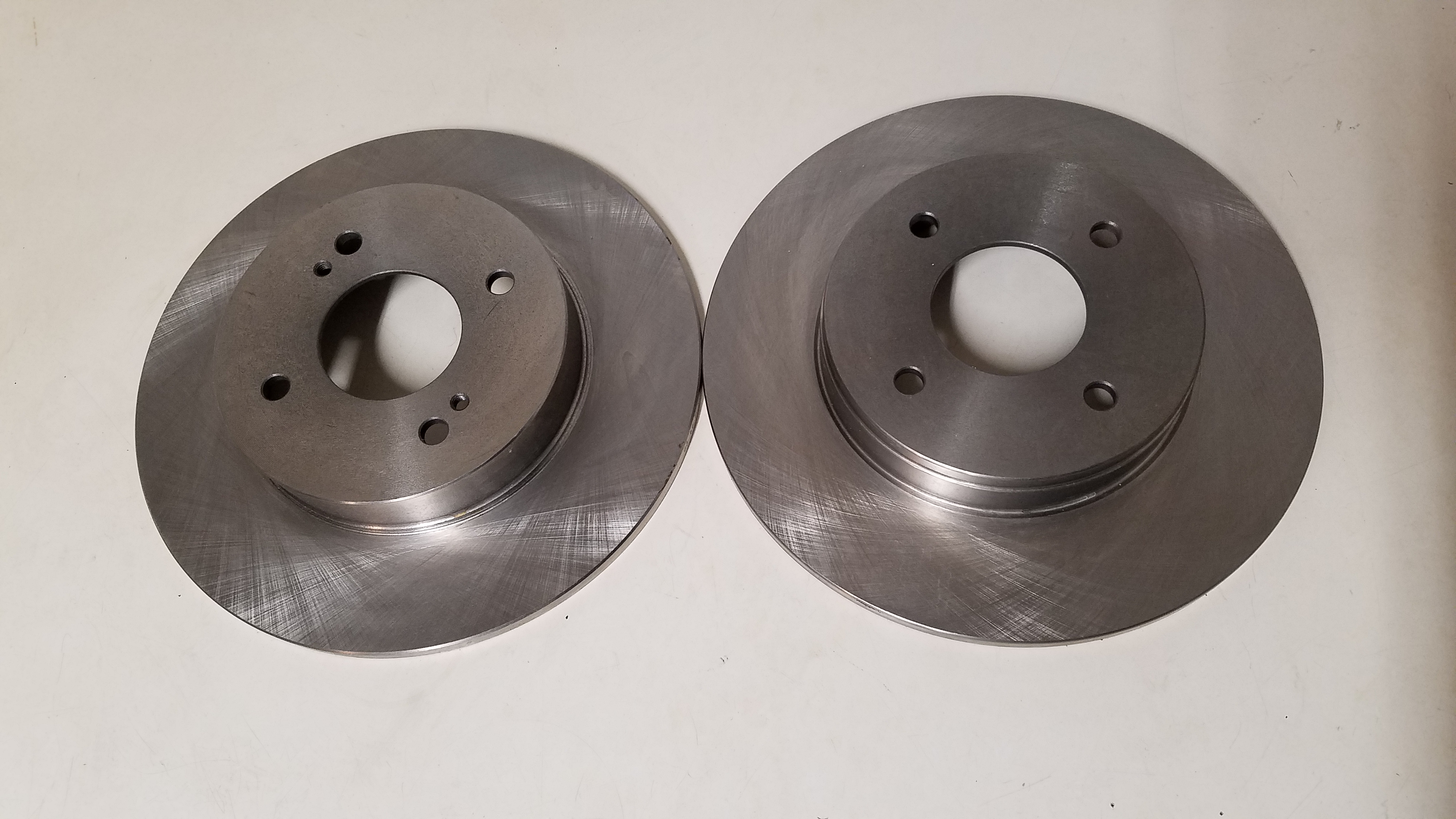
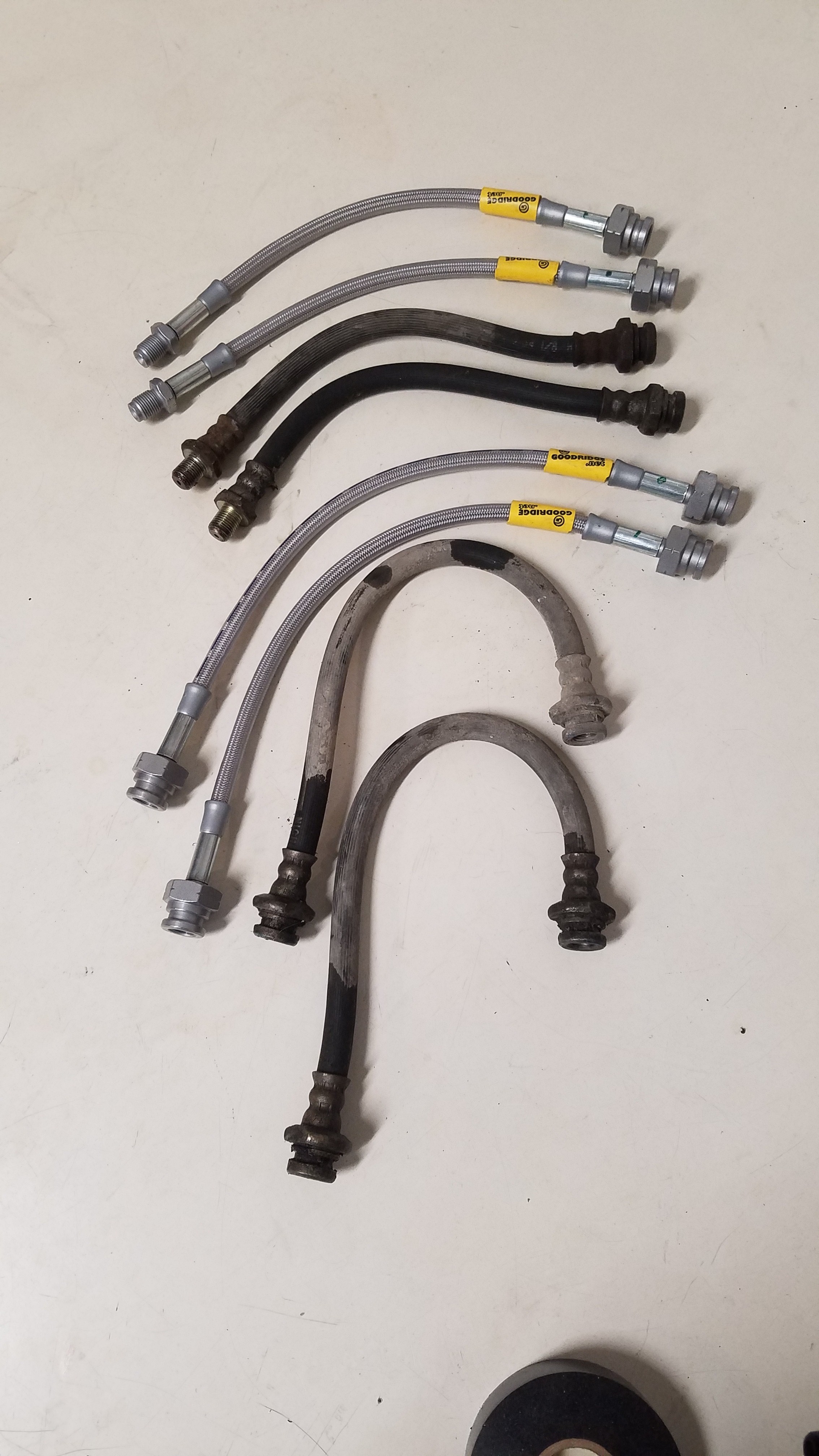
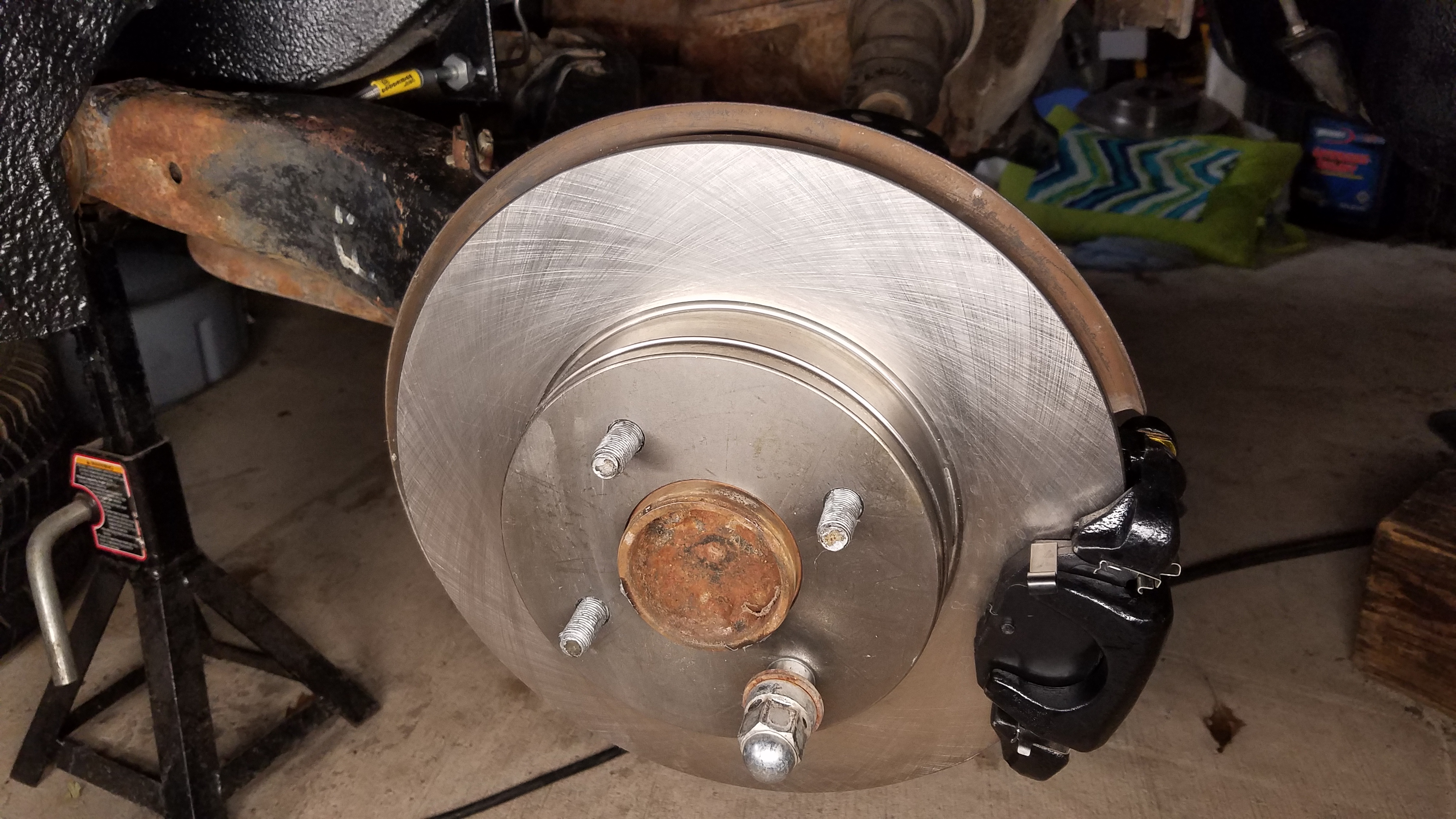
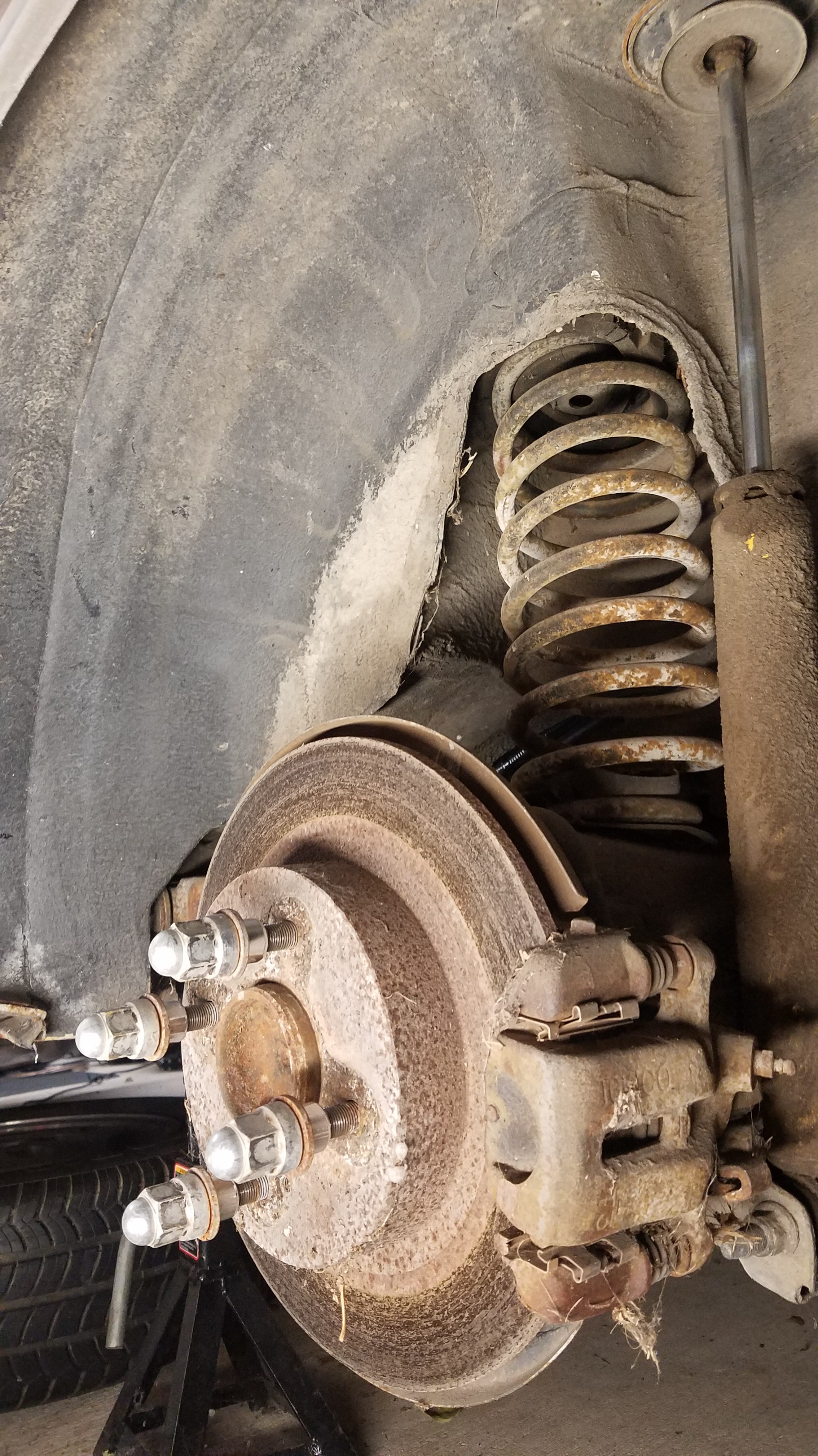
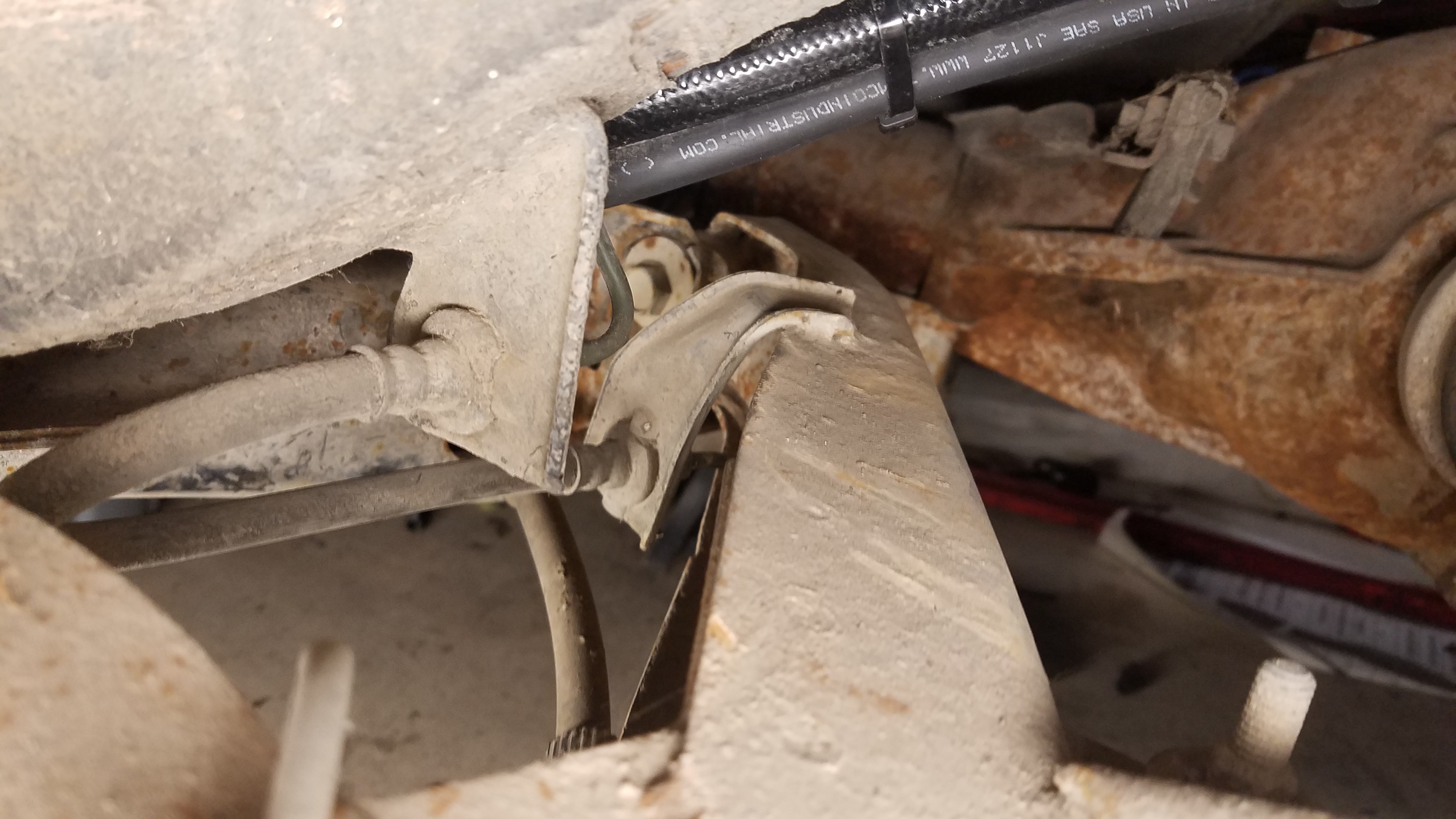
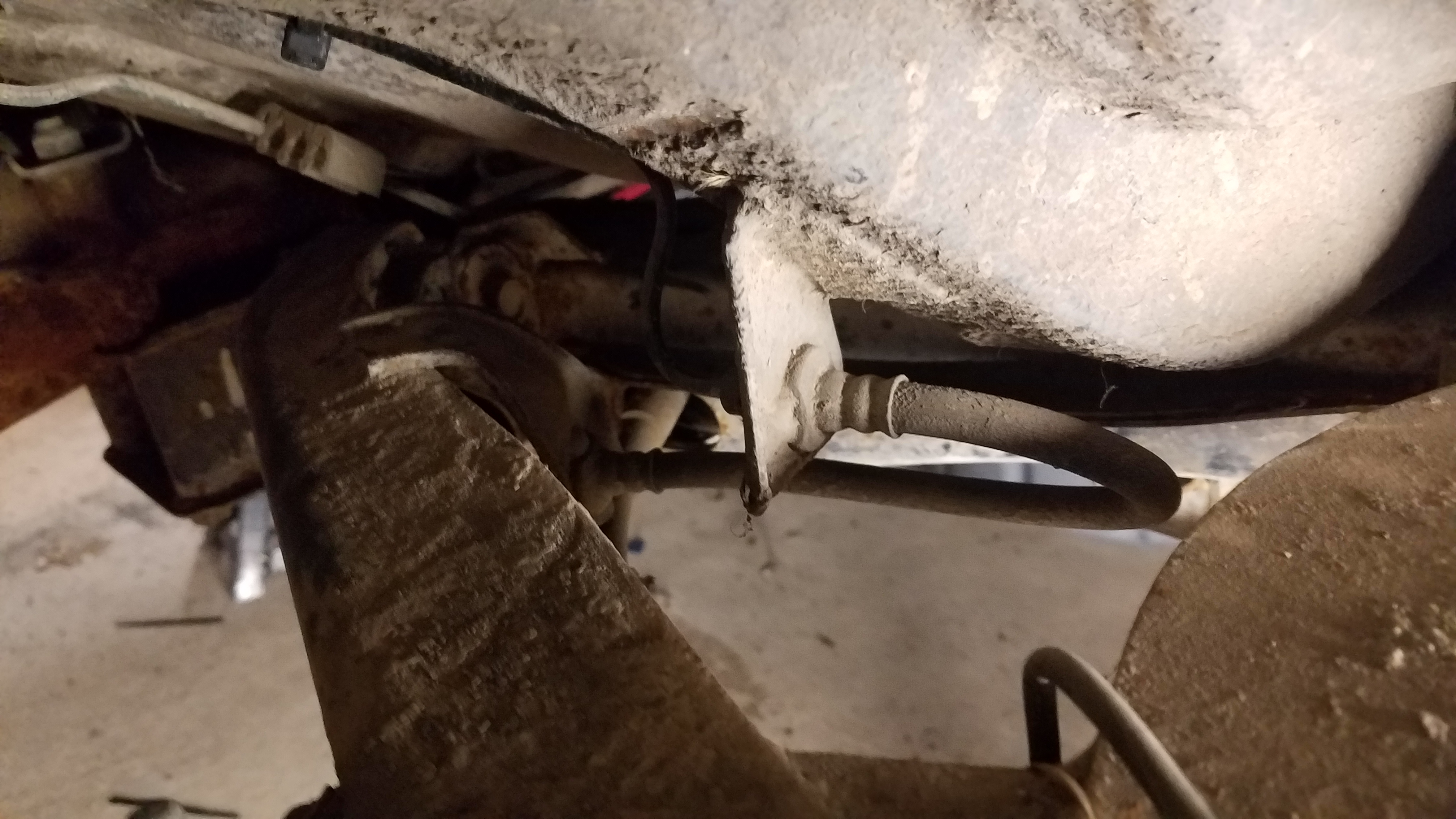
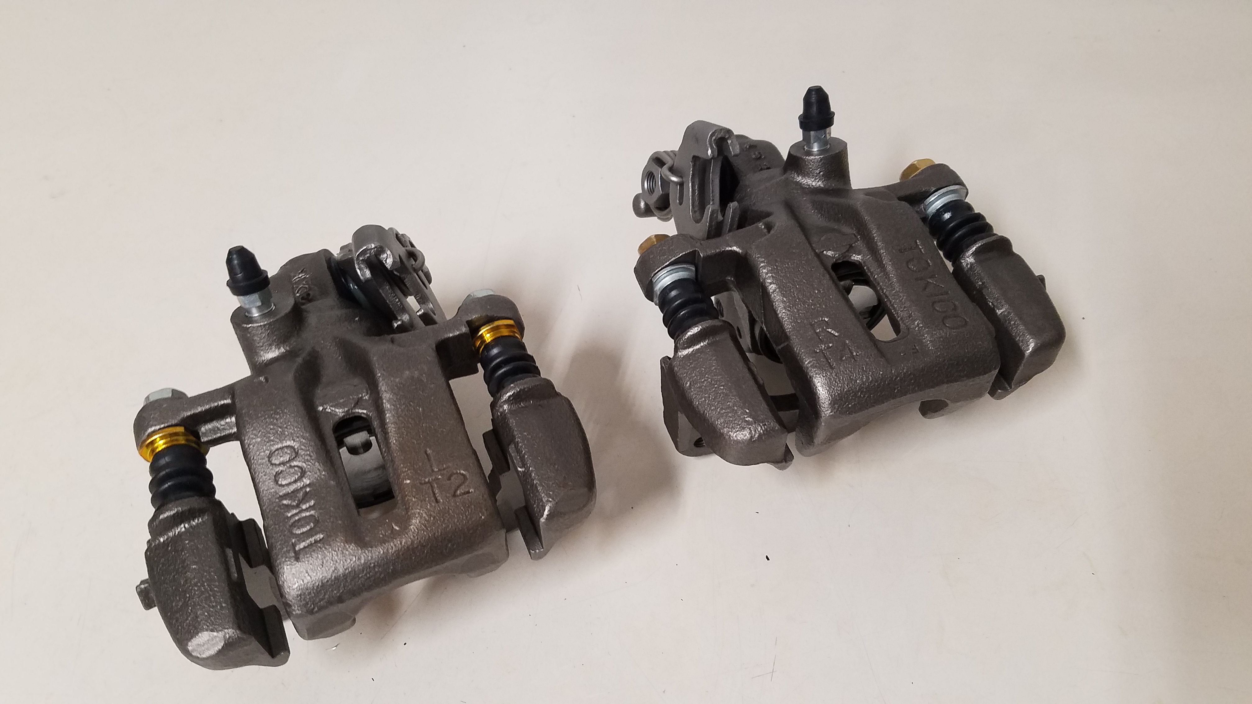
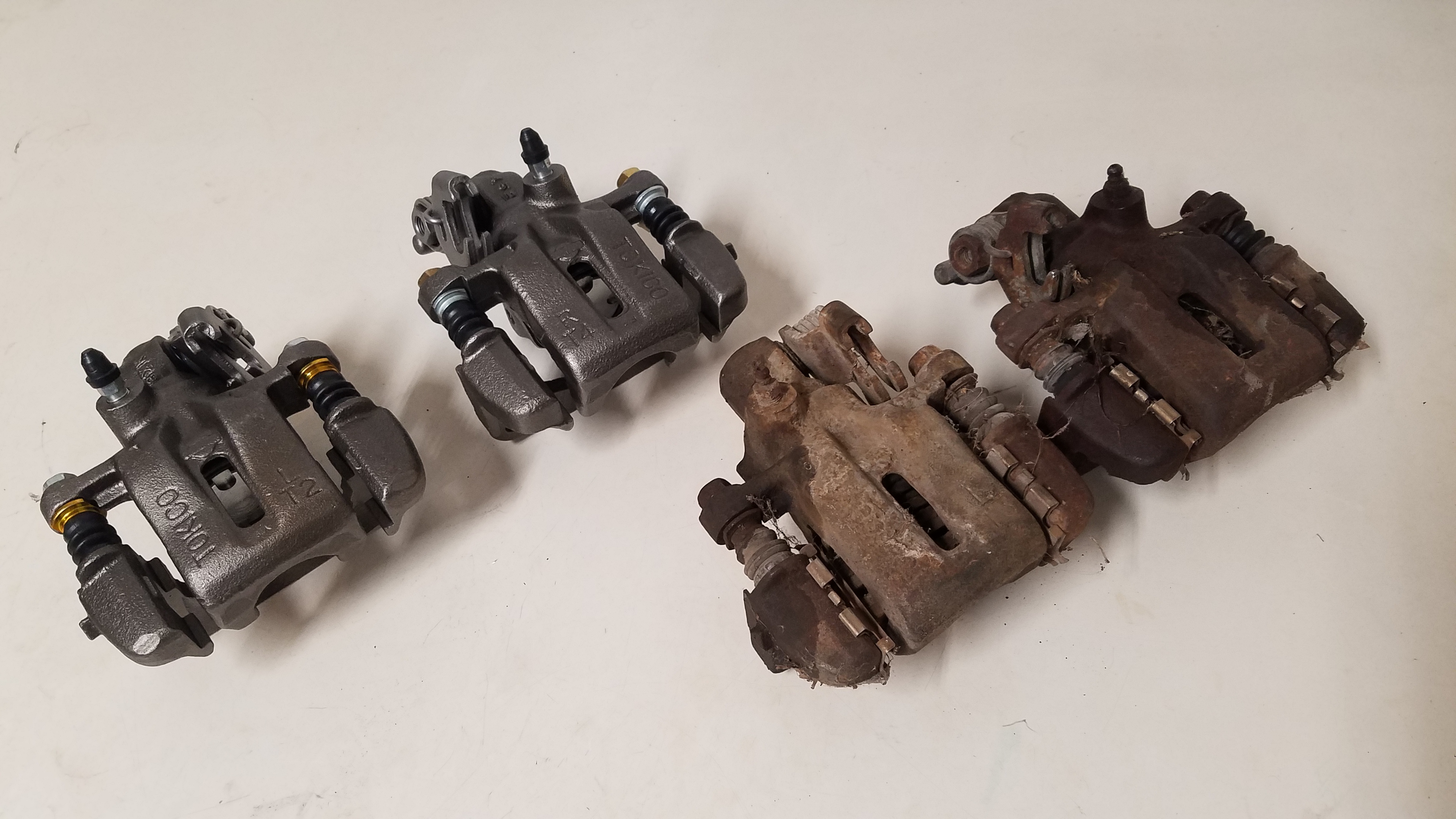
Stainless steel braided Goodridge hoses were used to replace the rear rubber hoses. For the rear brakes there's nothing too exciting going on. Just some freshly painted remanufactured calipers. Along with replacement factory pads & rotors. I was considering doing a 5 lug swap with vented rotors but decided tart would be a waste of $. Especially when I'll be swapping to the s13 subframe in the coming months. At this point I was fed up with not driving the car aka being a member of the "Jack Stand Mafia". Here's a couple photos.
-
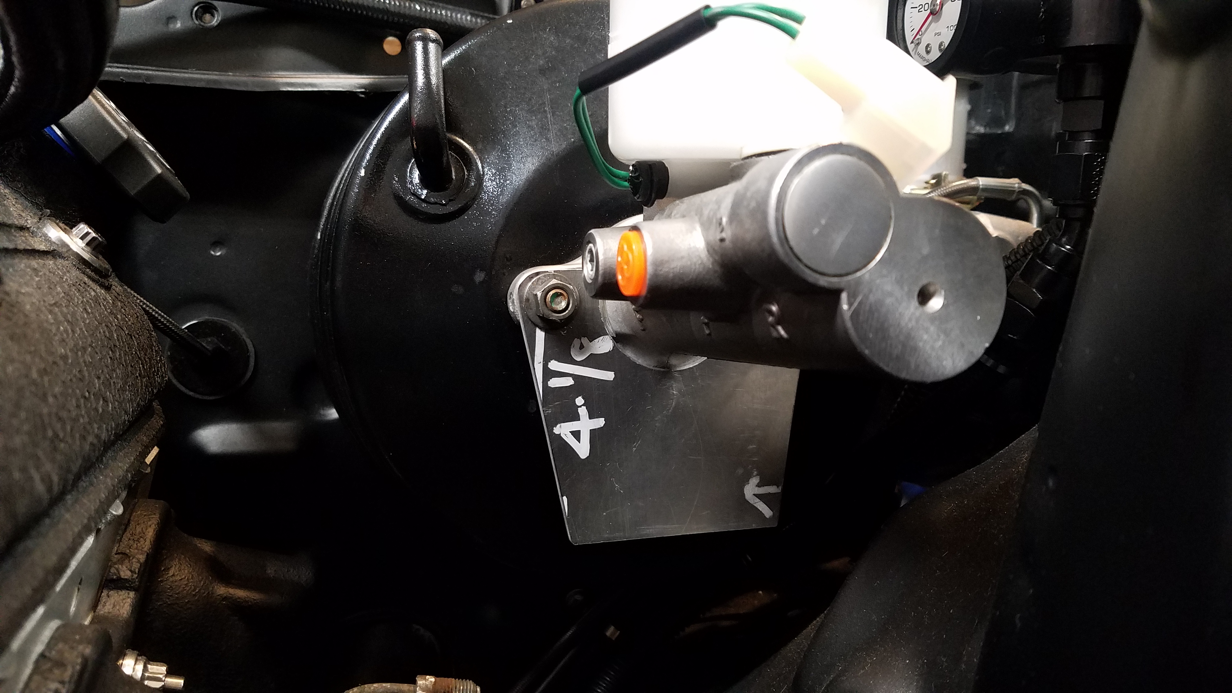
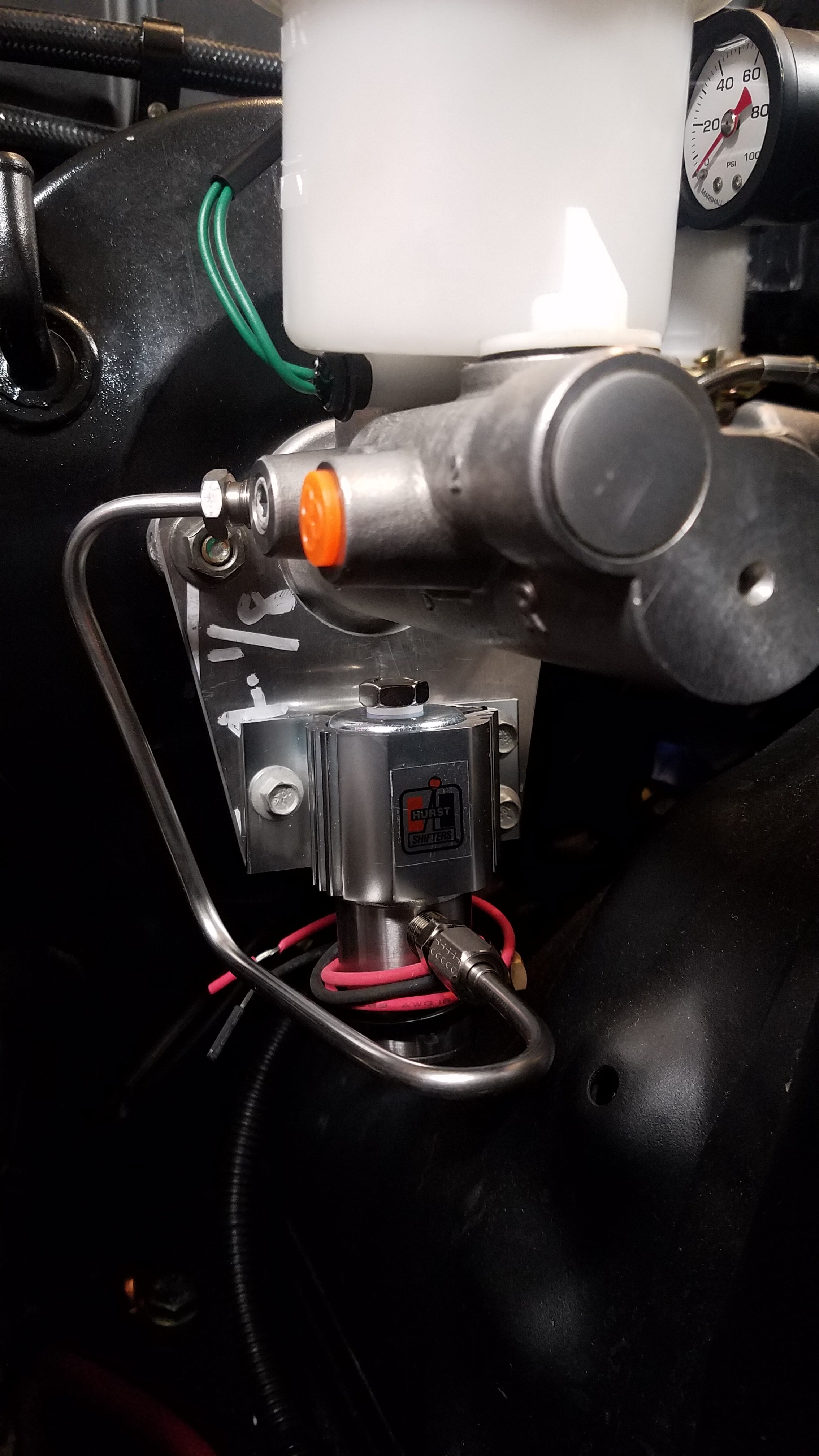
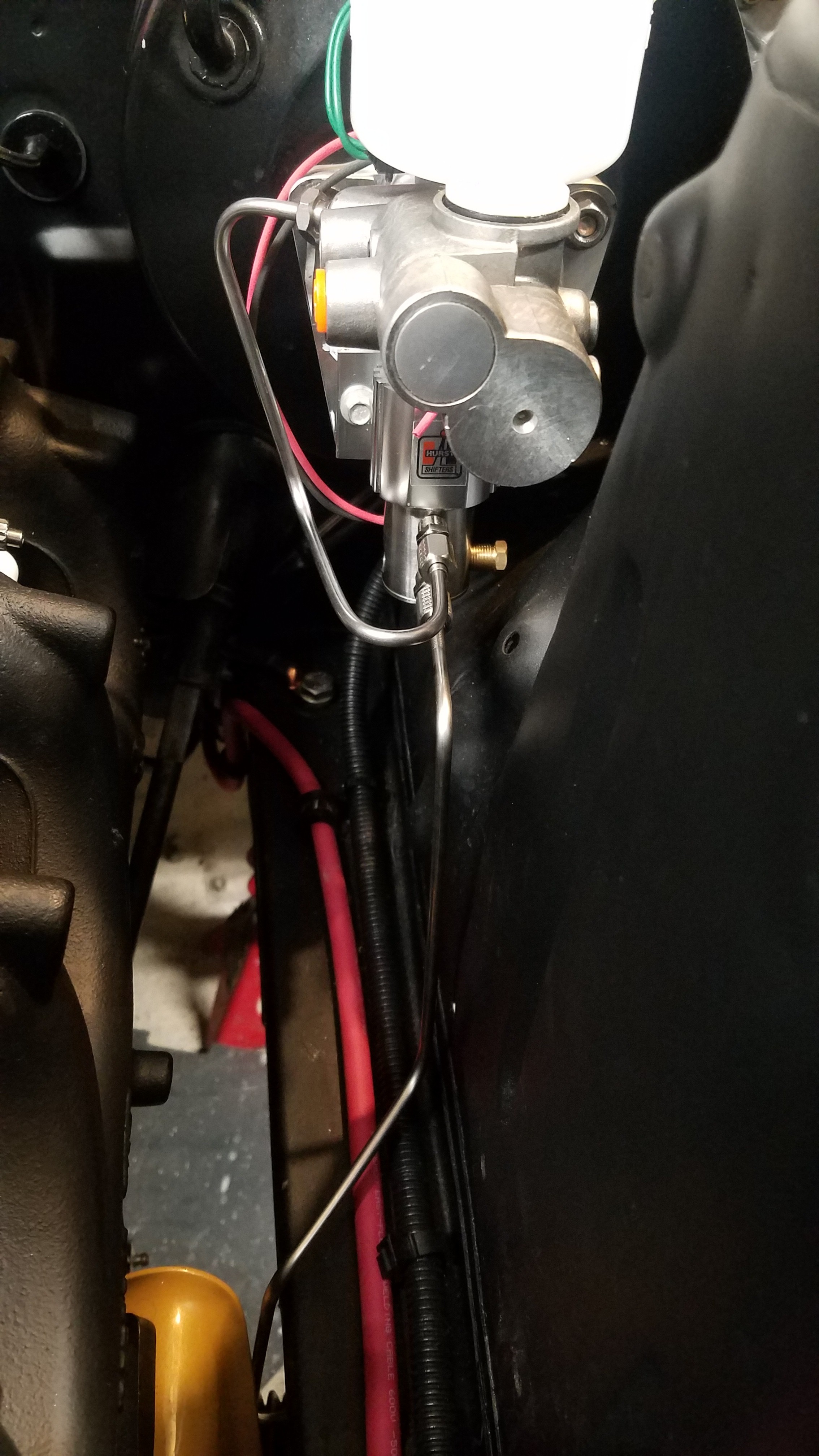
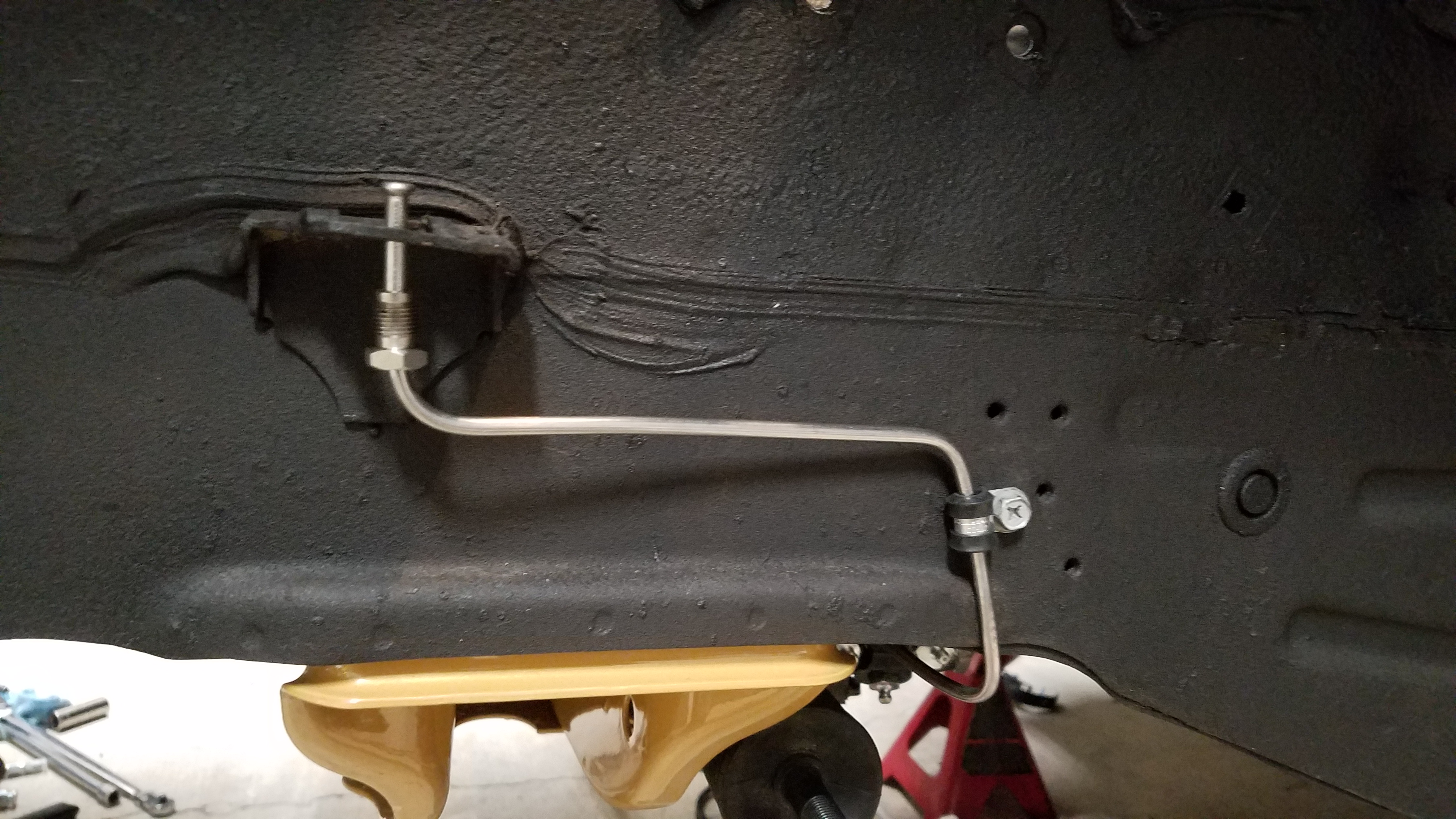
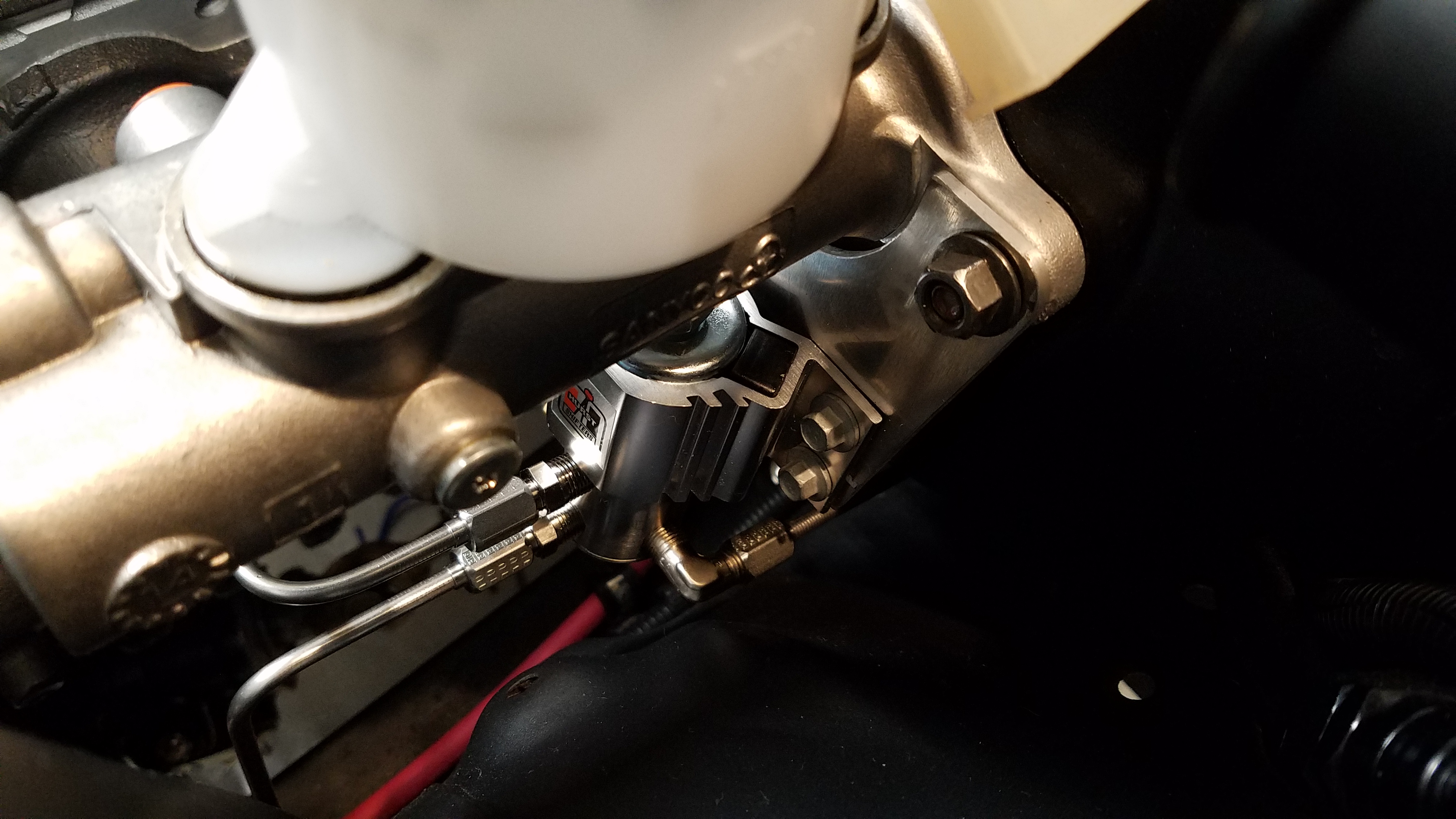
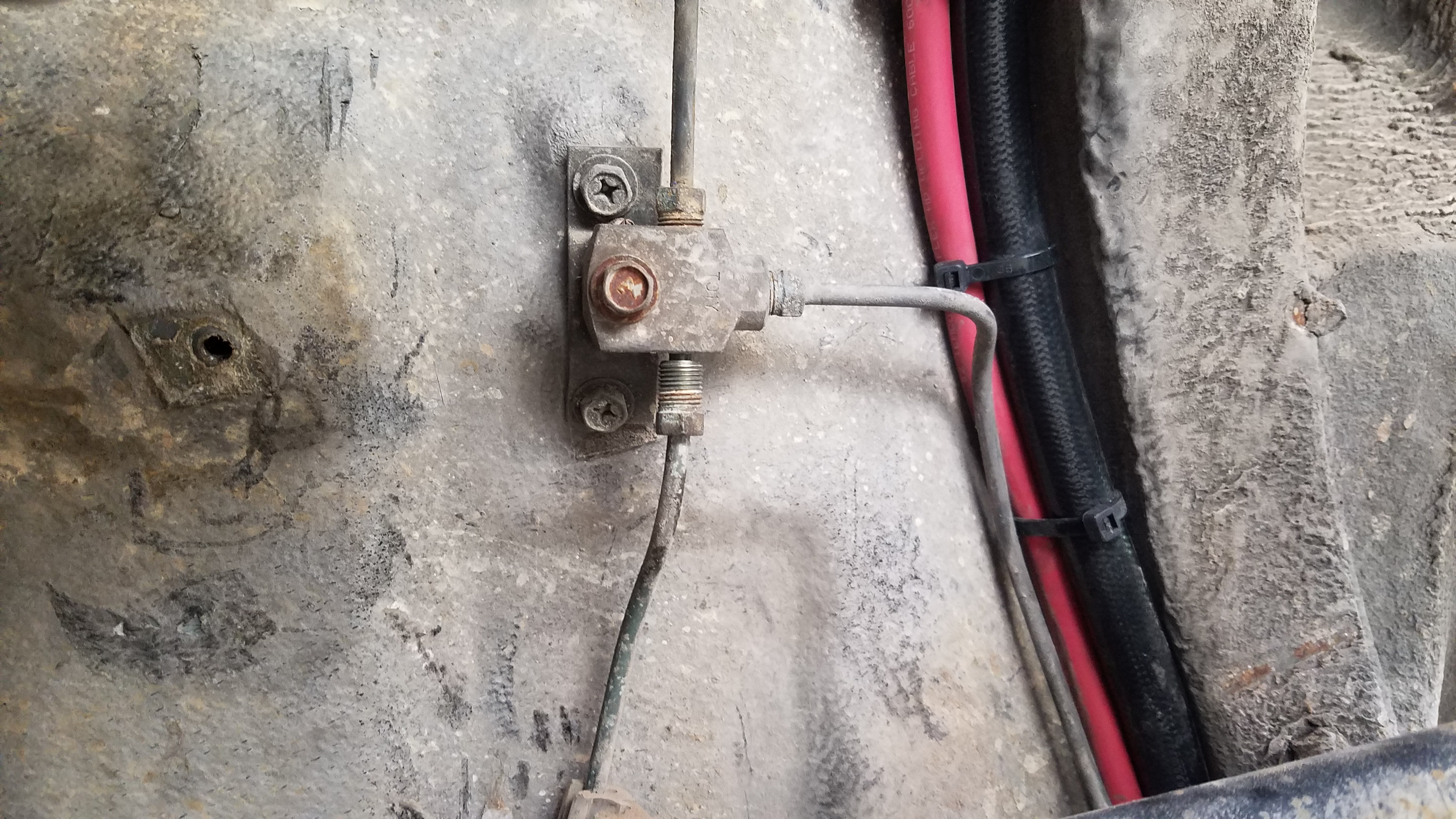
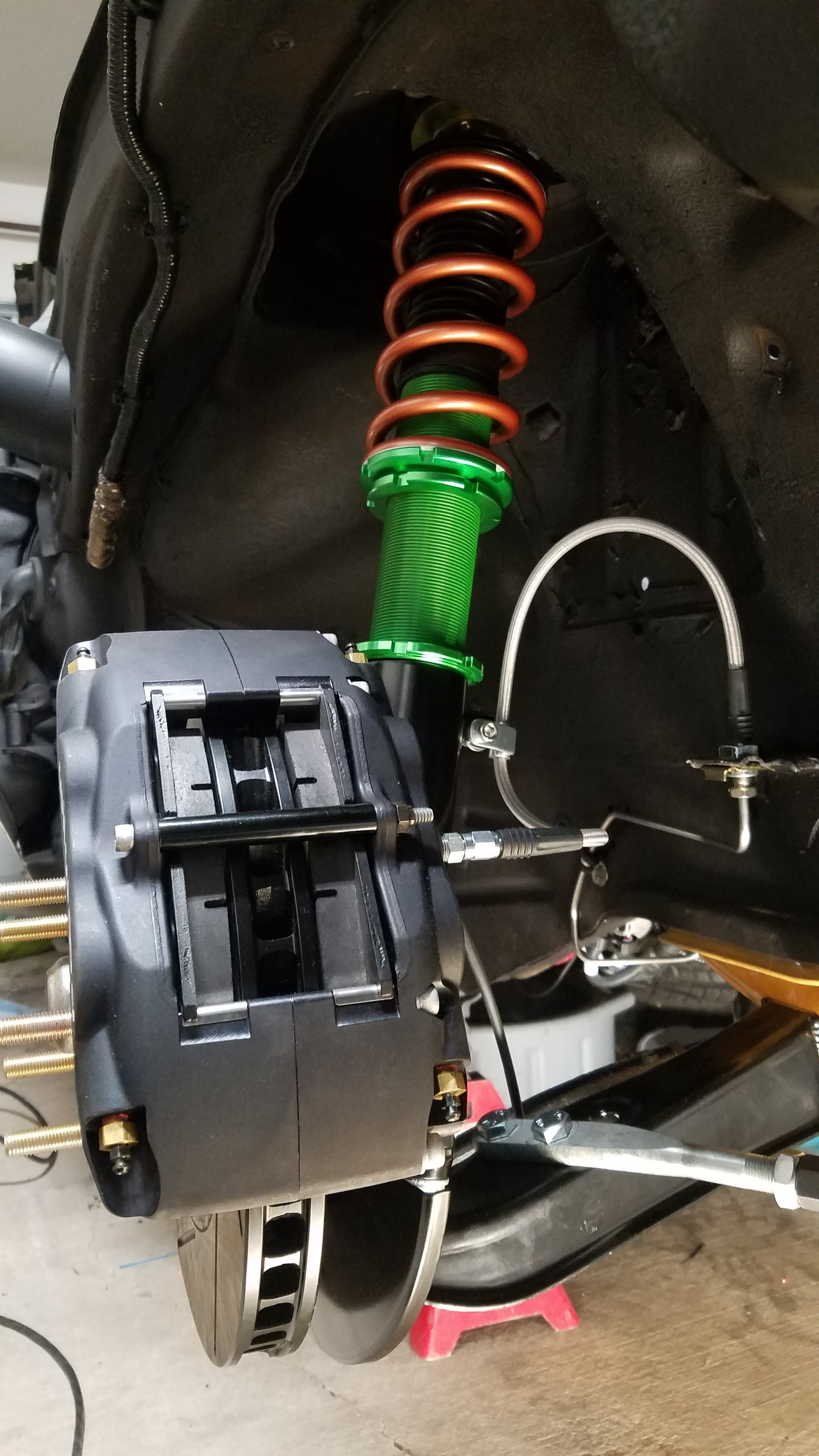
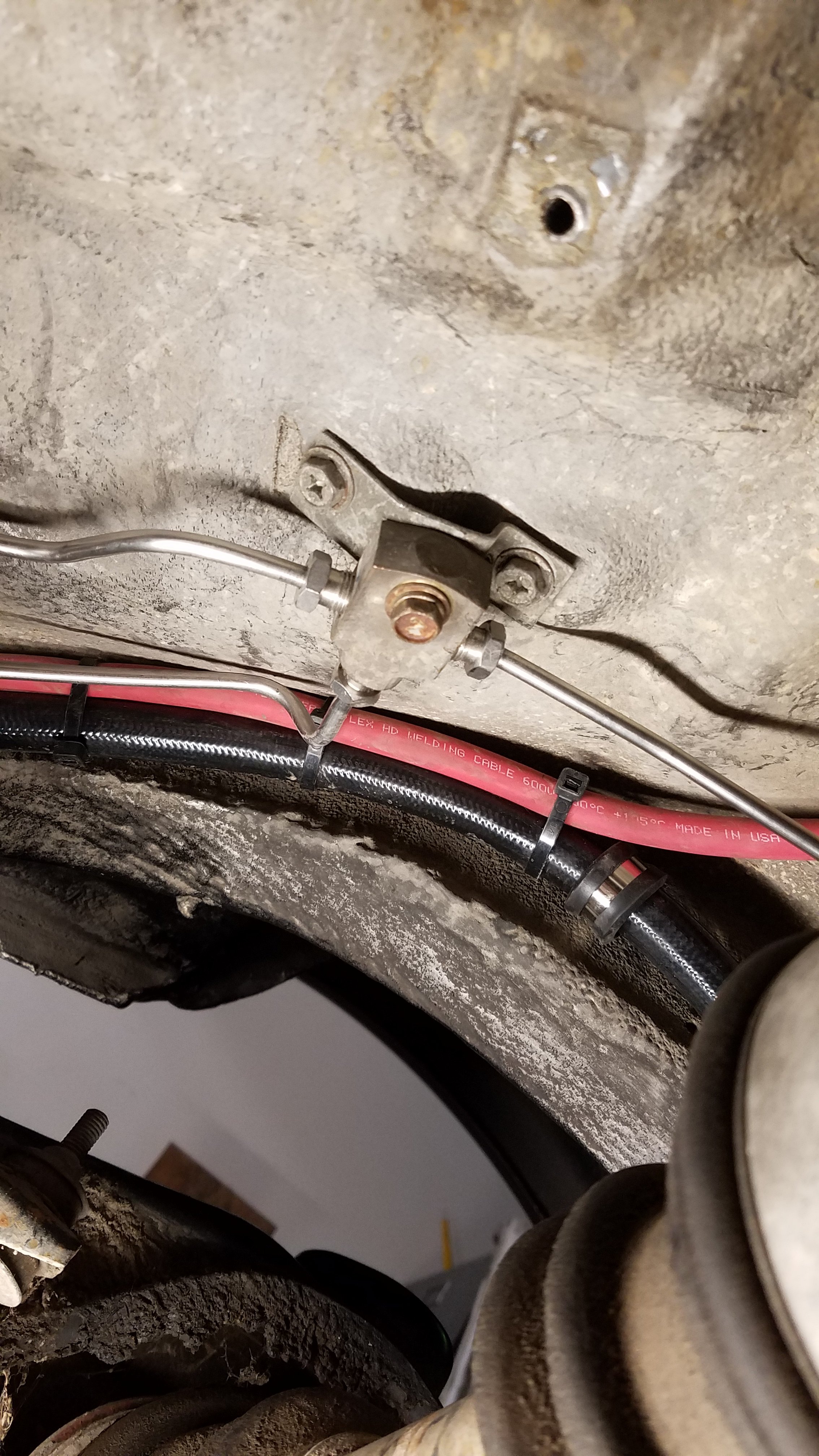
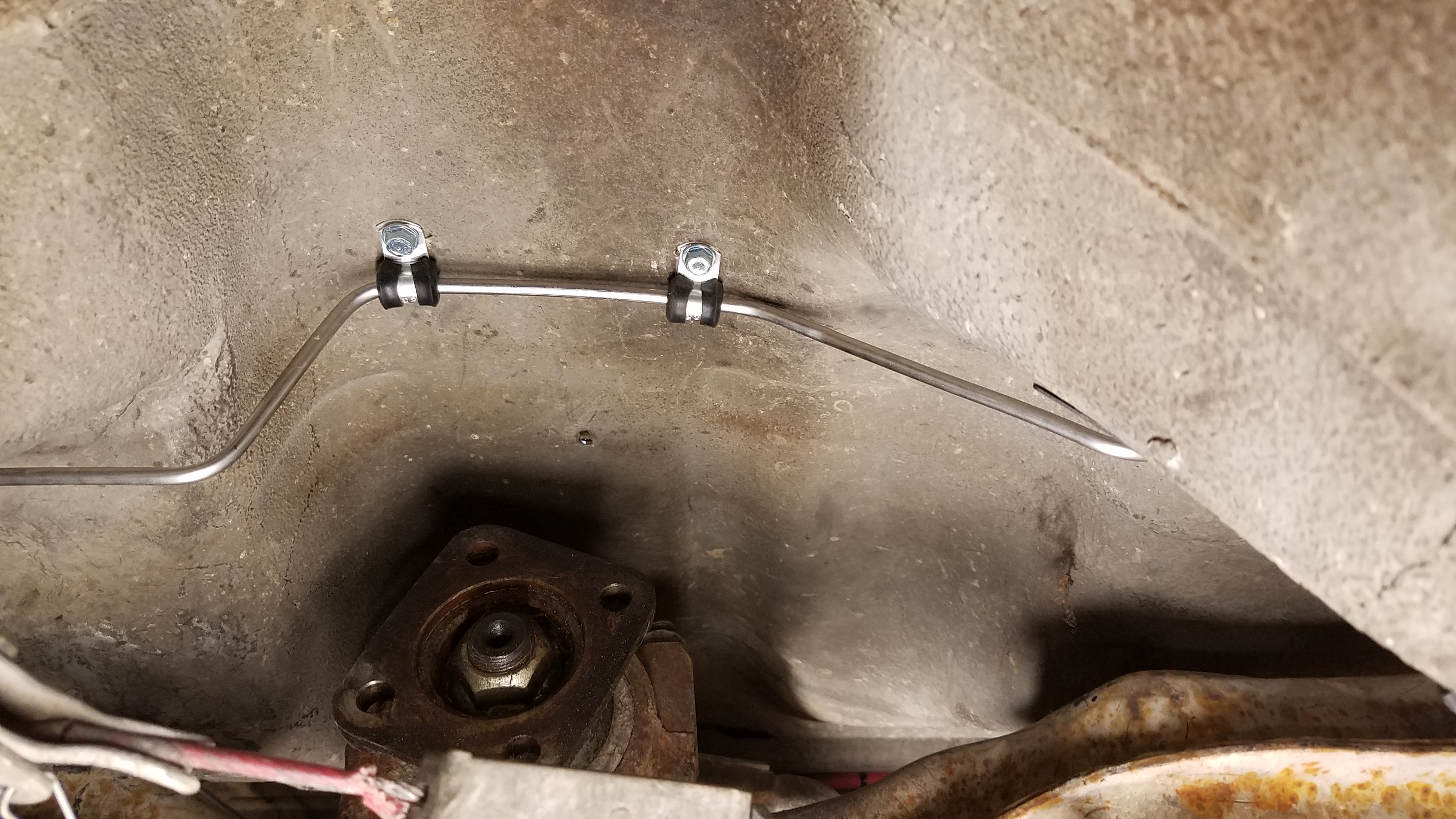
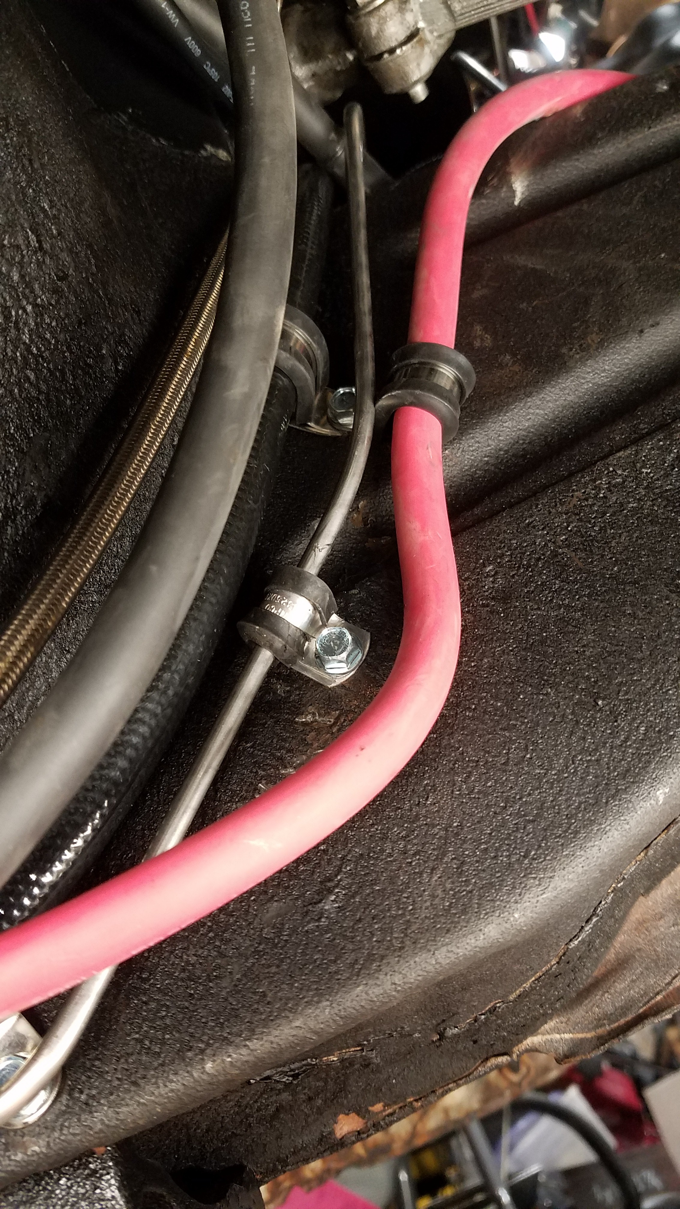
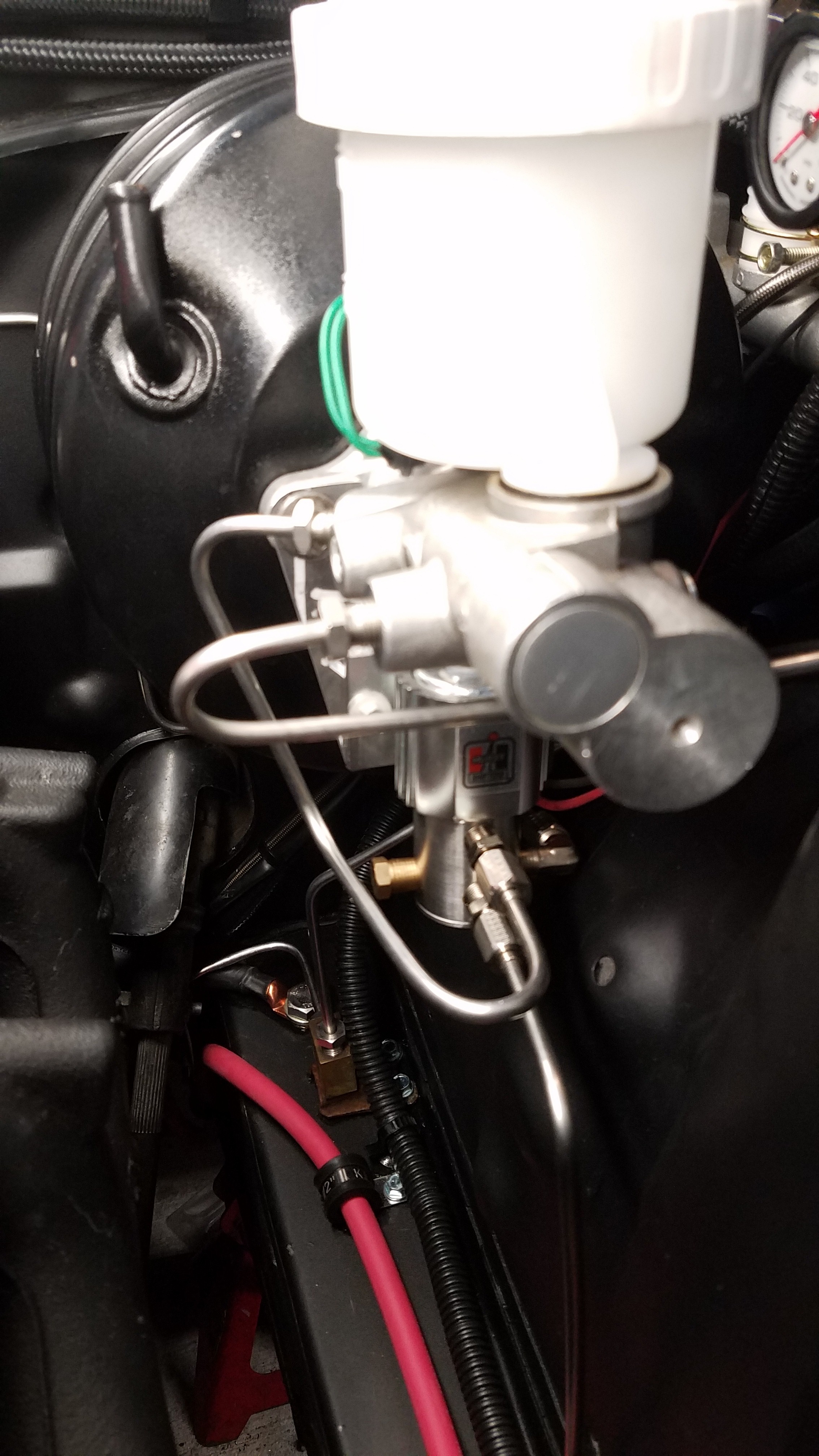
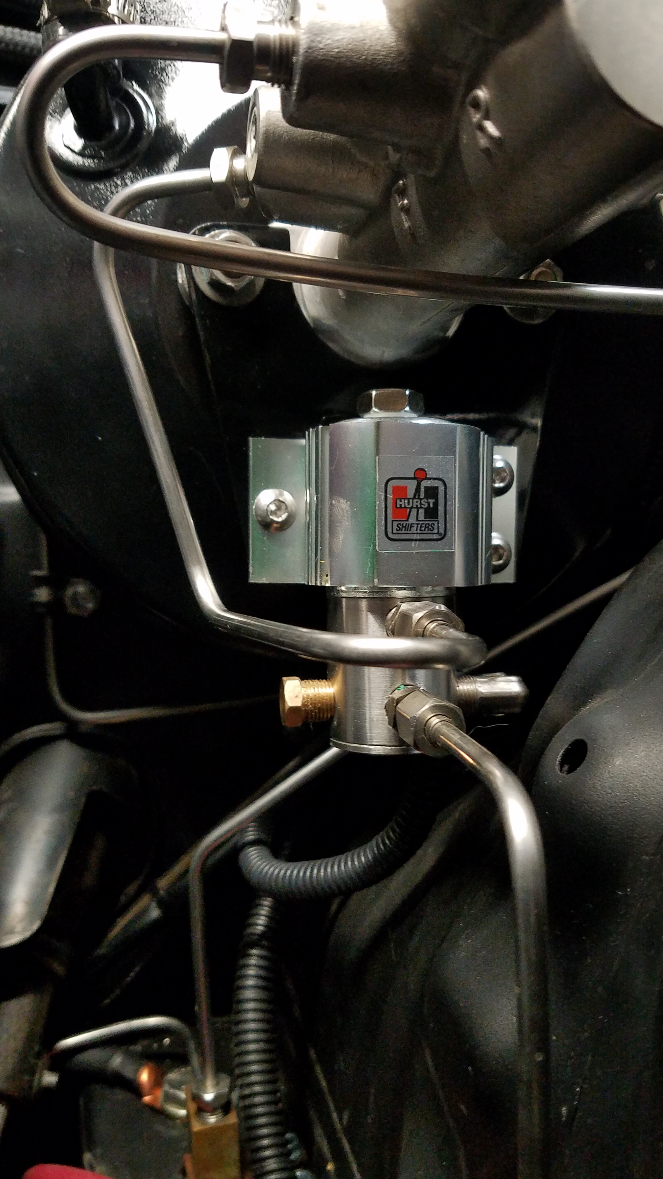
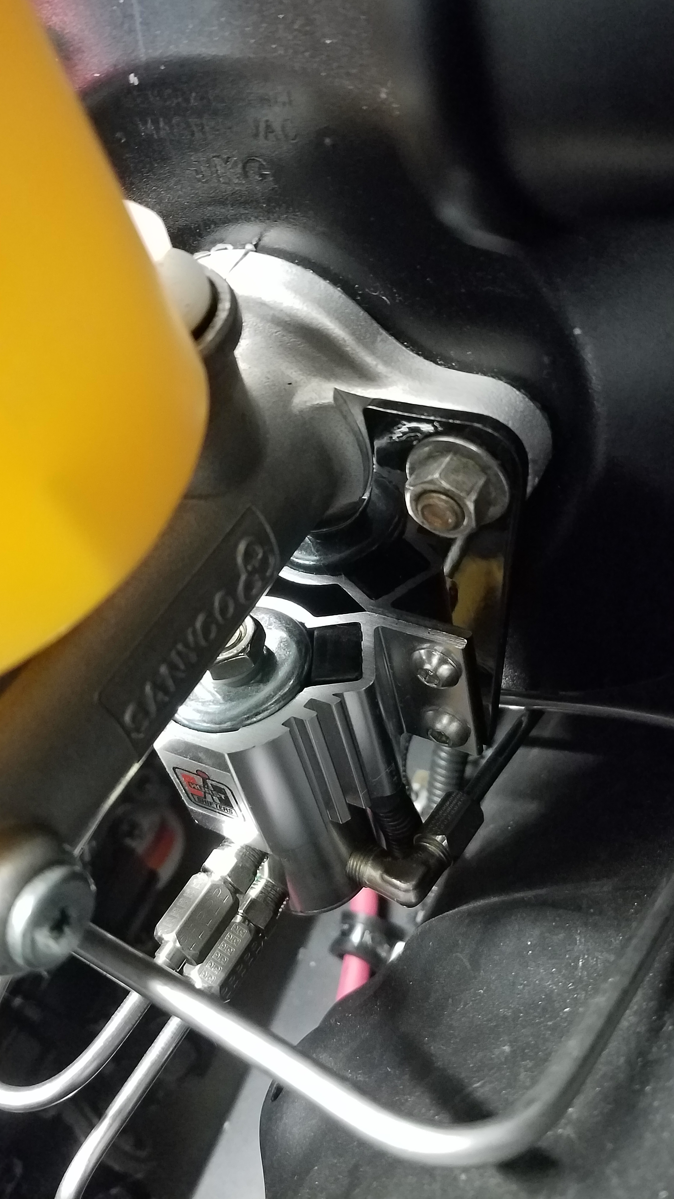
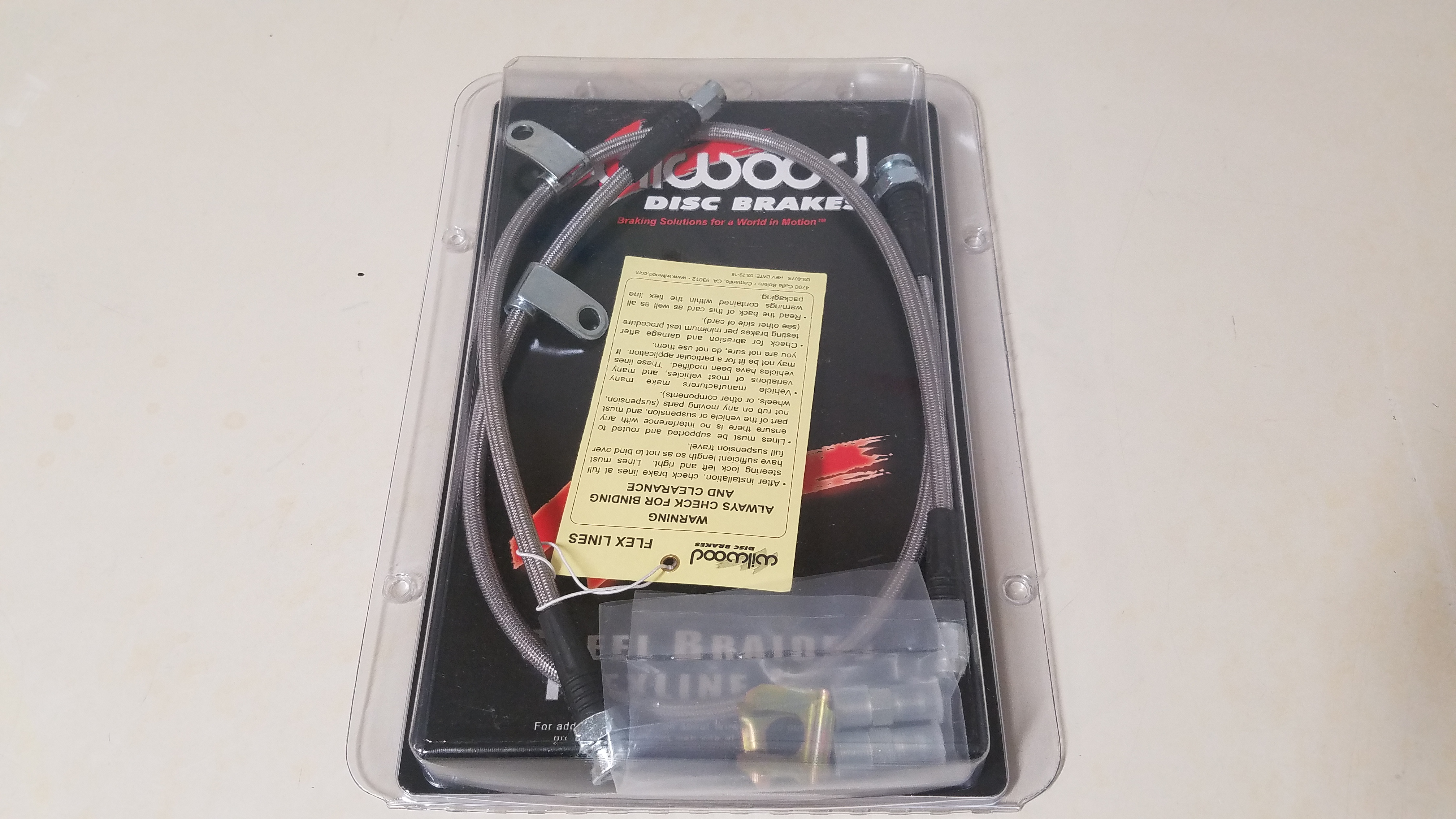
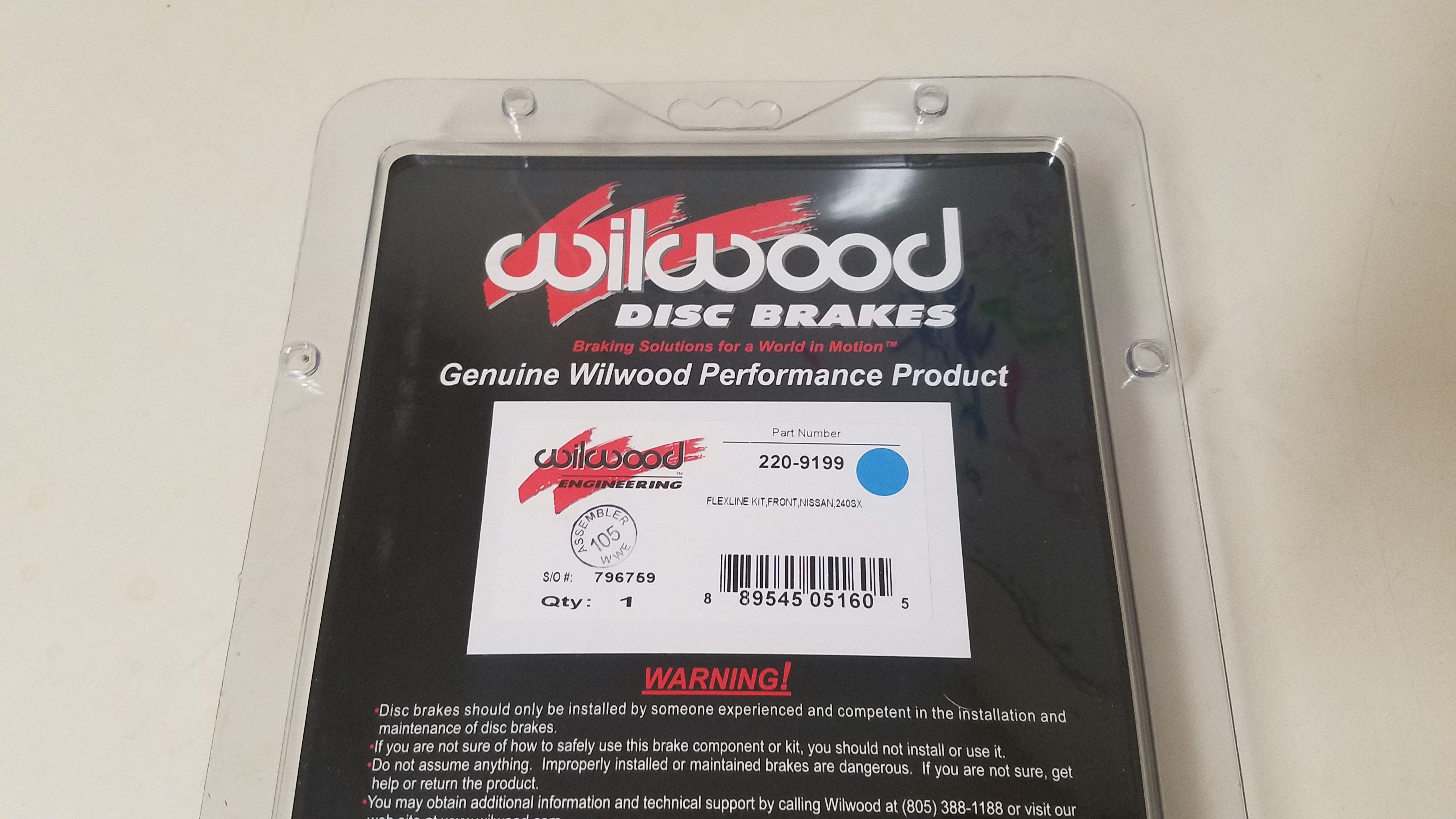
Picked up a Hurst line lock for the car too. Part# 174 5000. The installation of it could start after removing all the factory brake hard lines & rubber hoses. I wanted to keep it as close to the brake master as possible. So I made bracket that would locate the solenoid directly under the brake master. It would be secured using the same studs used to mount the brake master to the booster. This keeps it away from all heat sources & the amount of hardline down too. Construction of the brake hard lines could start with lock location officially set. 3/16 stainless steel hard line was used to make every brake line in the entire system. To minimize the amount of clutter on the firewall I ran the rear brake line down the drivers frame rail instead of the passenger side. Only hard line that runs along the firewall is for the passenger front caliper. After all the hard lines were made the line lock bracket was painted for a cleaner look. With stainless steel hard lines knocked out Wilwood stainless steel braid brake lines were installed for the front calipers. Wilwood hose part # 220-9199
-
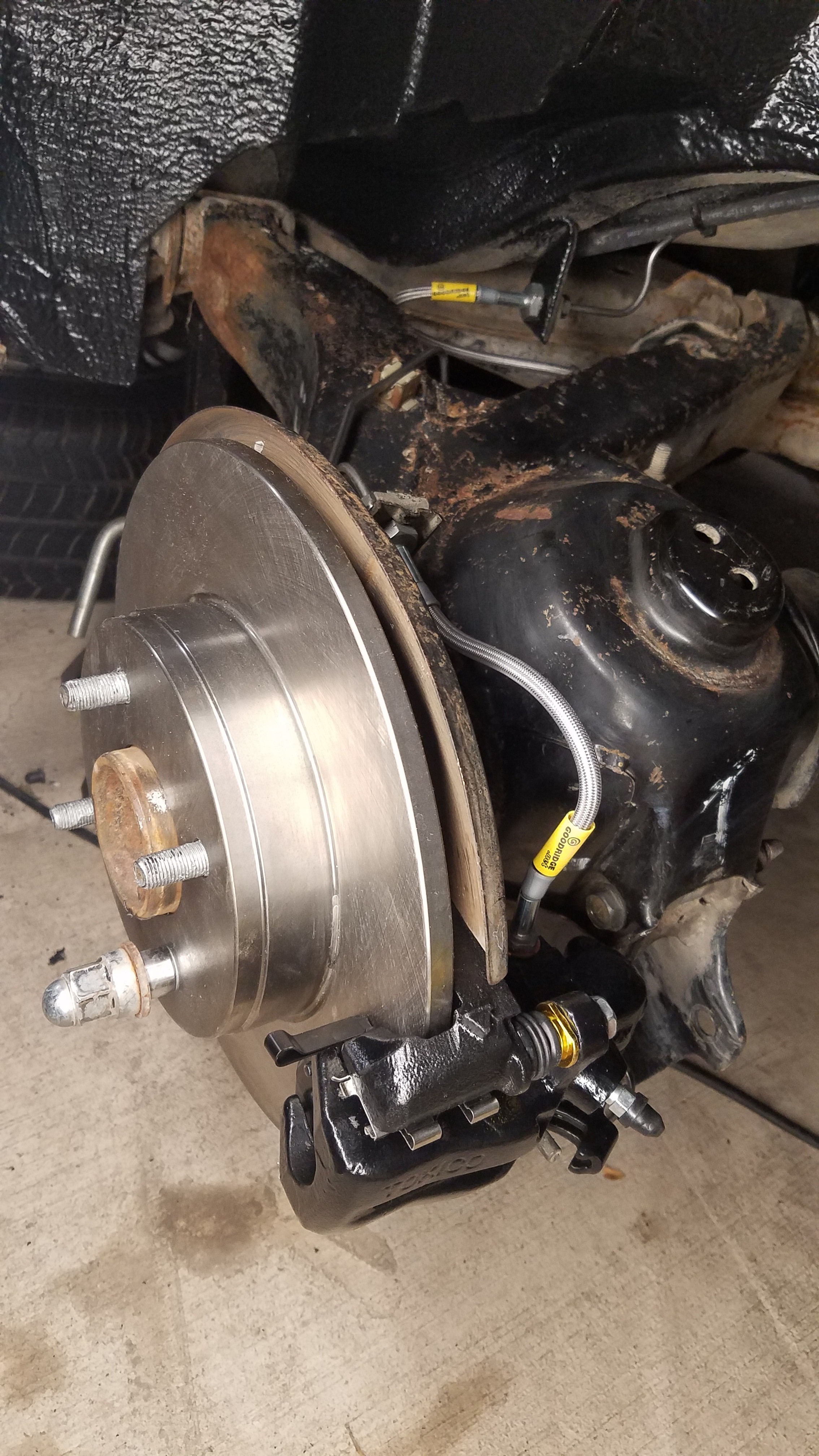
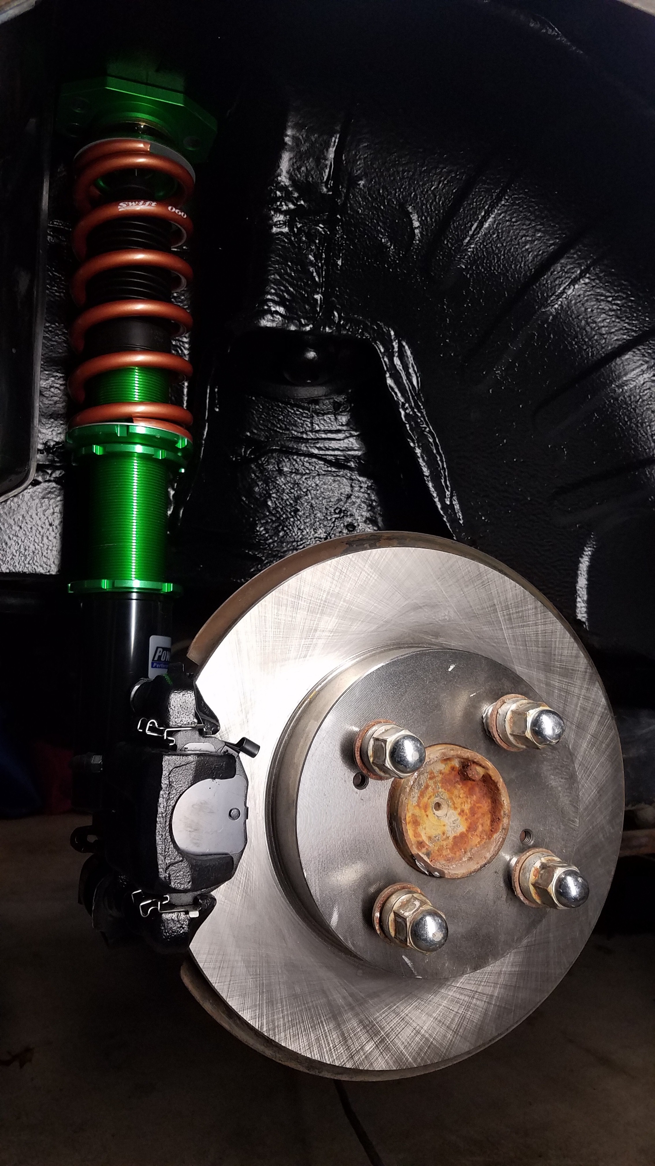
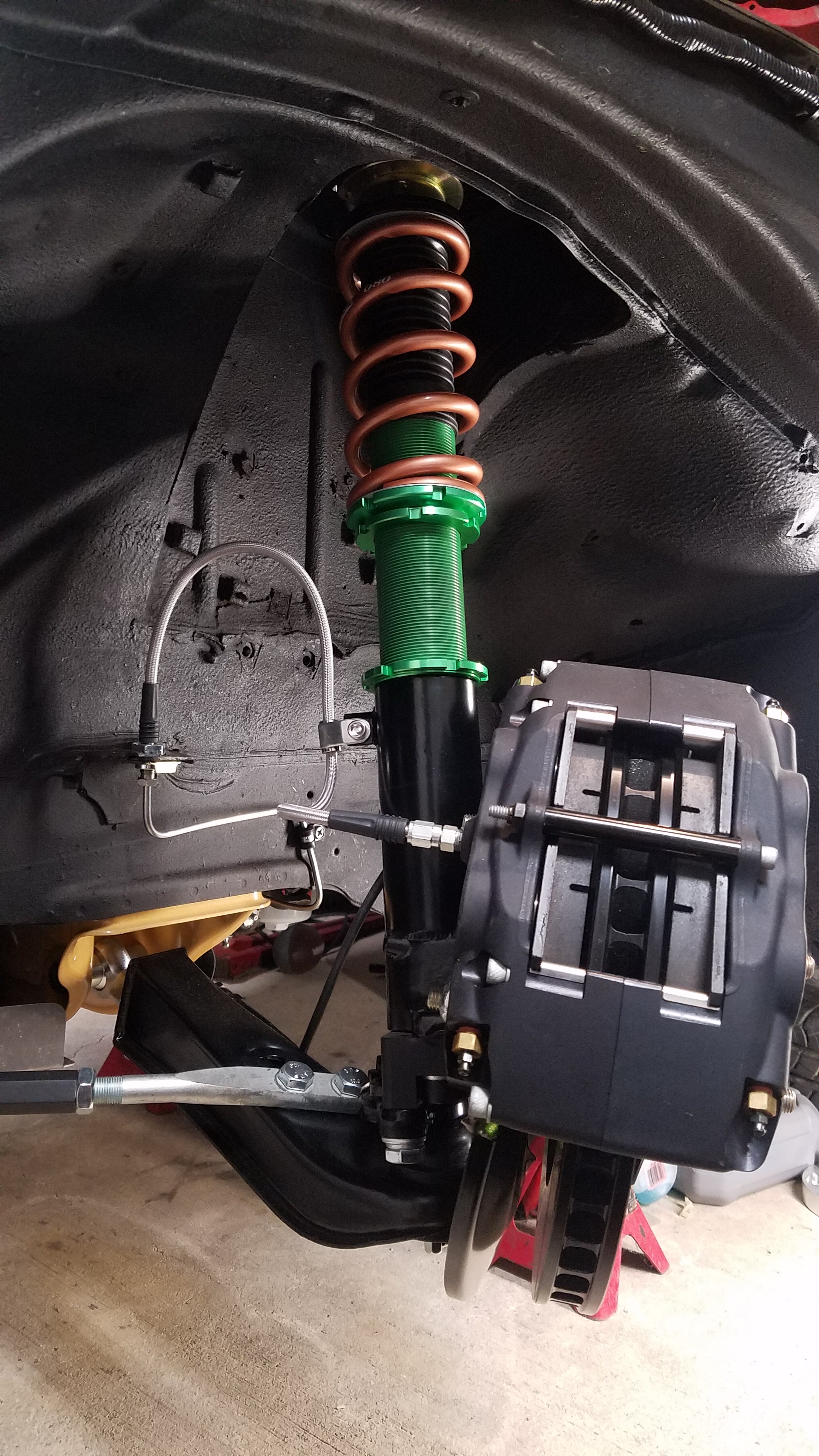
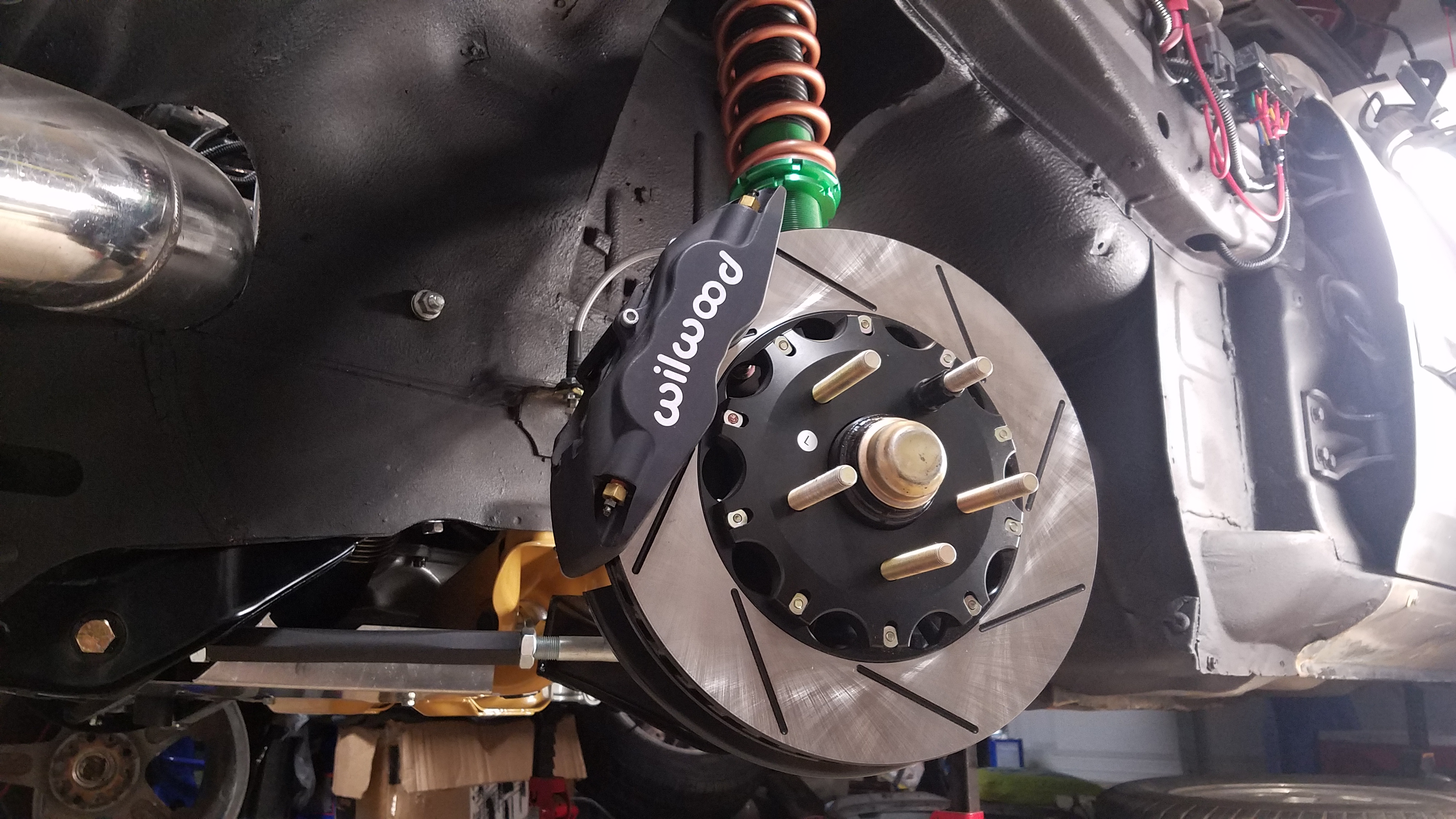
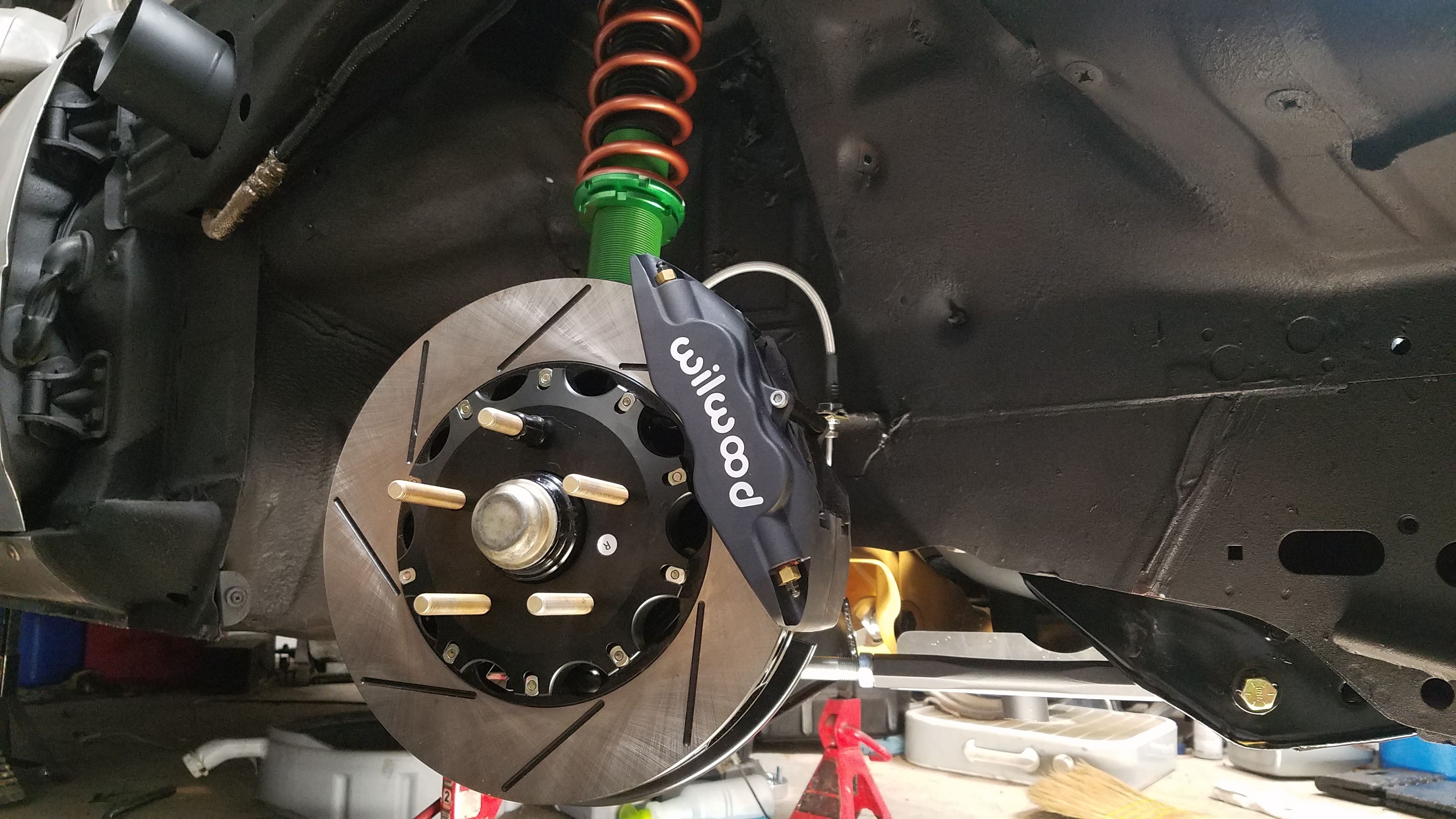
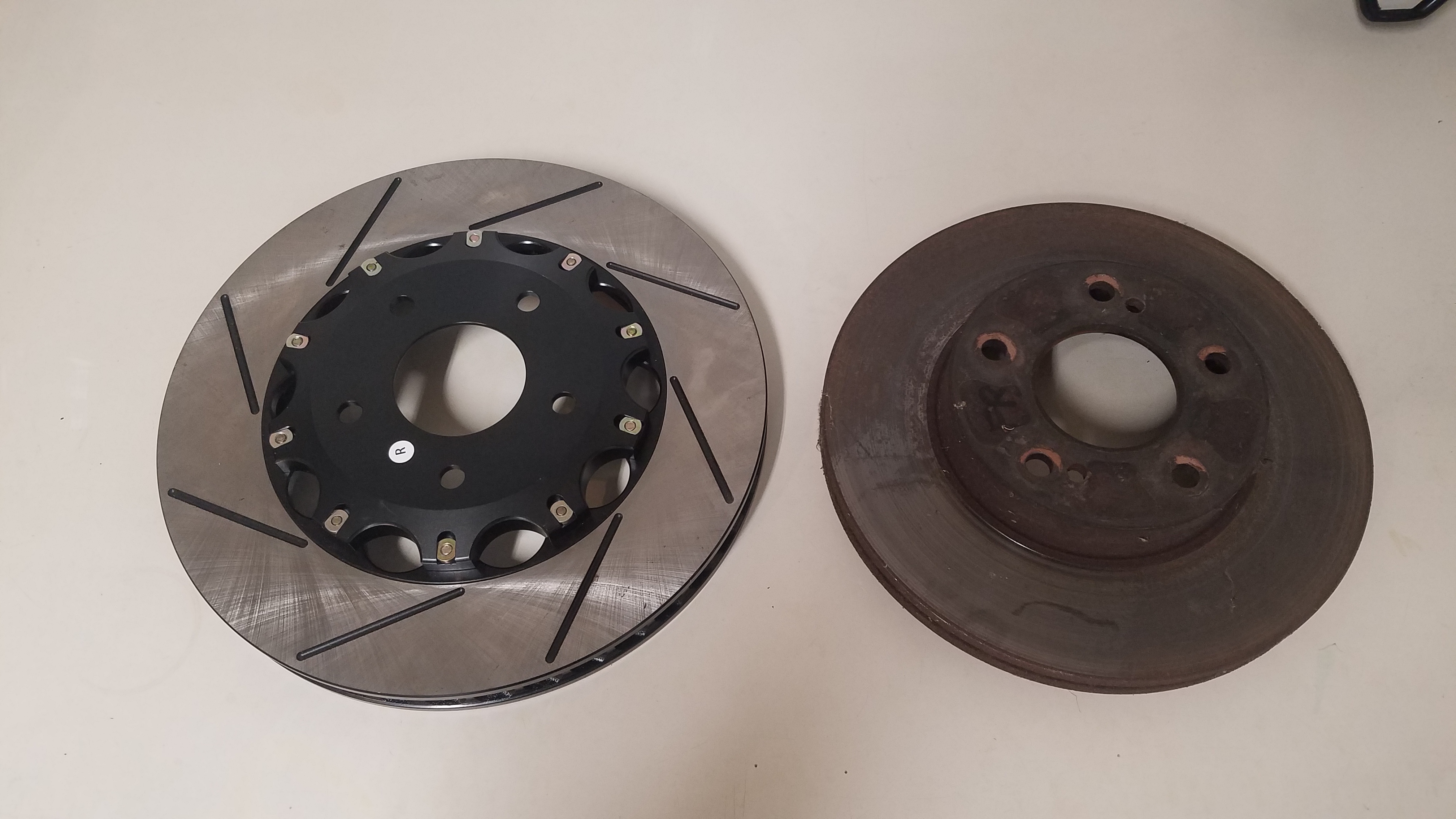
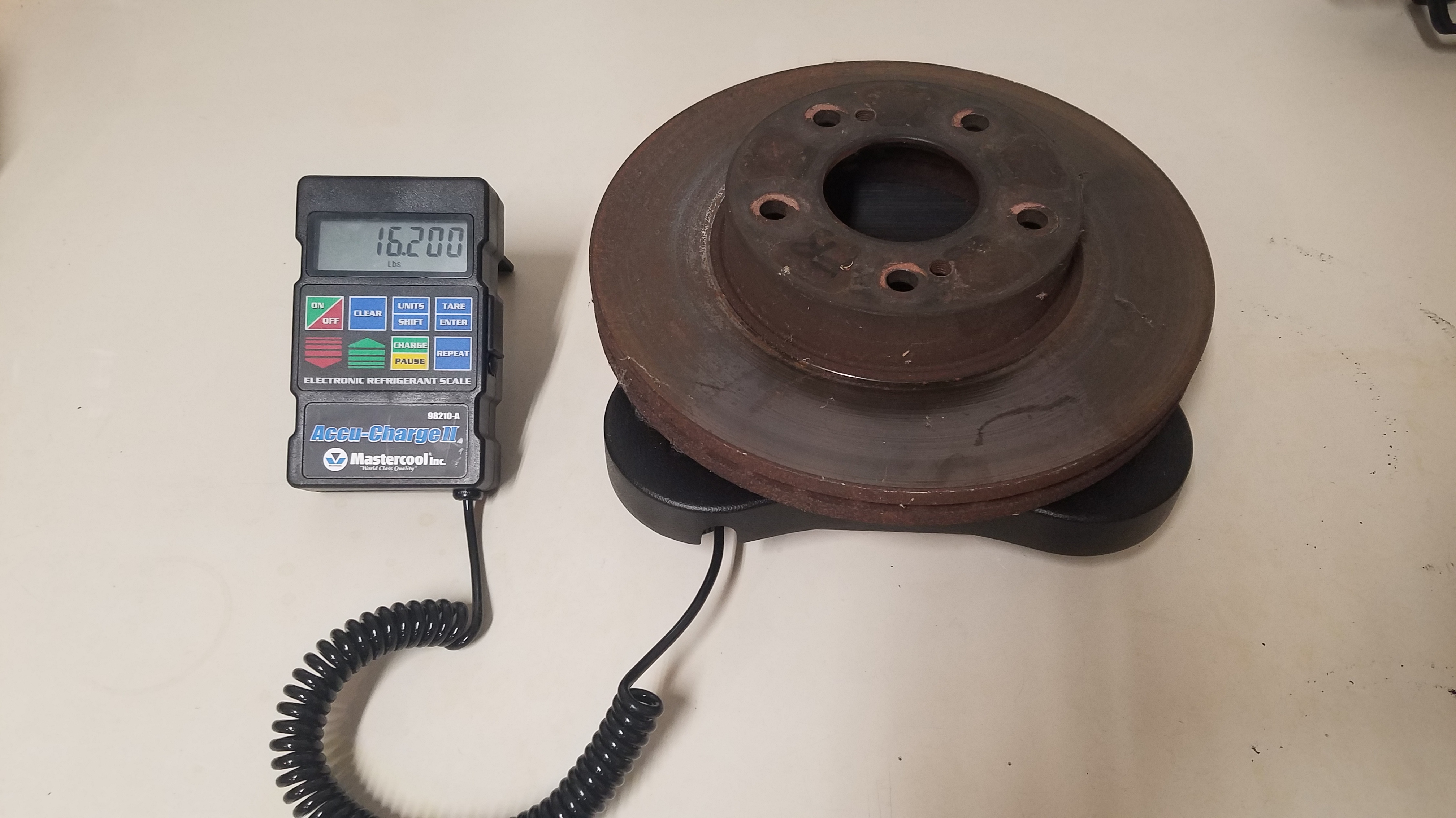
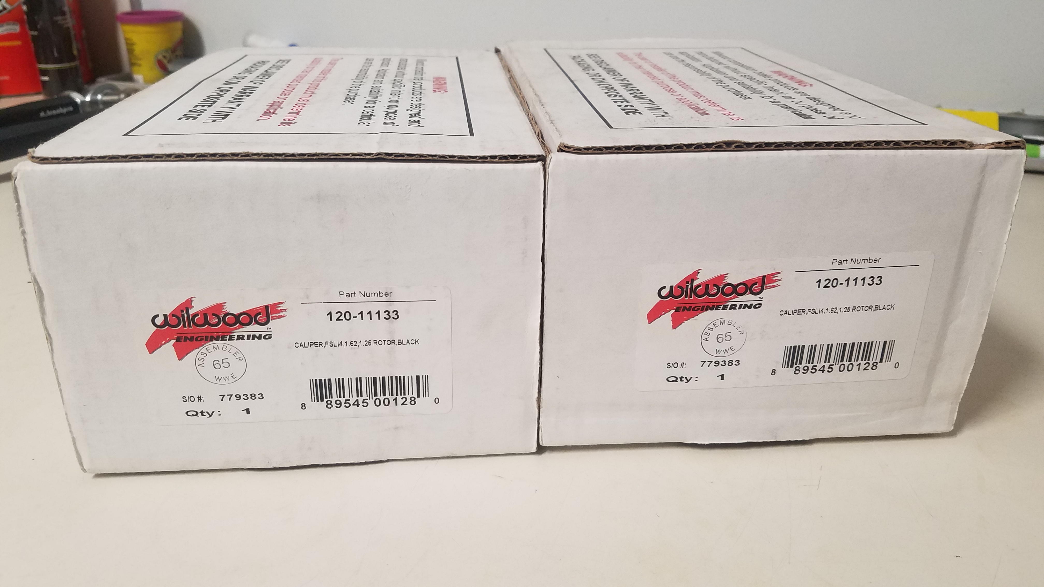
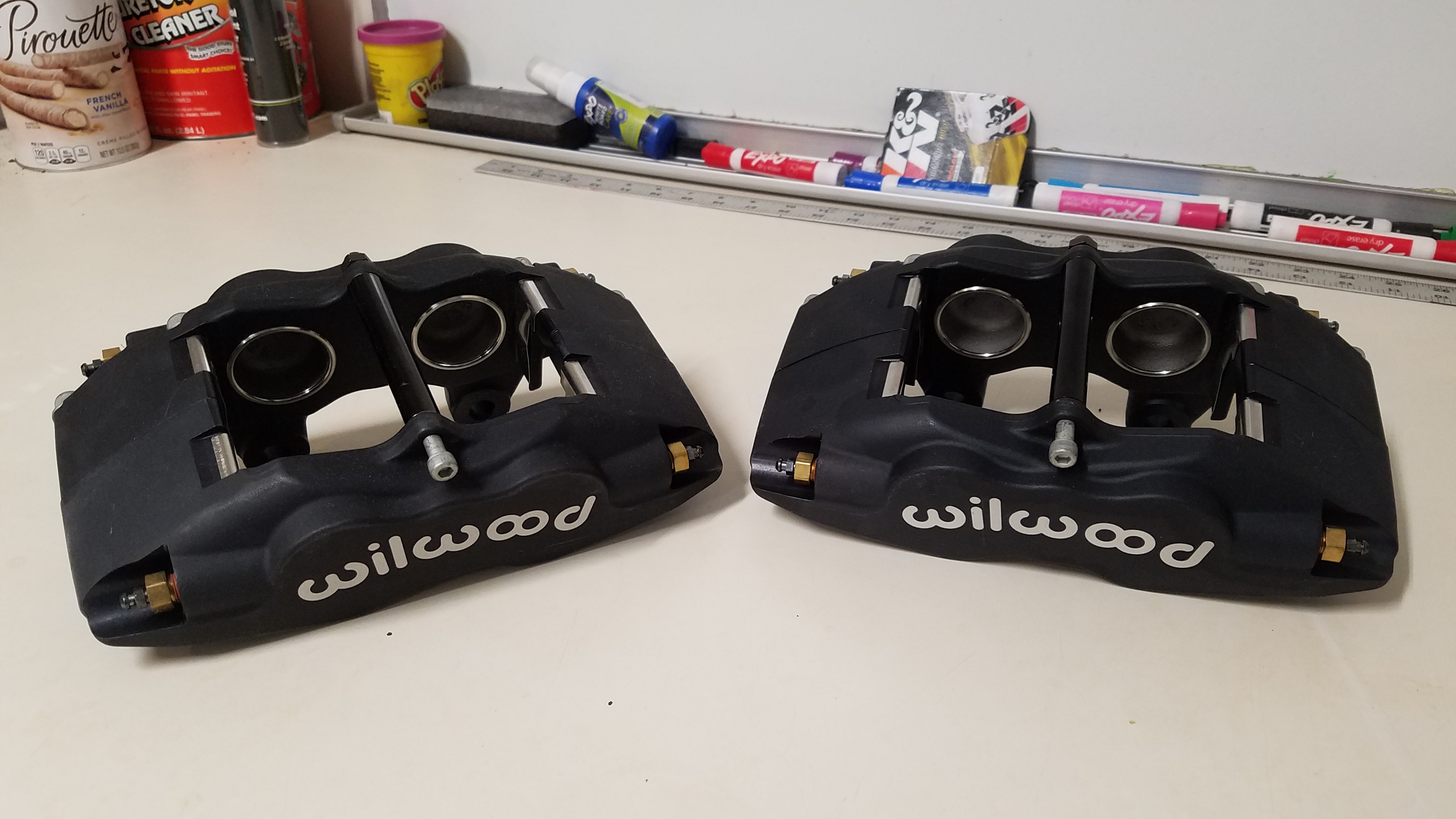
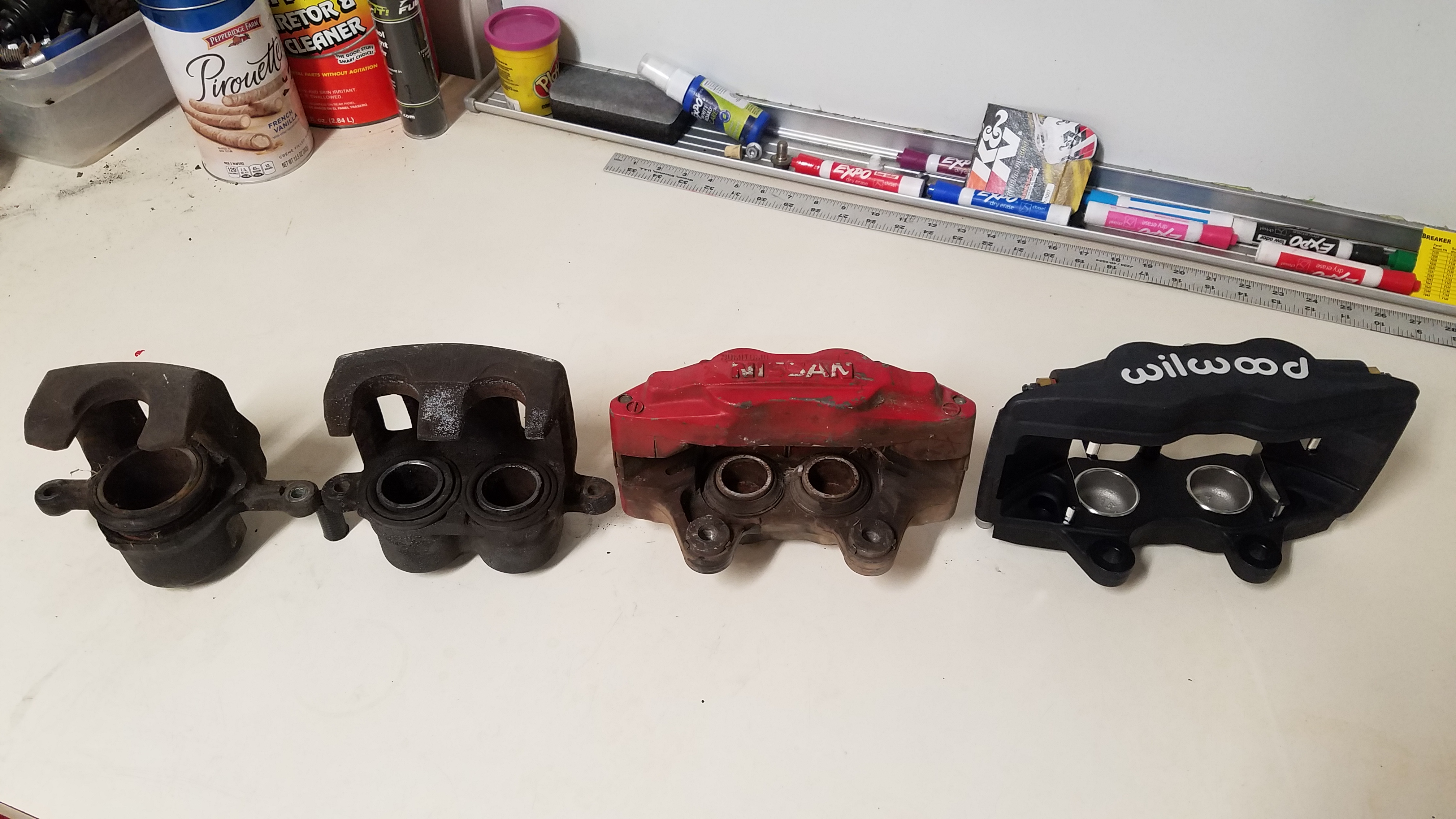
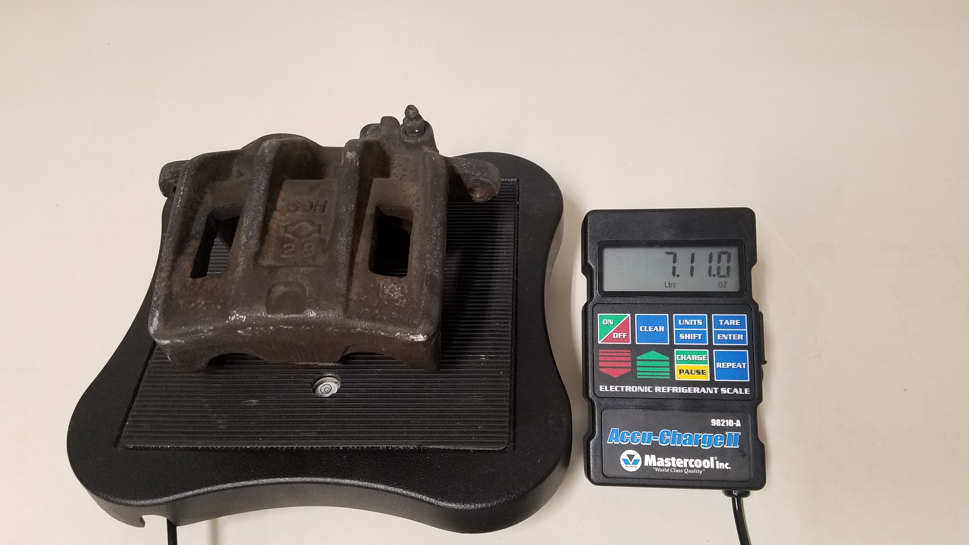
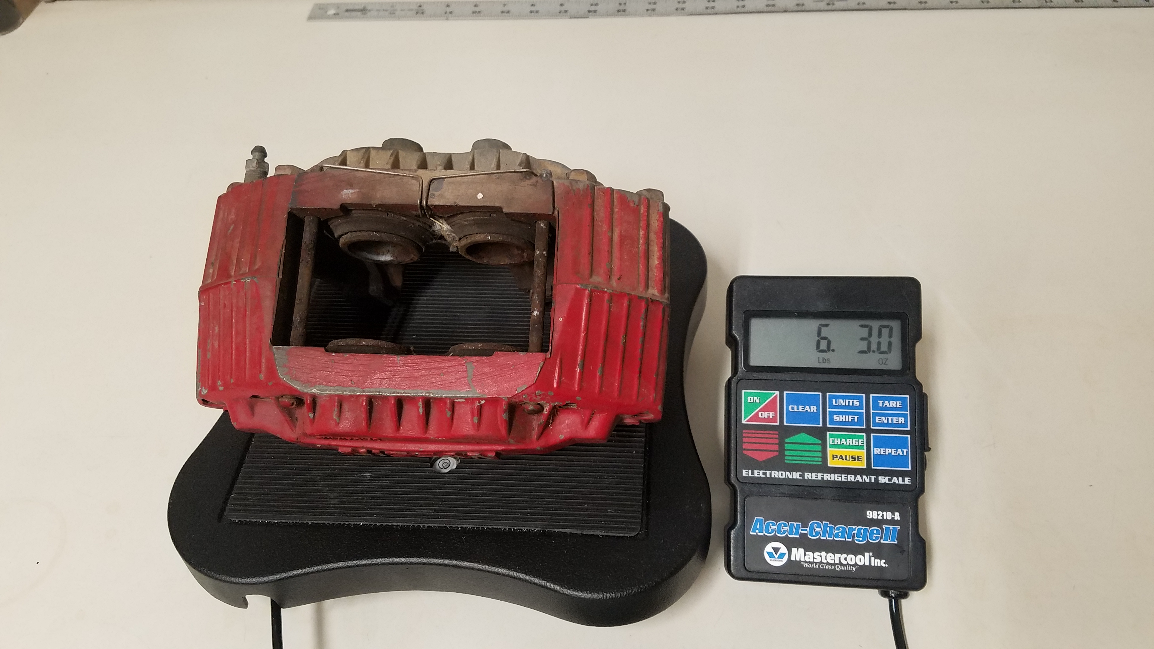
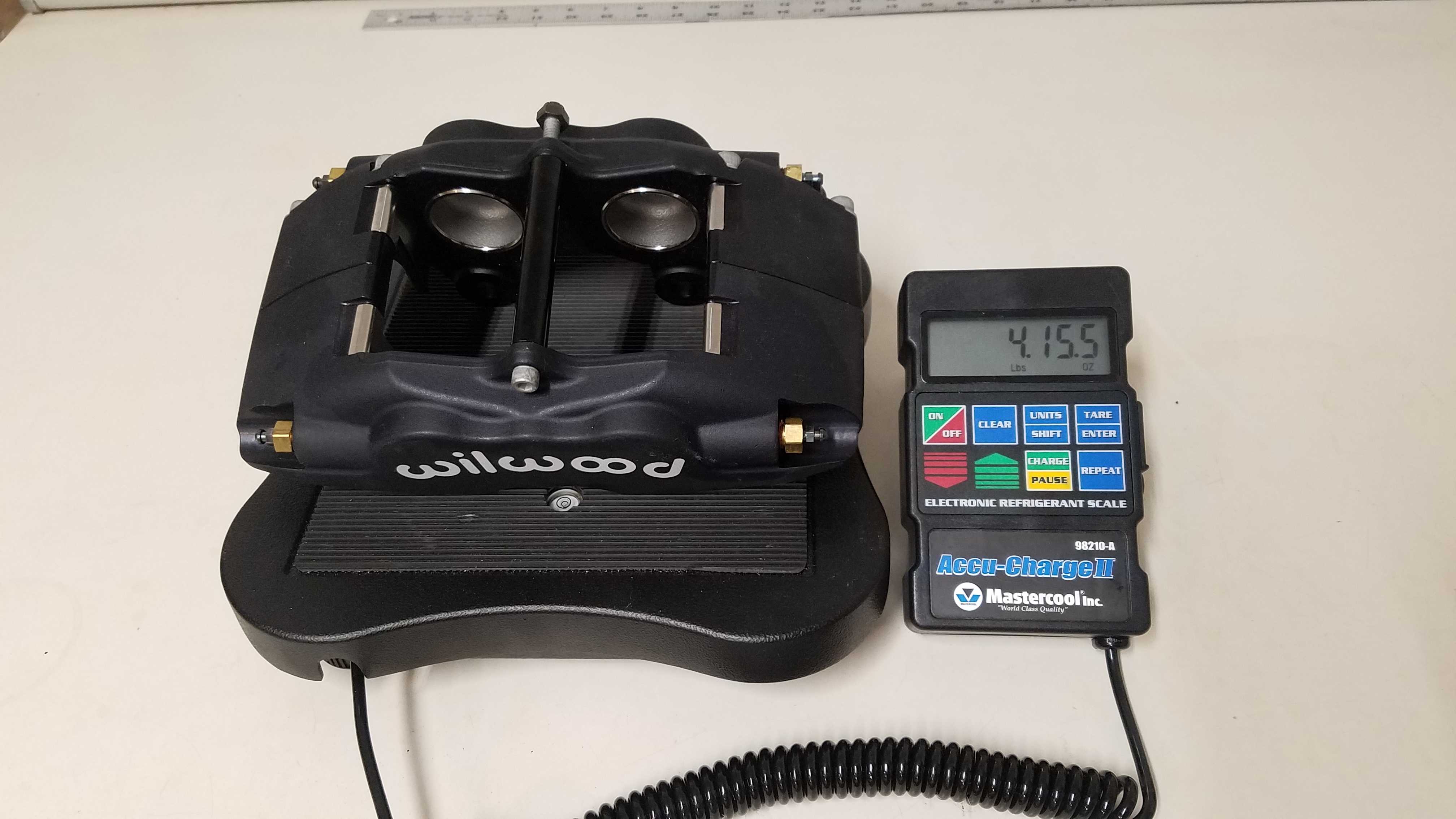
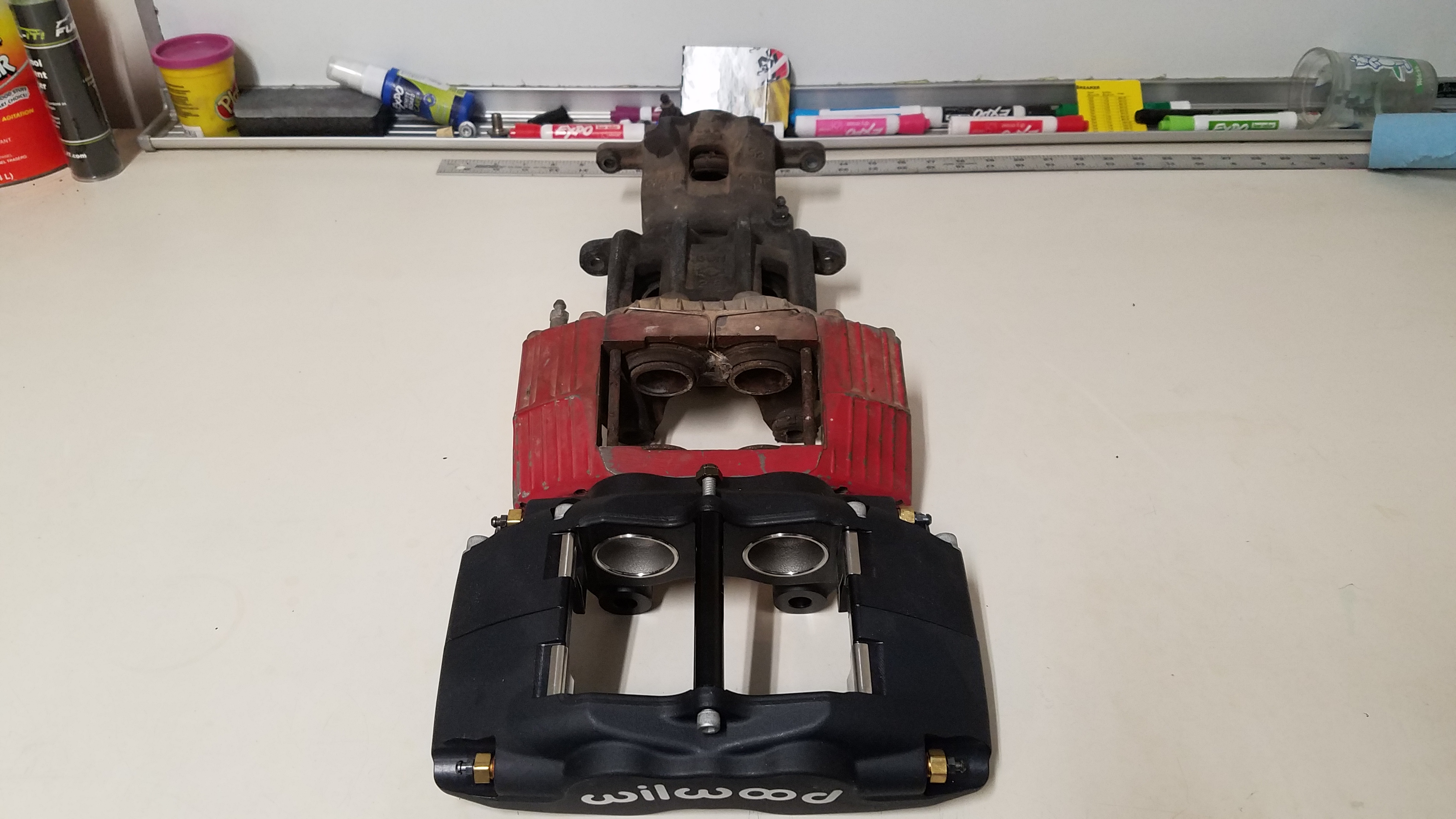
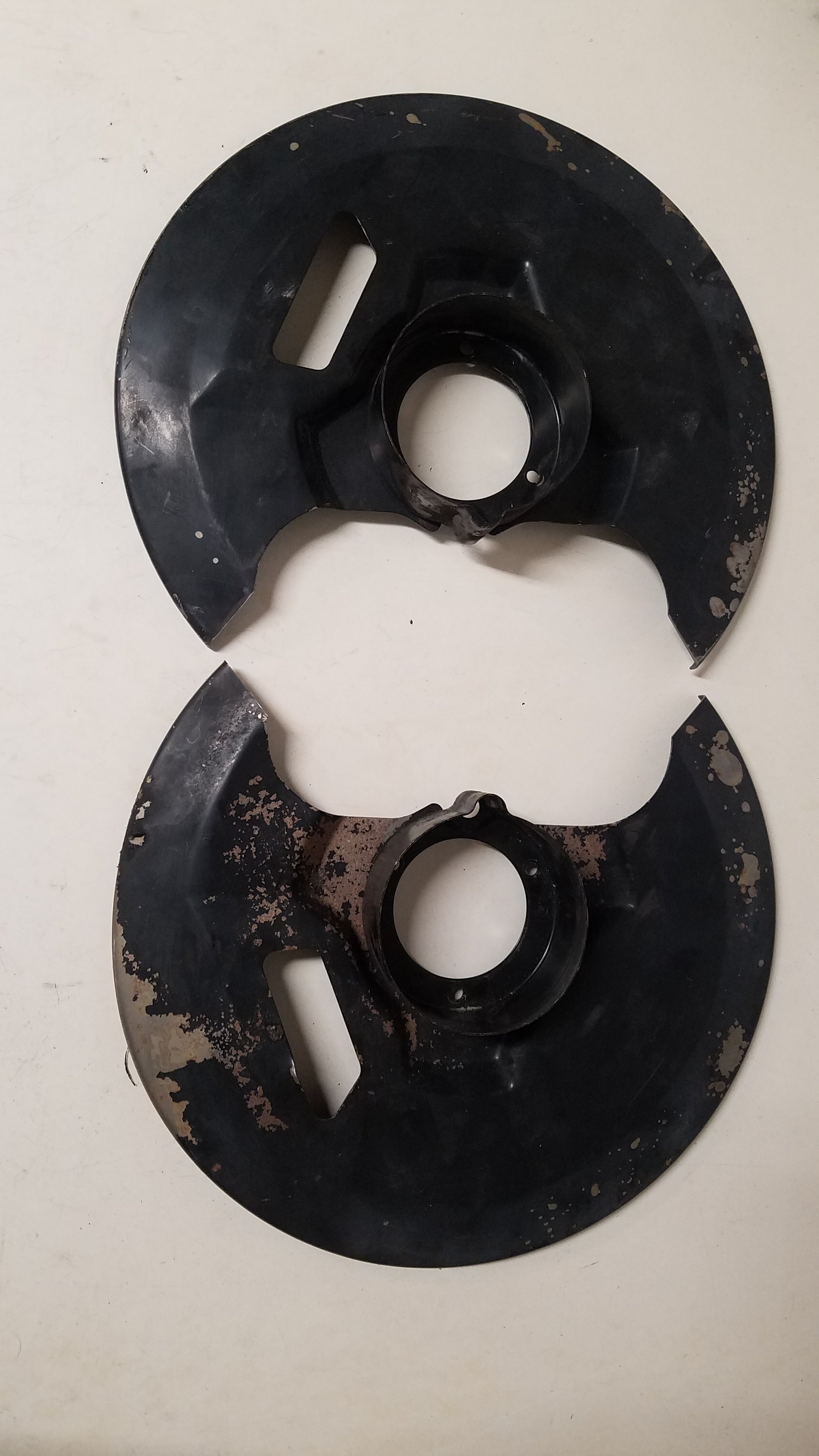
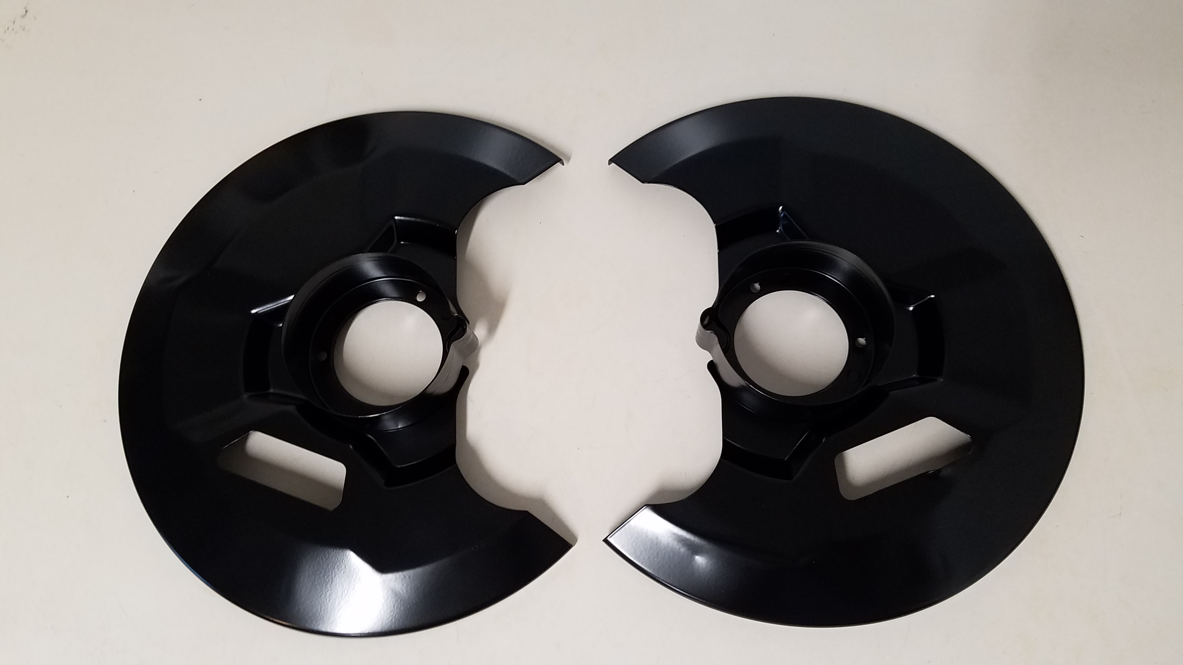
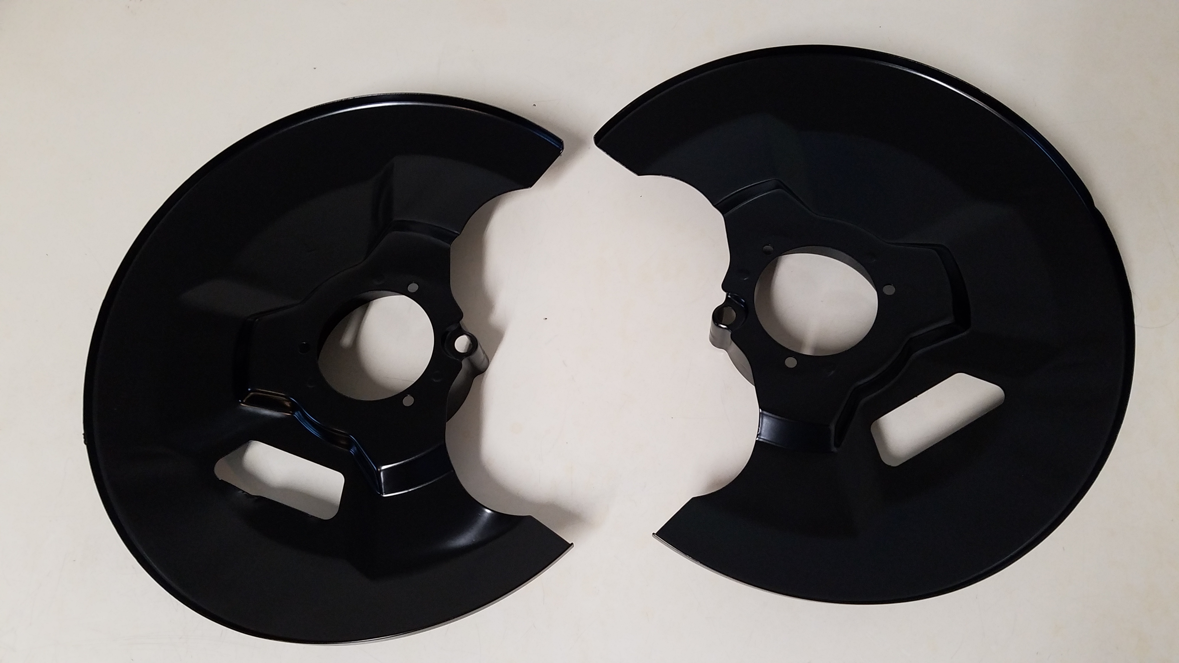
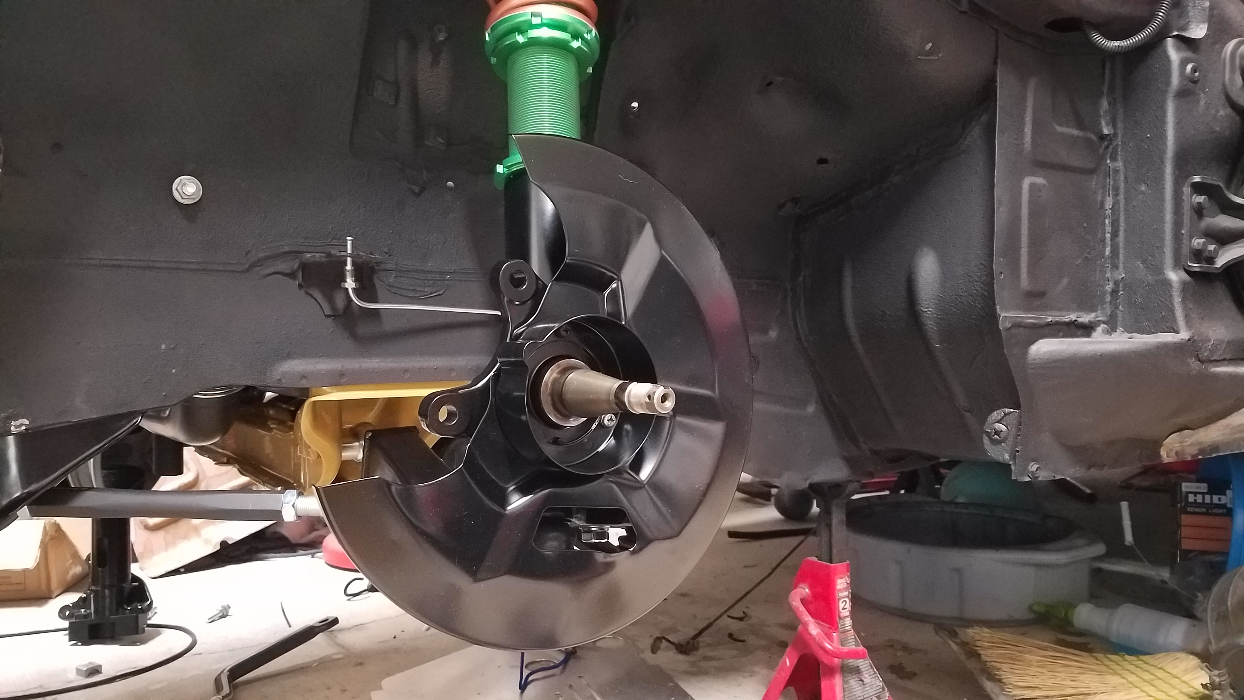
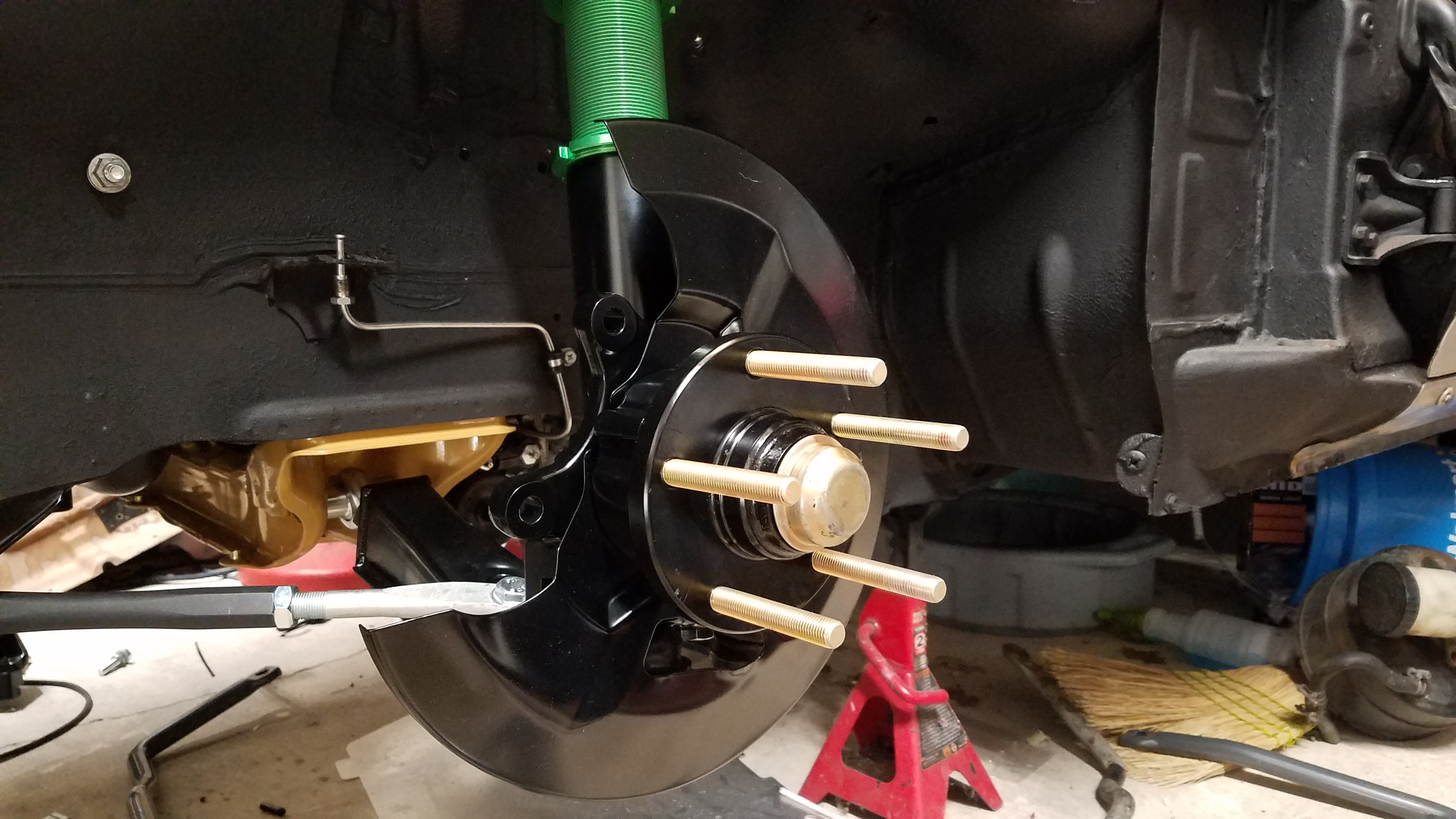
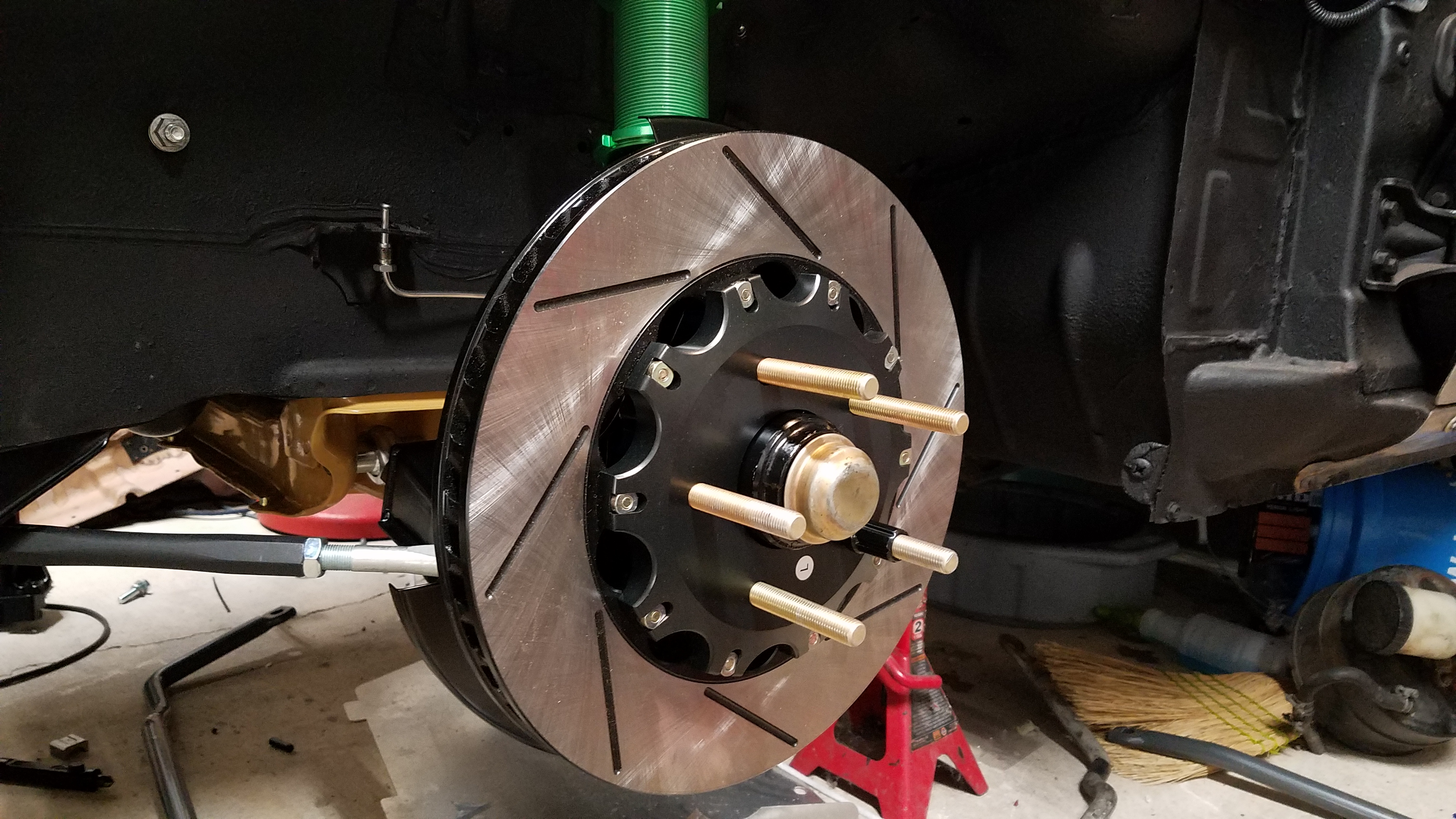
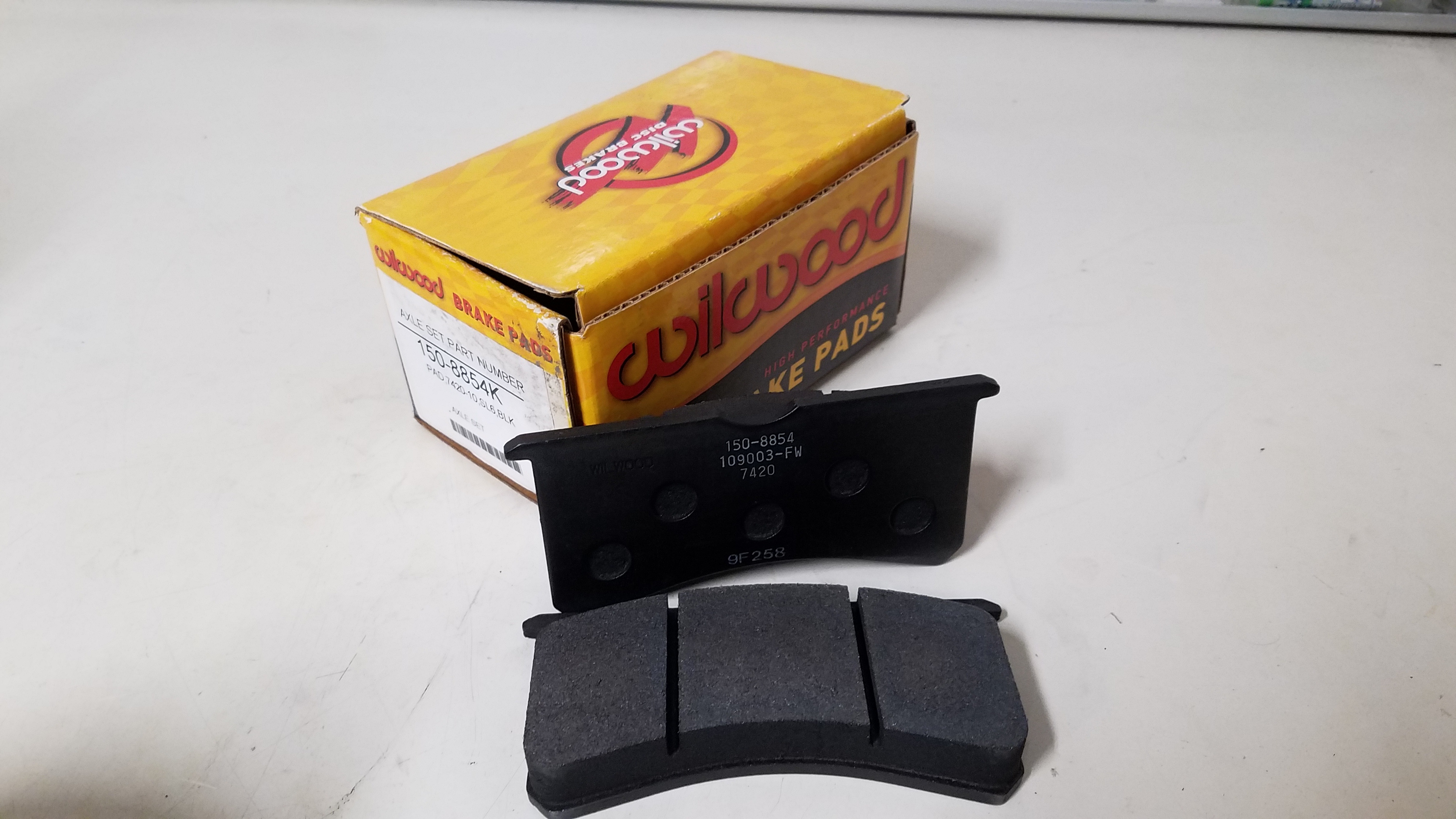
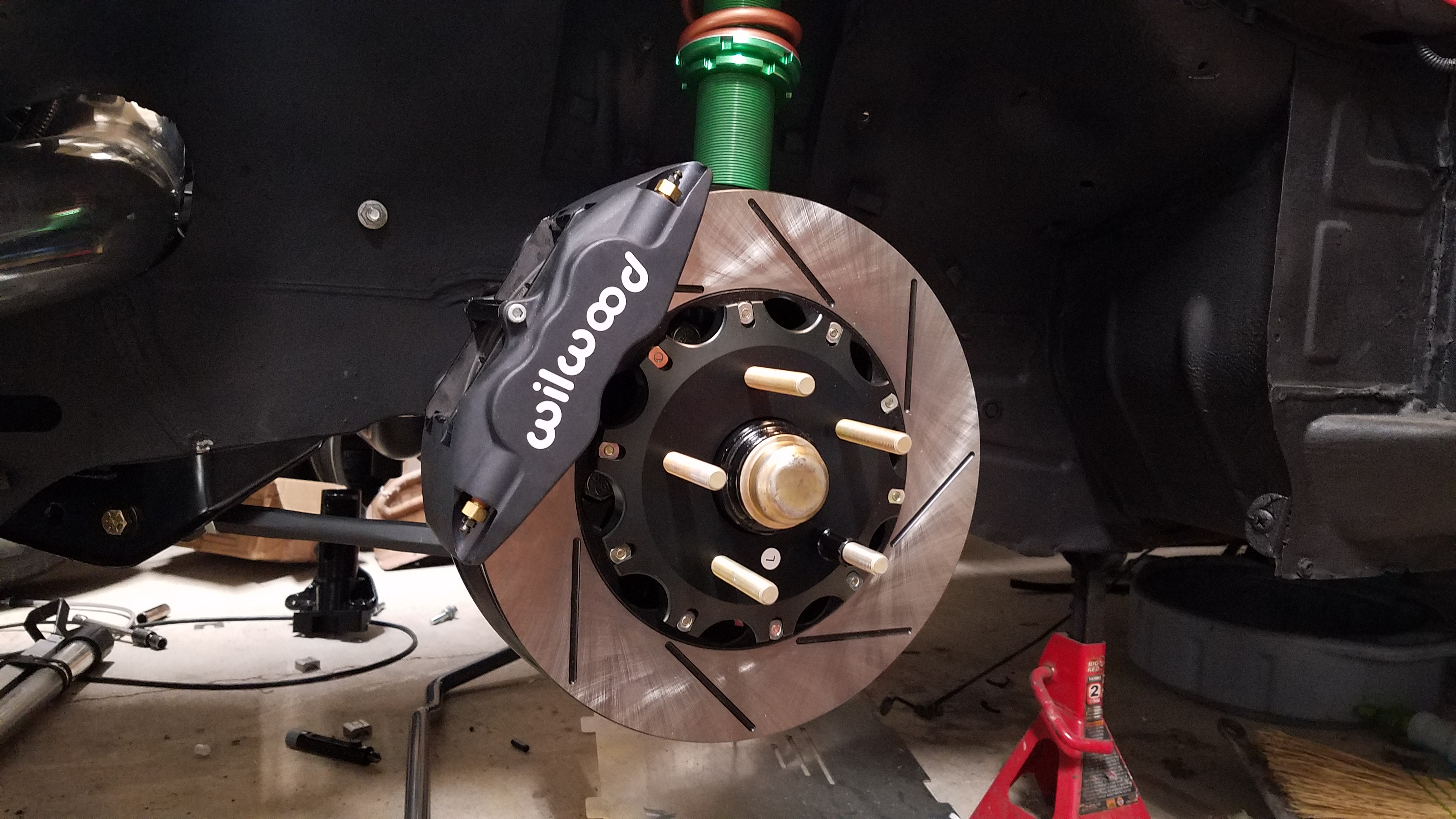
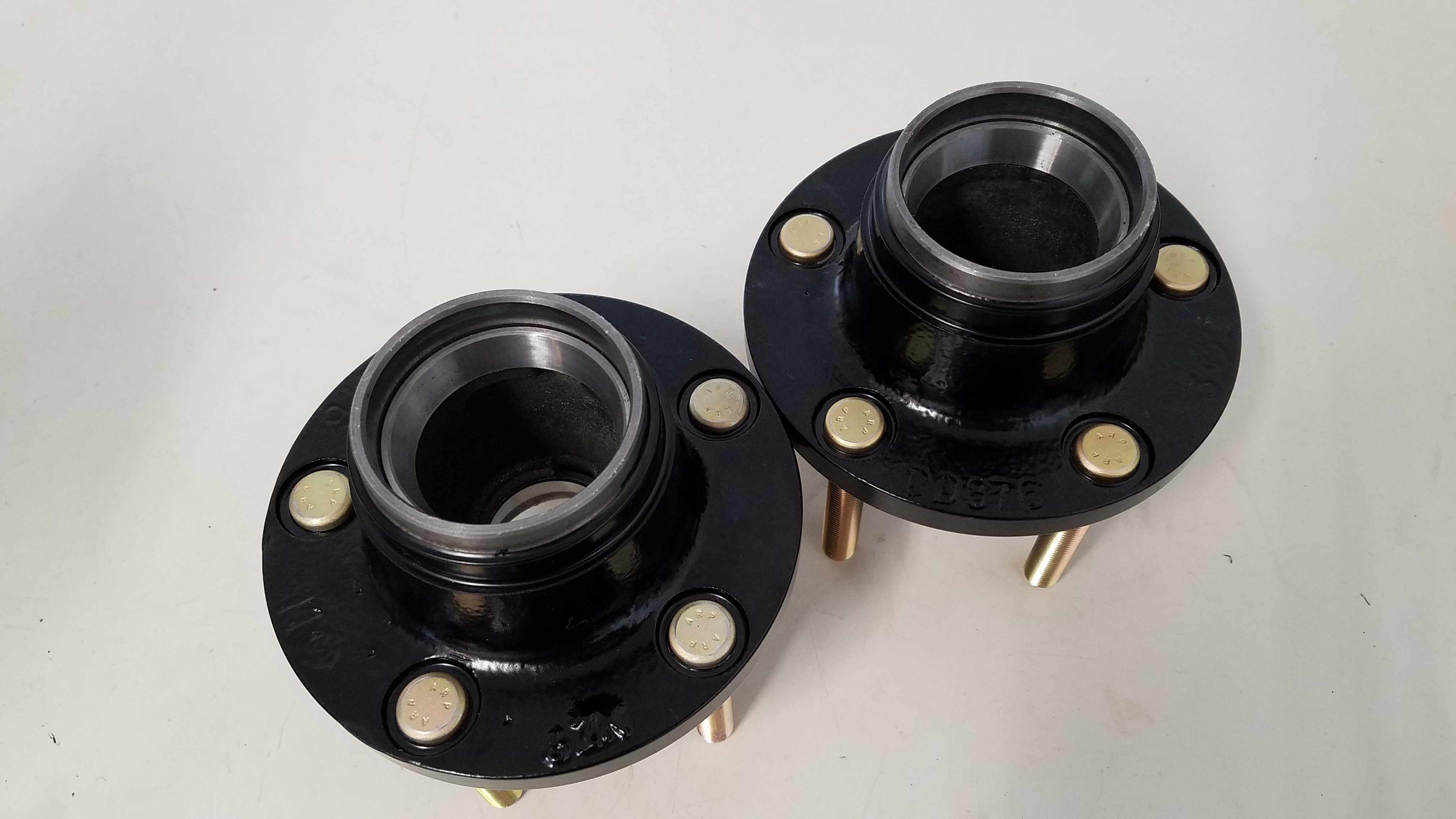
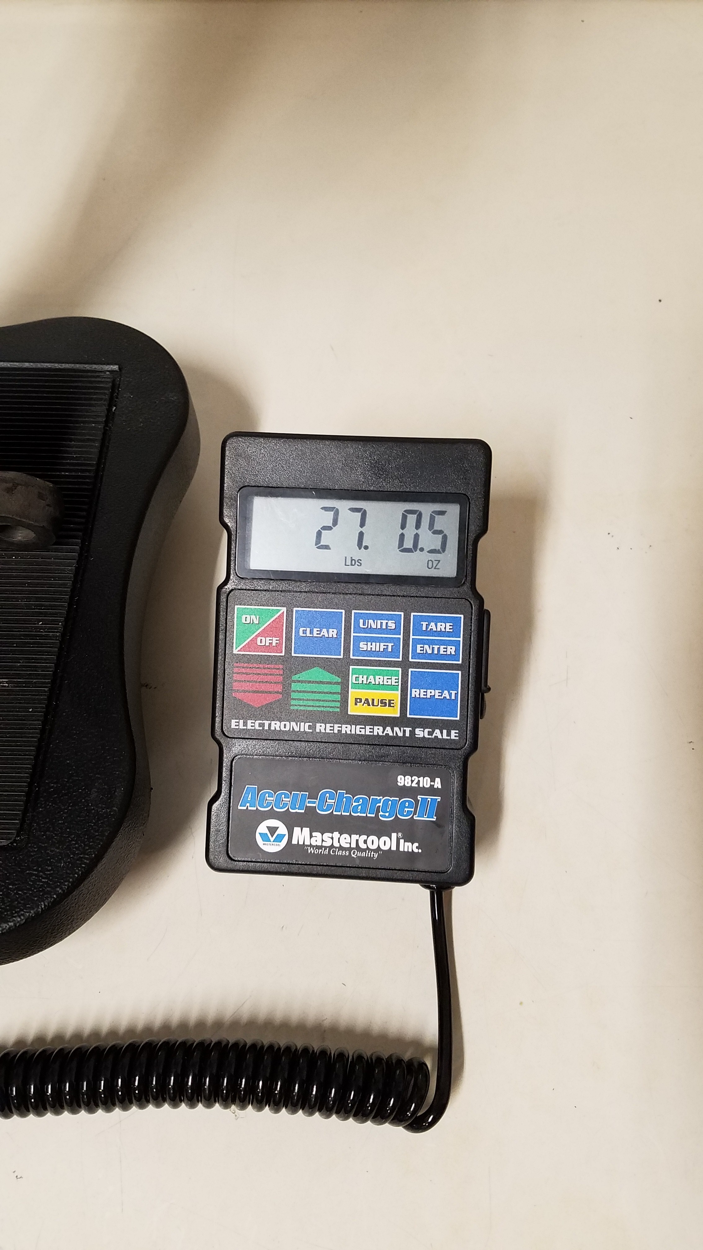
I explored several different front brake caliper solutions. Many were just larger factory calipers from other . I.E. Evo 8/9 calipers, 350z (Z33) Brembos, Akebono style calipers. On my previous car I had Z32 (90-96 300zx) brake calipers. I also already had a set of Z32 calipers & Z33 Brembos. But I decided to go another route for this car/to try something "new" to me. Wilwood Superlites grabbed my attention immediately. Their main selling points IMO were the calipers piston size, weight savings & variety of different brake pads compounds to choose from. Luckily my buddy Adam had already shared what was all needed with The Z31 community. He even held a group buy for the brackets needed for the install. The Wilwoods I purchased were part# 120-11133. Intrigued by how light Wilwoods felt. I broke out my scale so I can do a weight comparison between the 4 different calipers in my possession. This comparison covered 84 N/A, 88 Turbo, 30mm aluminum Z32, & Willwood Superlite. Unfortunately I forgot to include the Z33 Brembos for what ever reason. By the time realised This I had already sold them. Here's some comparison photos. These were weights from lightest to heaviest. All weights are for an individual caliper that was fully drained. 1) Wilwood Superlite 4 piston caliper @ 4LB 15.5OZ 2) 84 N/A Z31 single piston caliper @ 5LB 15OZ 3) 30mm aluminum Z32 4 piston caliper @ 6LB 3OZ 4) 88 Turbo Z31 2 piston caliper @ 7LB 11OZ Going into this I already knew the brake dust shields would need to be slightly trimmed to accommodate the Willwoods. Once the shield modifications concluded they were powder coated & installed. Followed by the newly "refurbished" wheel hubs. Next the brake caliper brackets were installed. Followed by the 2 peice rotors & calipers. For the brake pads the Willwood BP-10 High Performance Street Compound pads were chosen.( Part # 150-8854K )
-
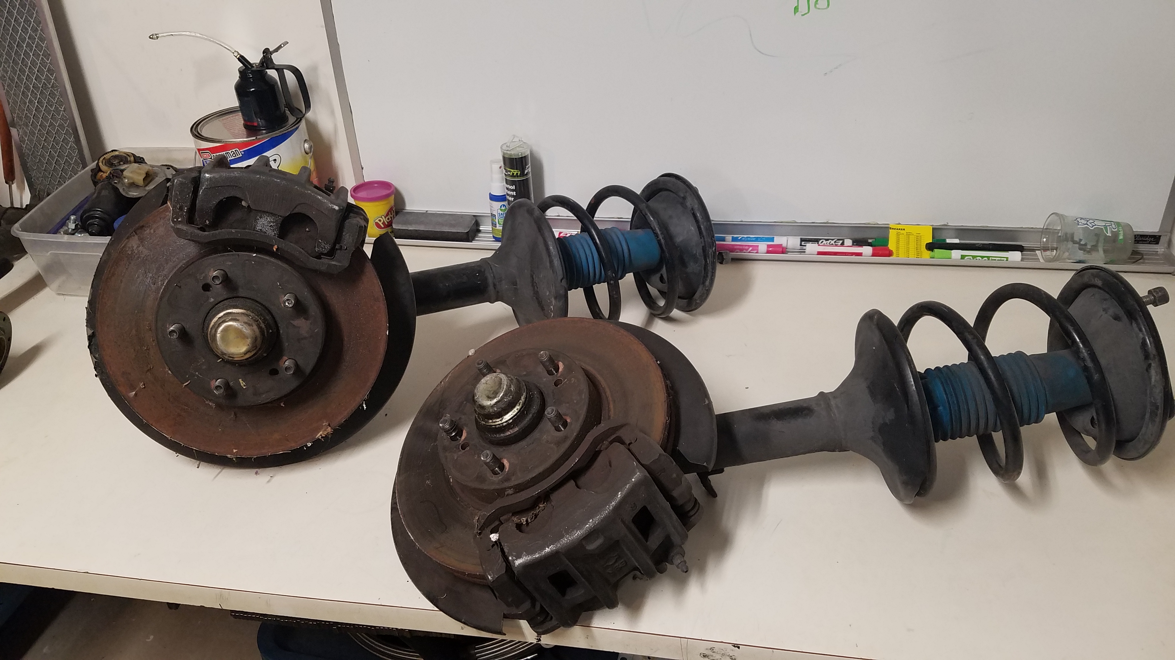
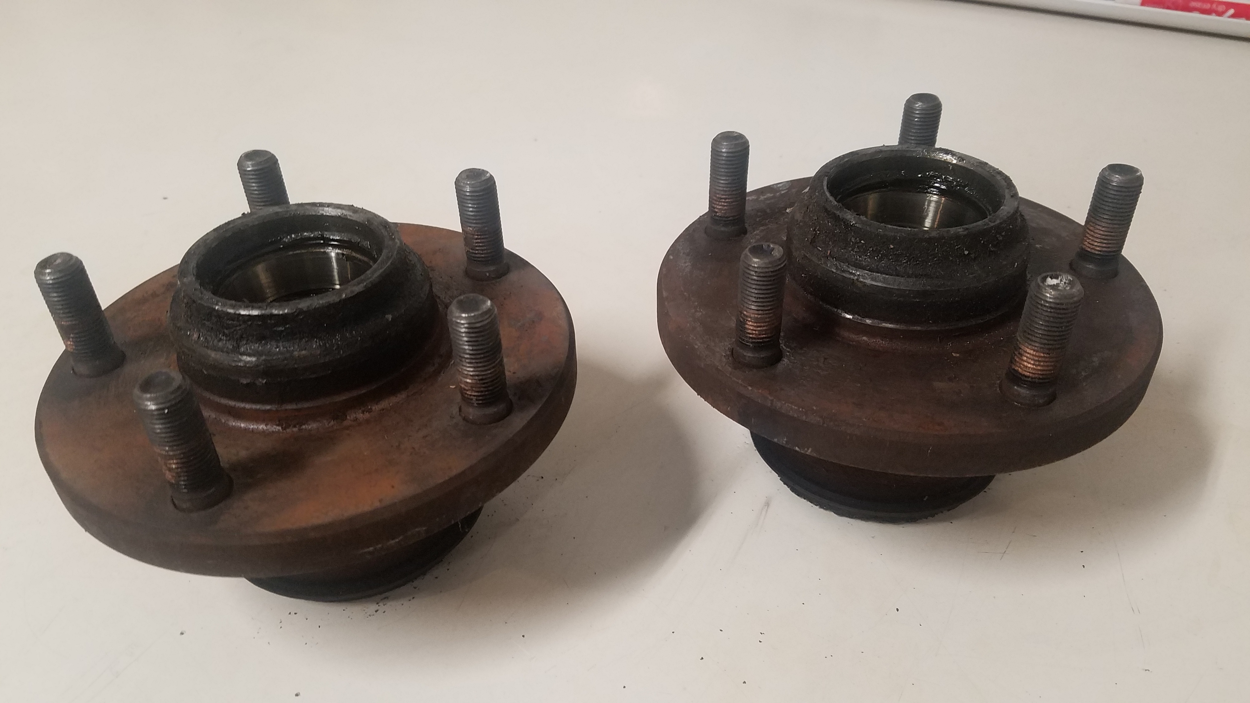
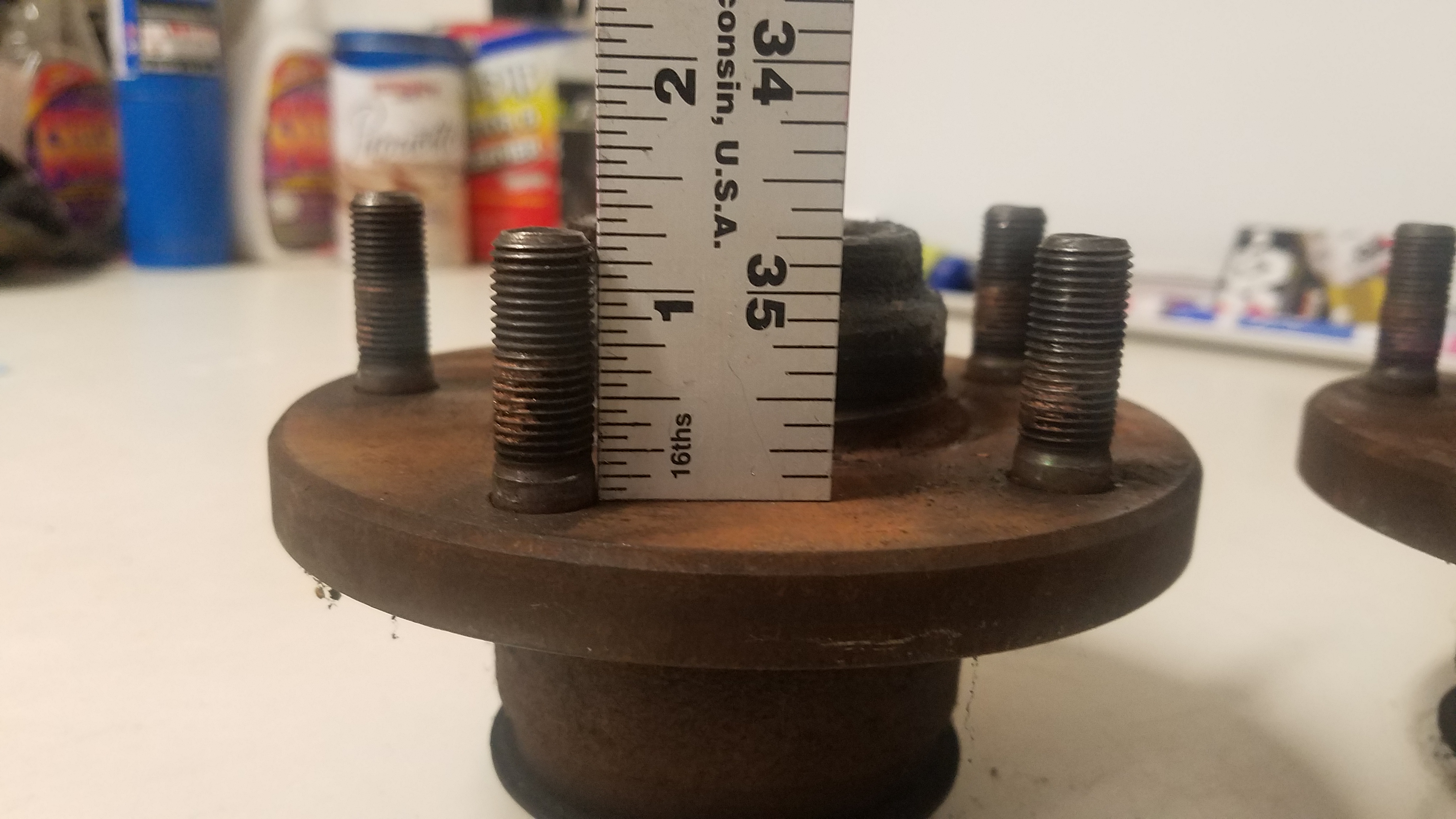
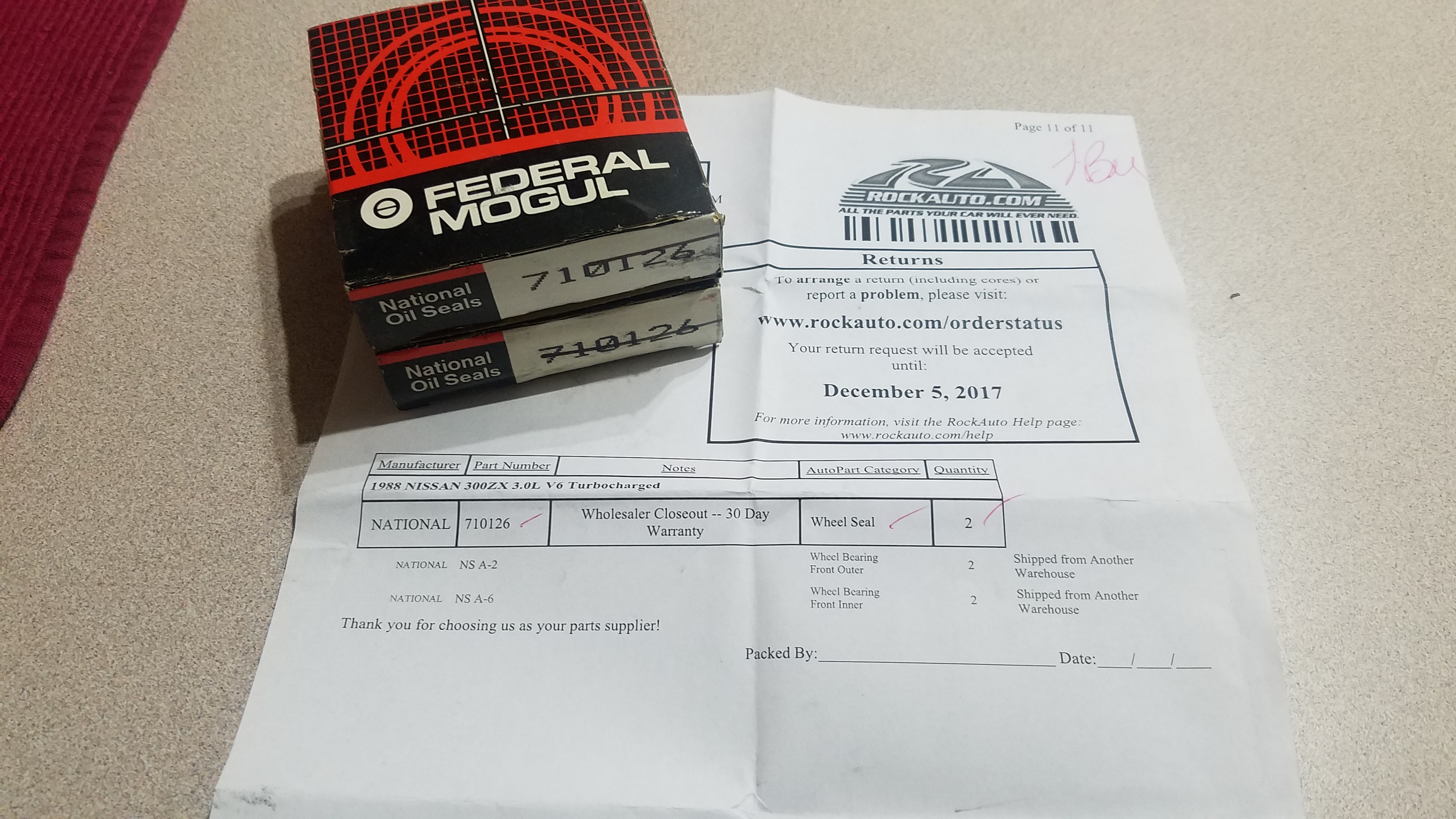
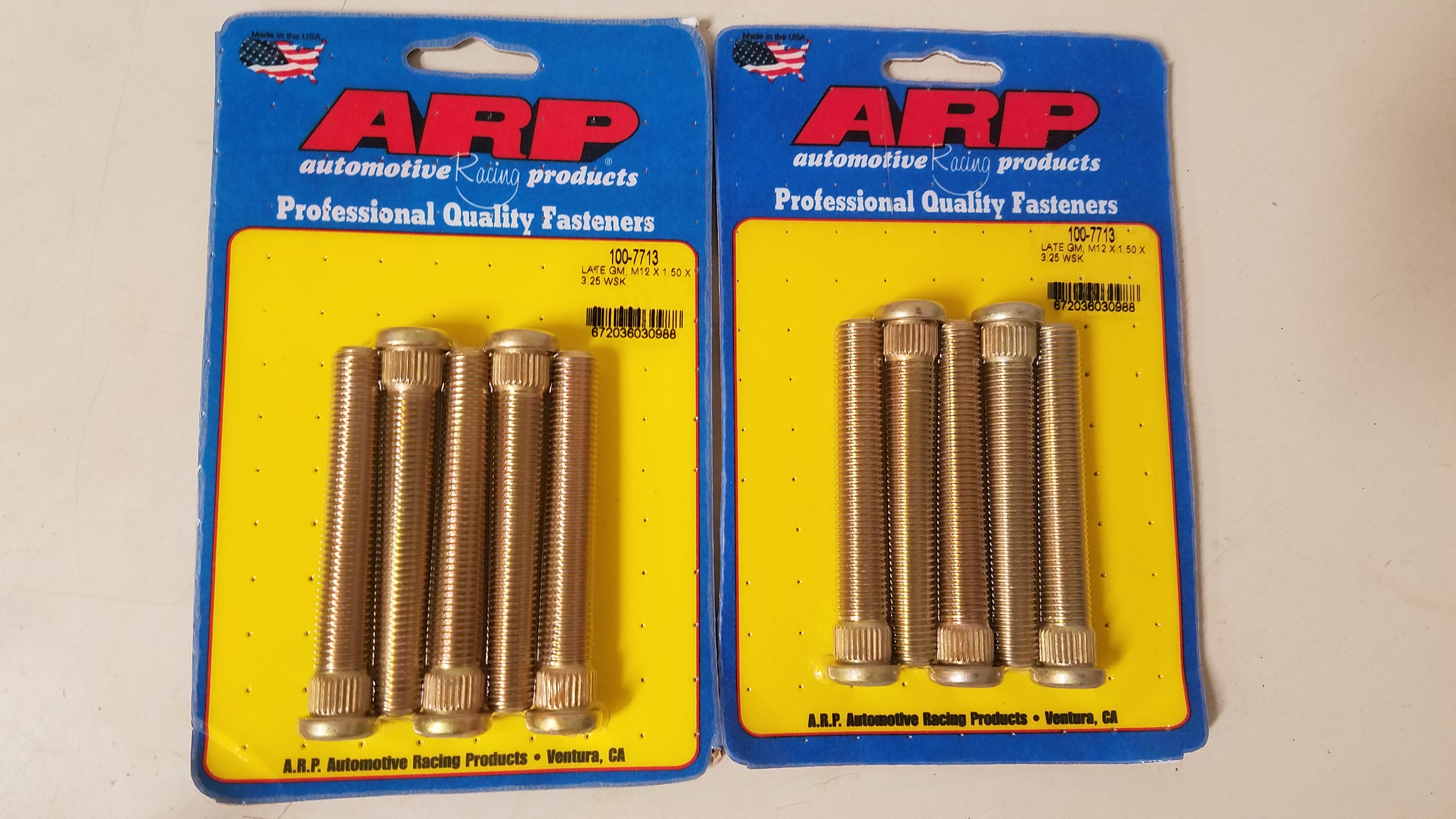
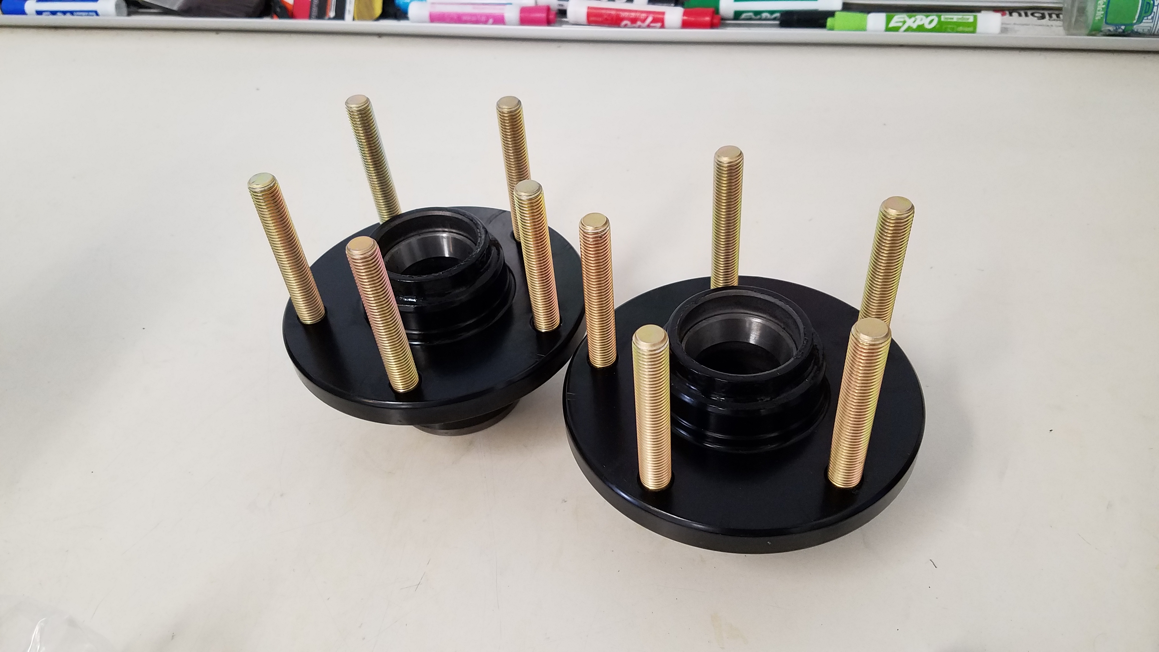
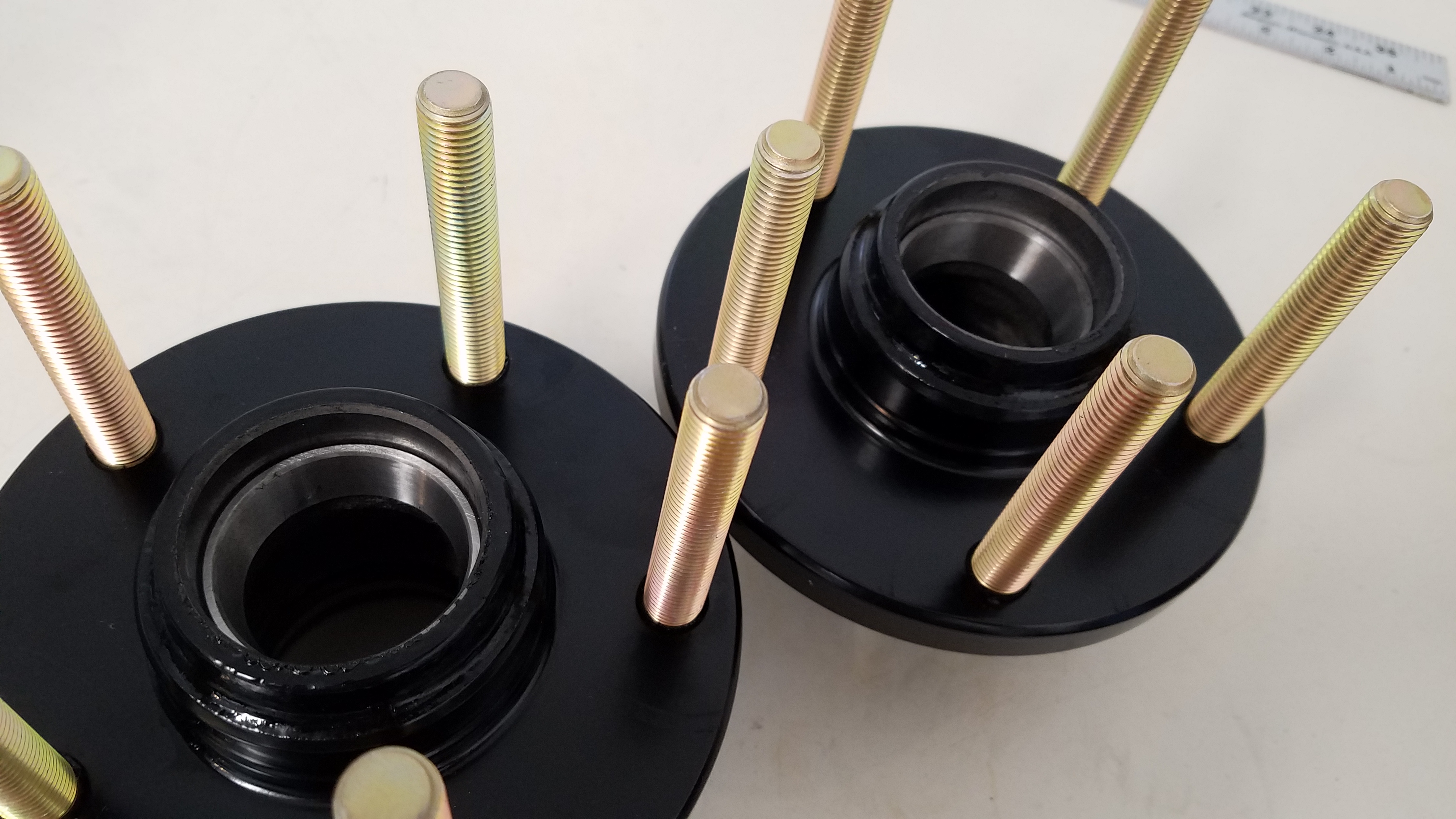
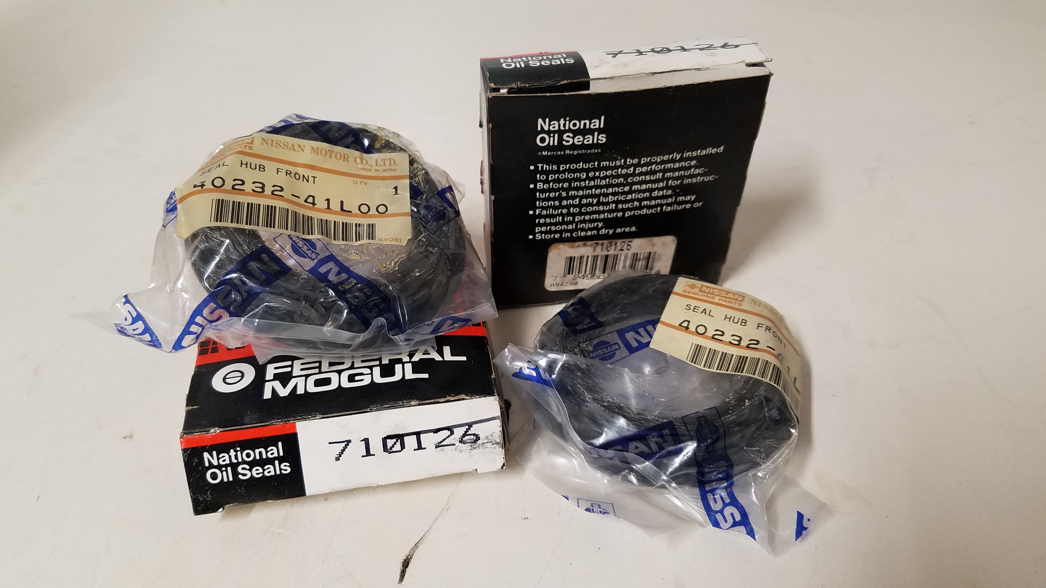
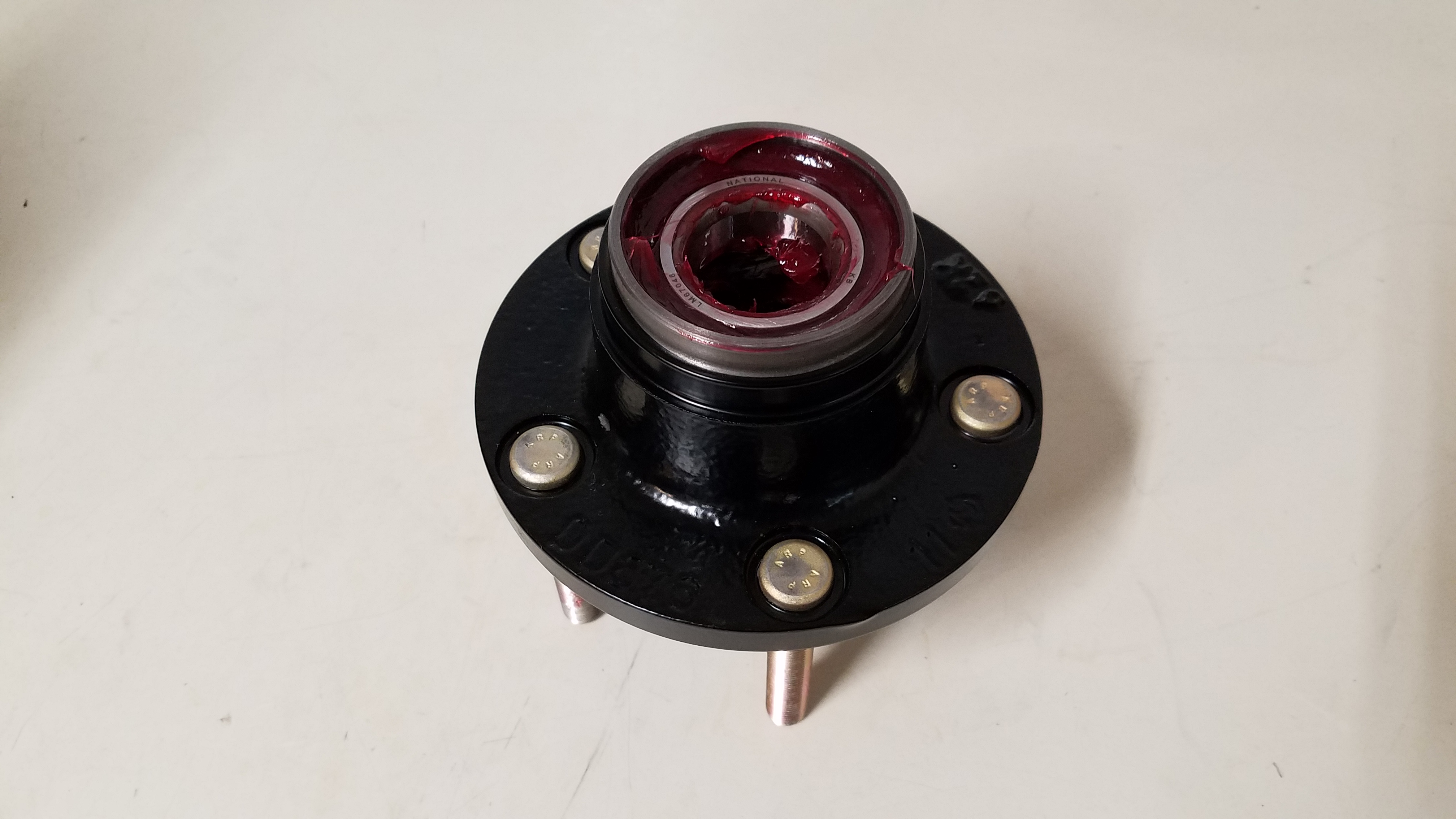
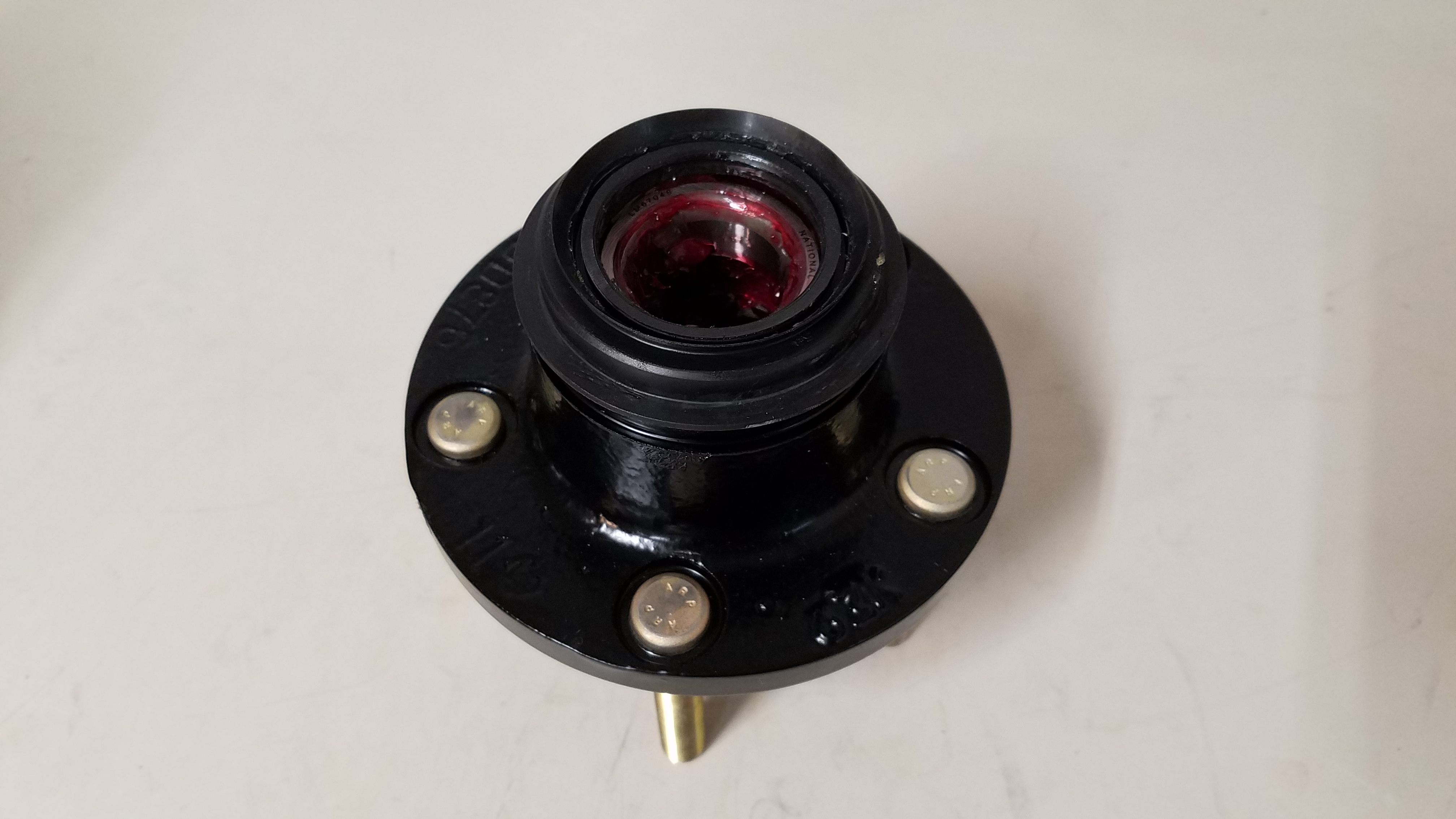
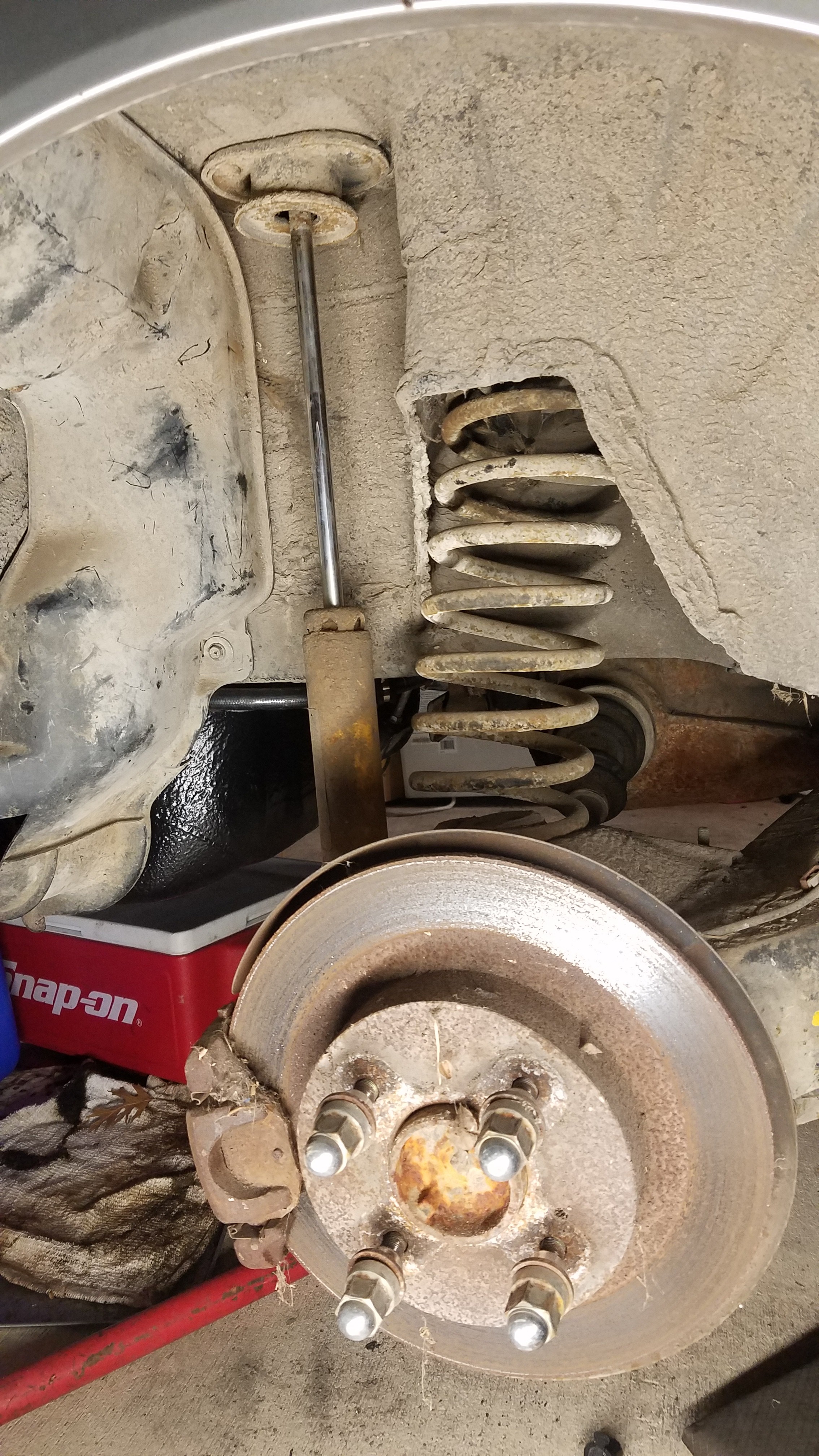
My brakes were next on the agenda. Both front calipers & 1 rear brake caliper had blown piston seals. The other rear caliper was completely locked up. I was wanting to convert to a slip style rotor. This style was available for late production 1987-1989 turbo Z31's. So the hunt for those front wheel hubs was on. The hunt came to a conclusion after 5 long months. With the purchase entire 88 turbo front strut pull offs for not even half going price of just the hubs. Which included calipers, worn rotors, hubs, brake dust shields, springs & bilstein shock inserts. The only parts I actually used was wheel hubs. Which had the wheel studs & bearing races quickly removed. Went ahead powder coated these too, like everything else I seem to touch (engage sarcasm). 3.25in long ARP wheel studs were pressed into the hubs. (Part # 100-7713) followed by new bearings & races. Then I received a suprise when the replacement wheel bearing seals. I ordered nationals on rockauto. Enclosed in the national box was NOS factory seals. Honestly I shouldn't be too surprised, considering Natoinal was the OEM supplier. The wheel hubs were now complete with the wheel bearing seals installed.
-
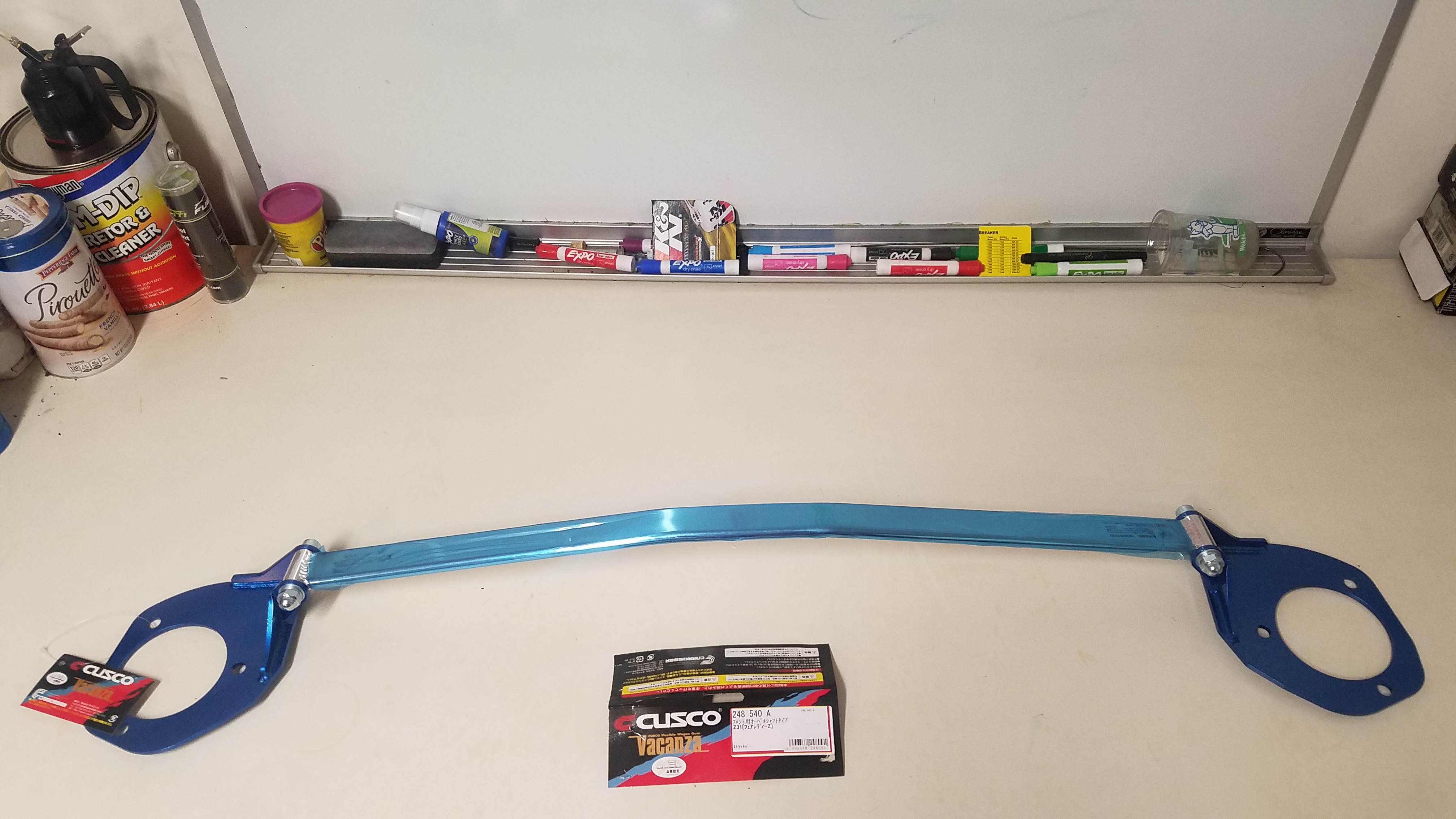
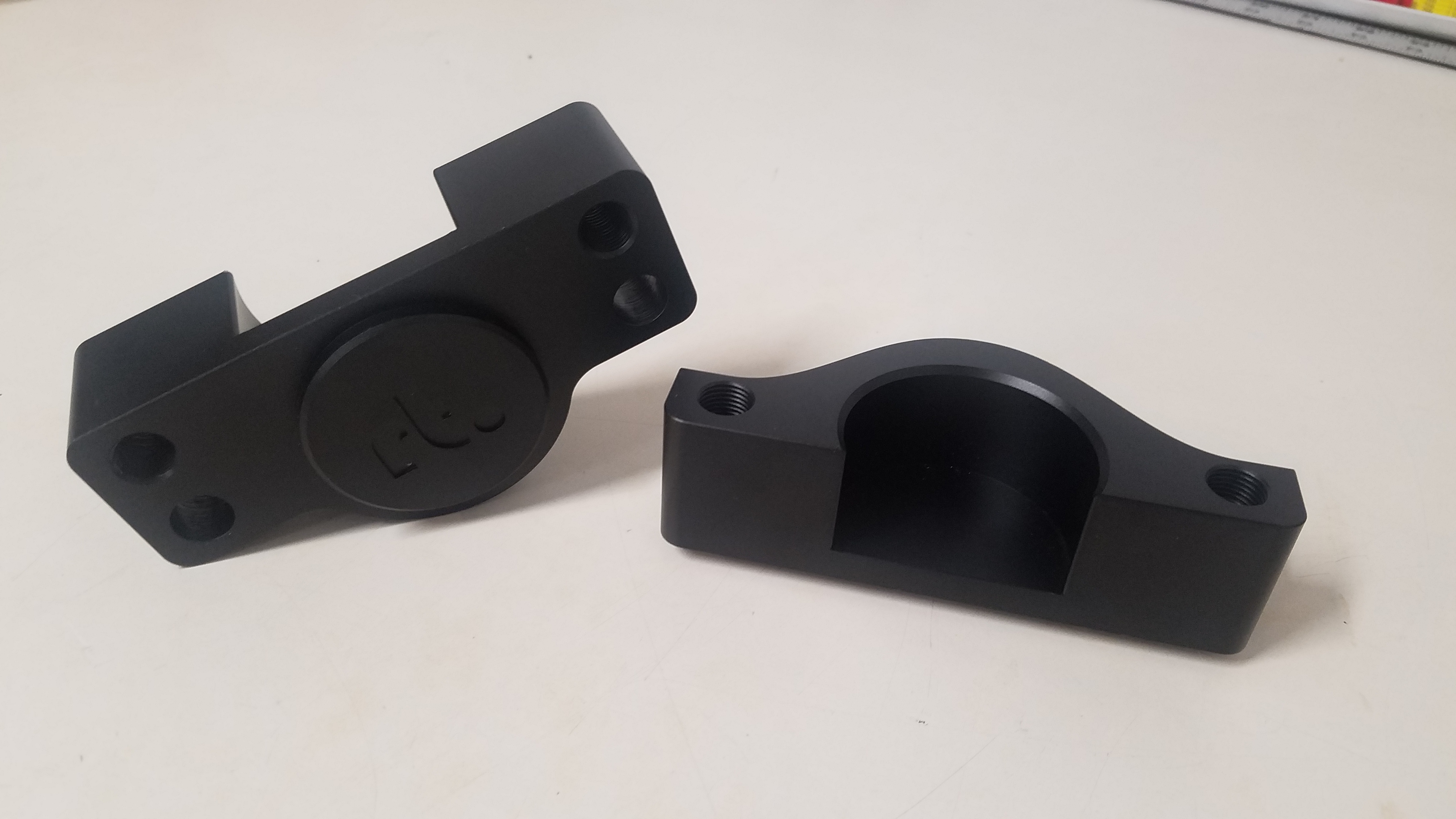
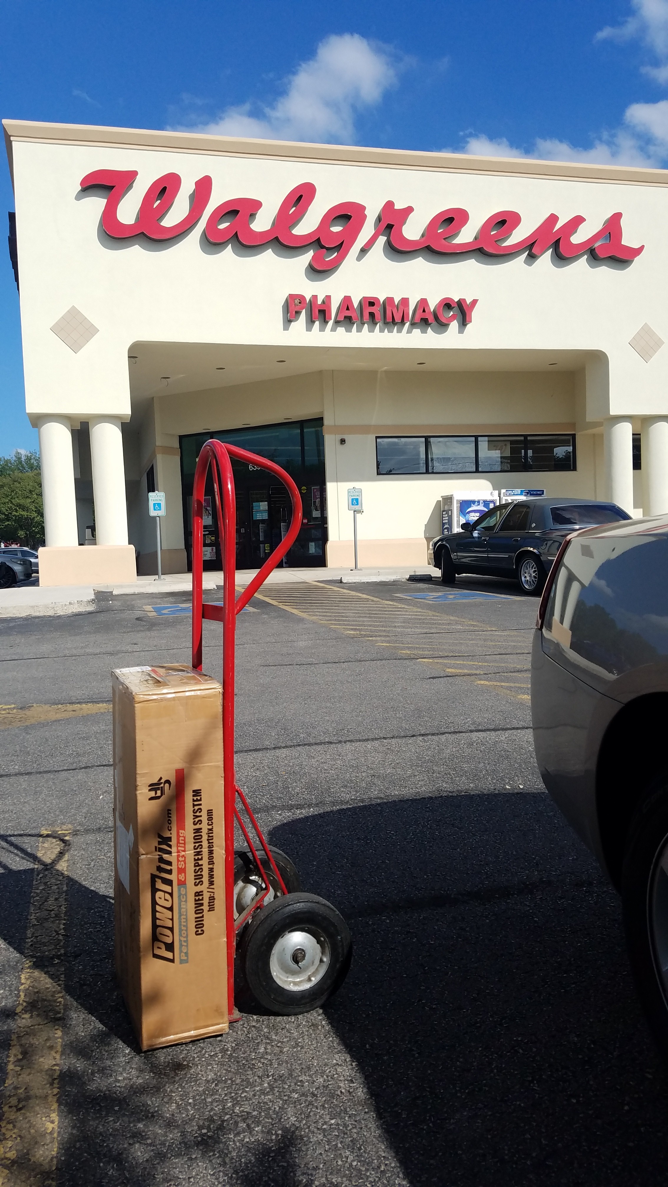
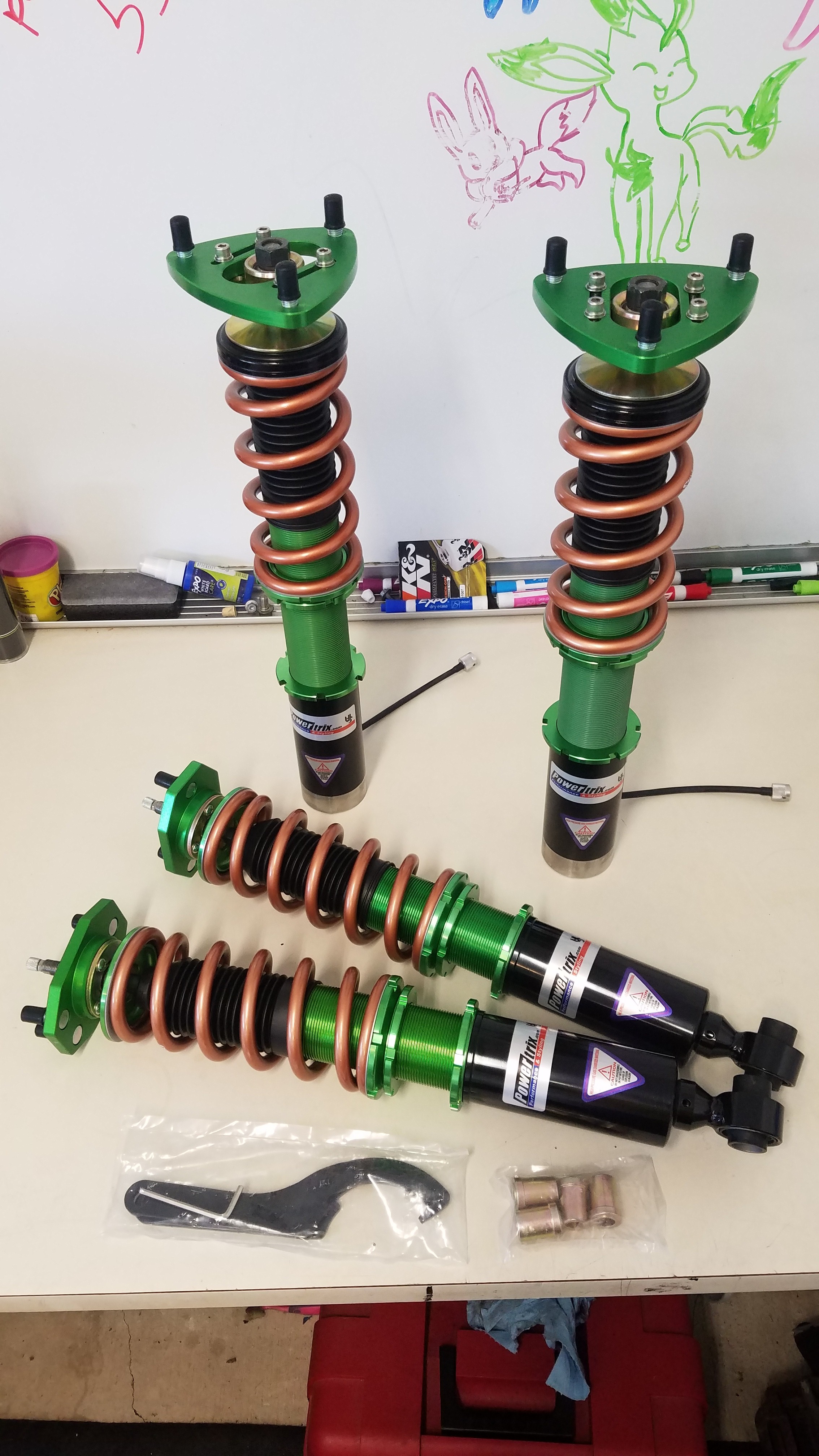
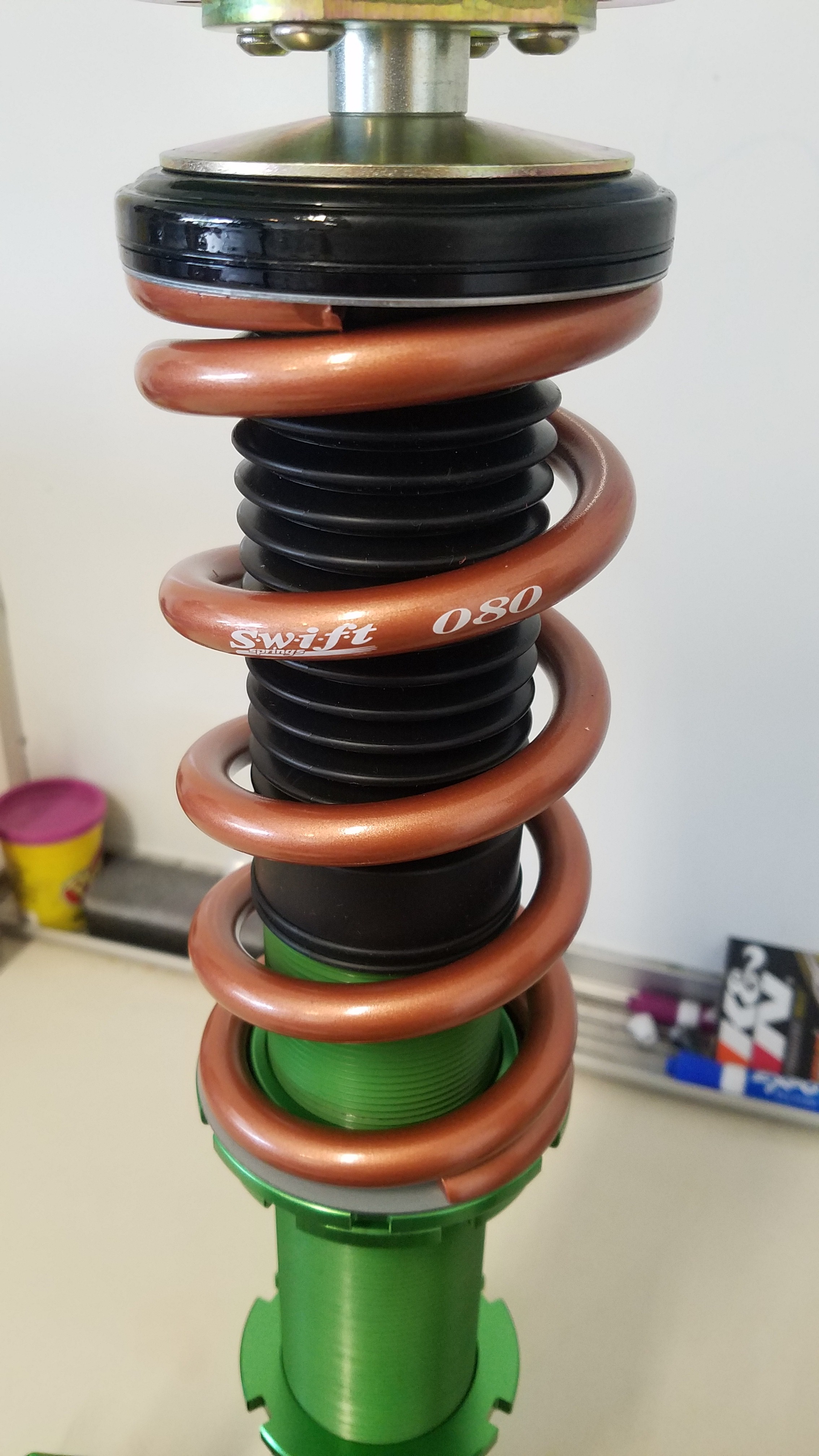
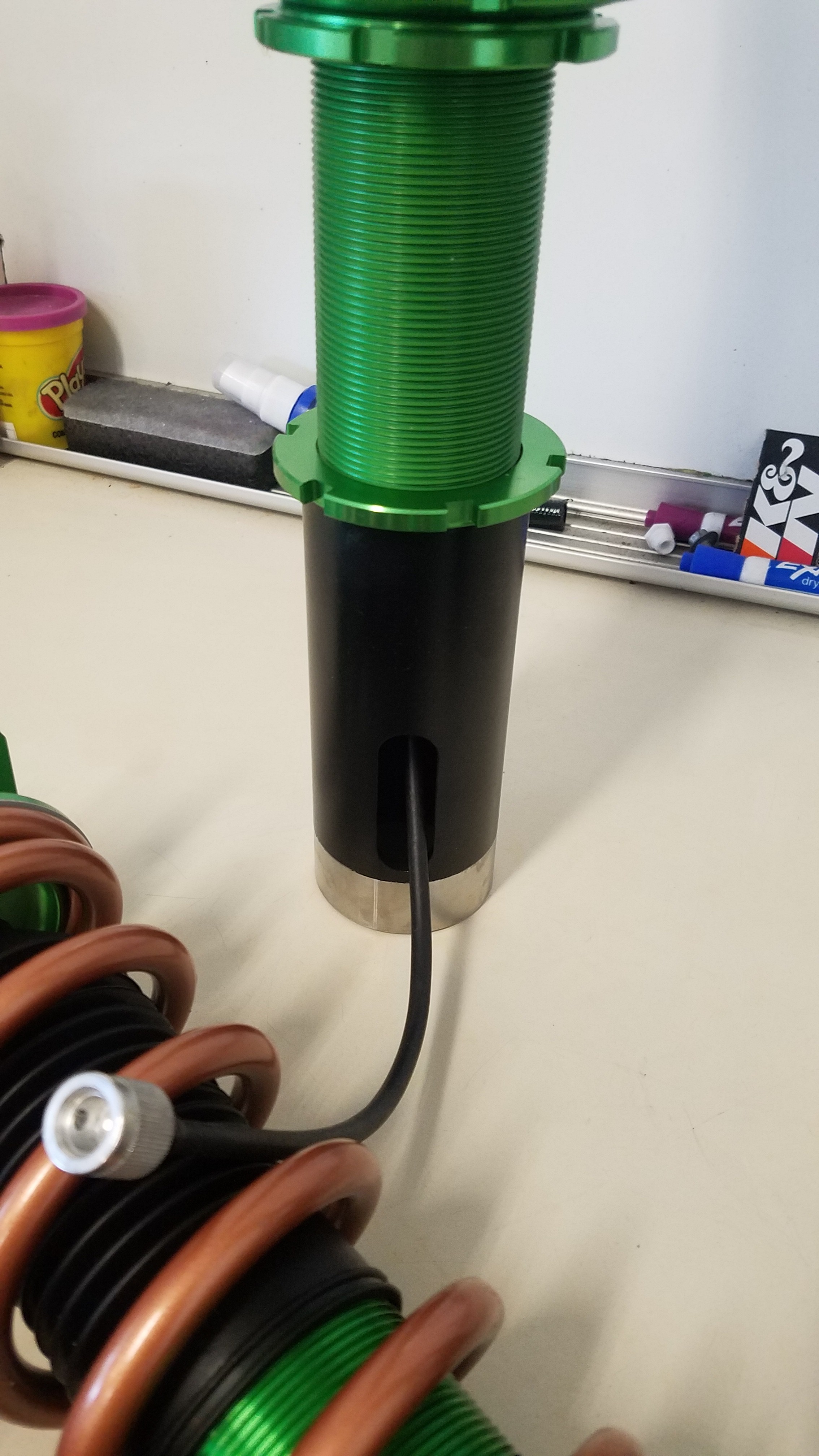
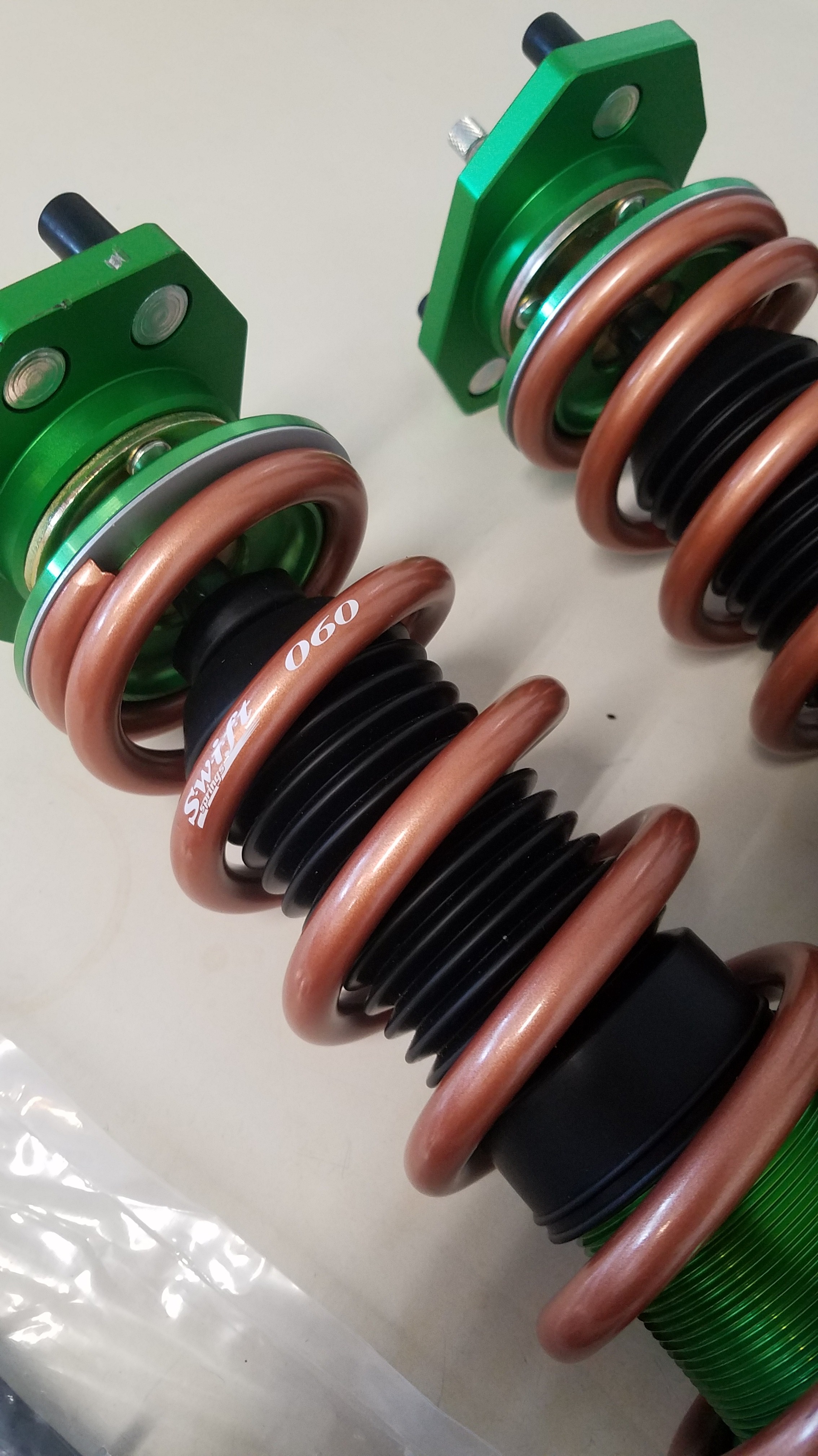
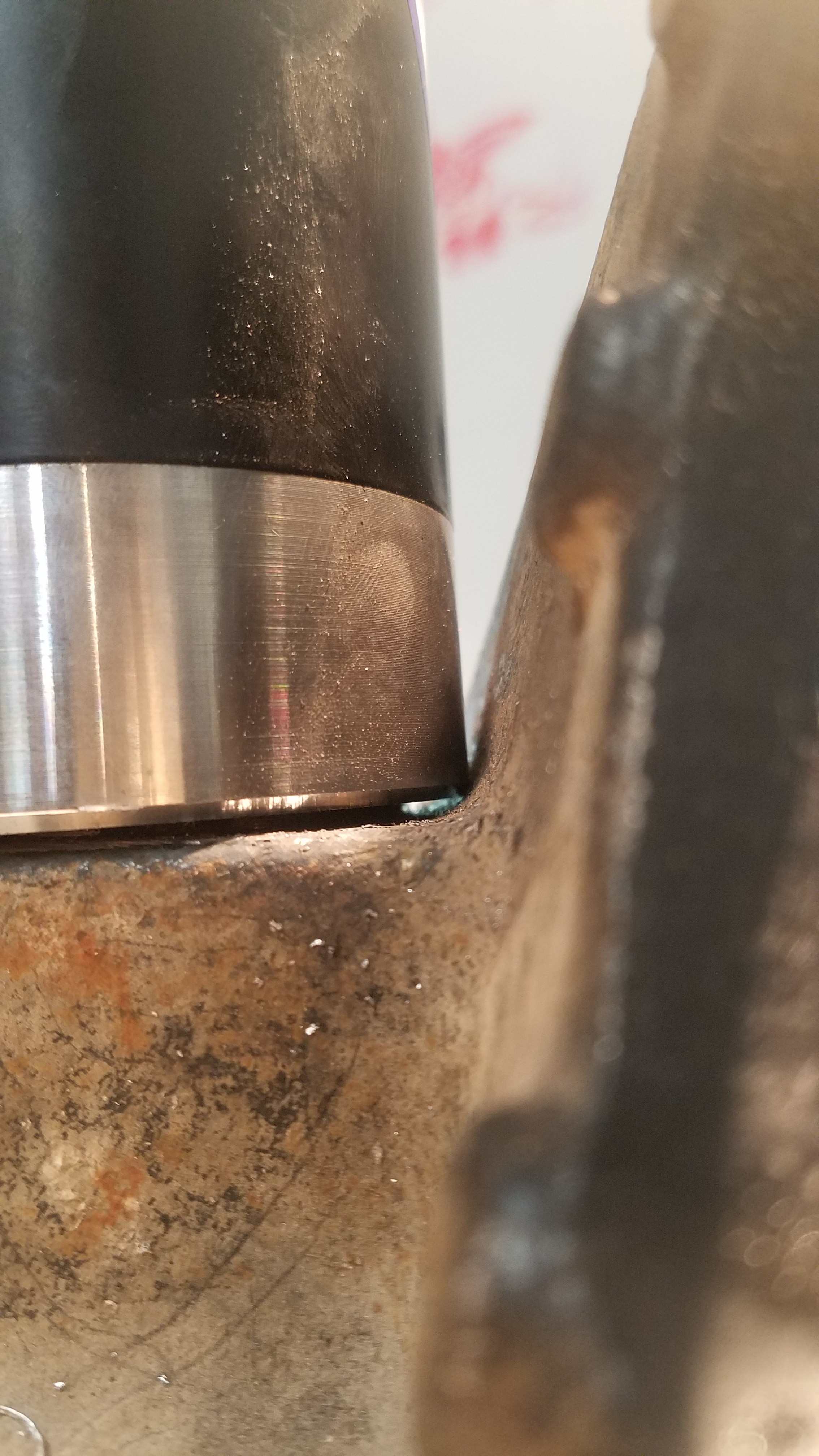
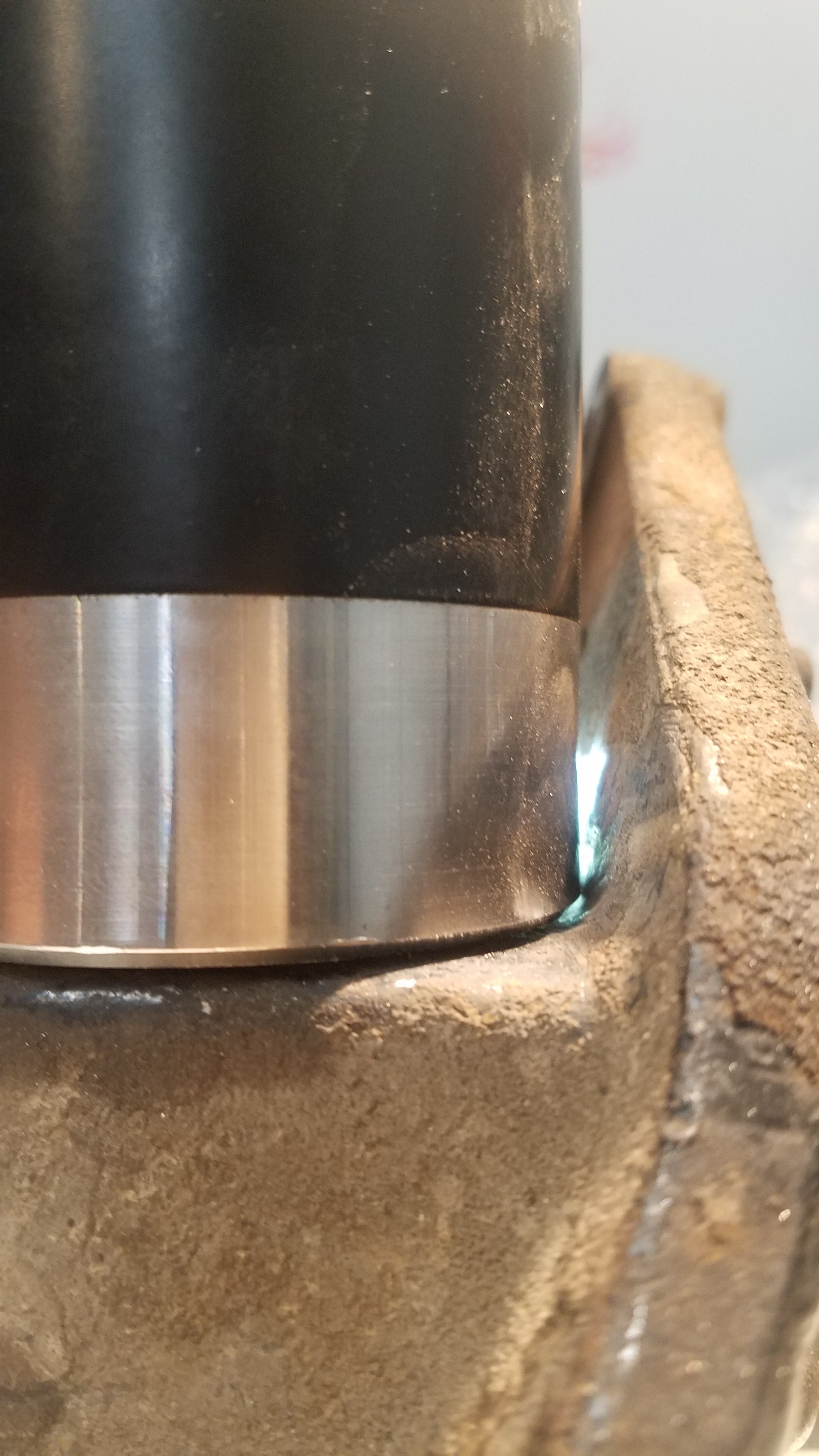
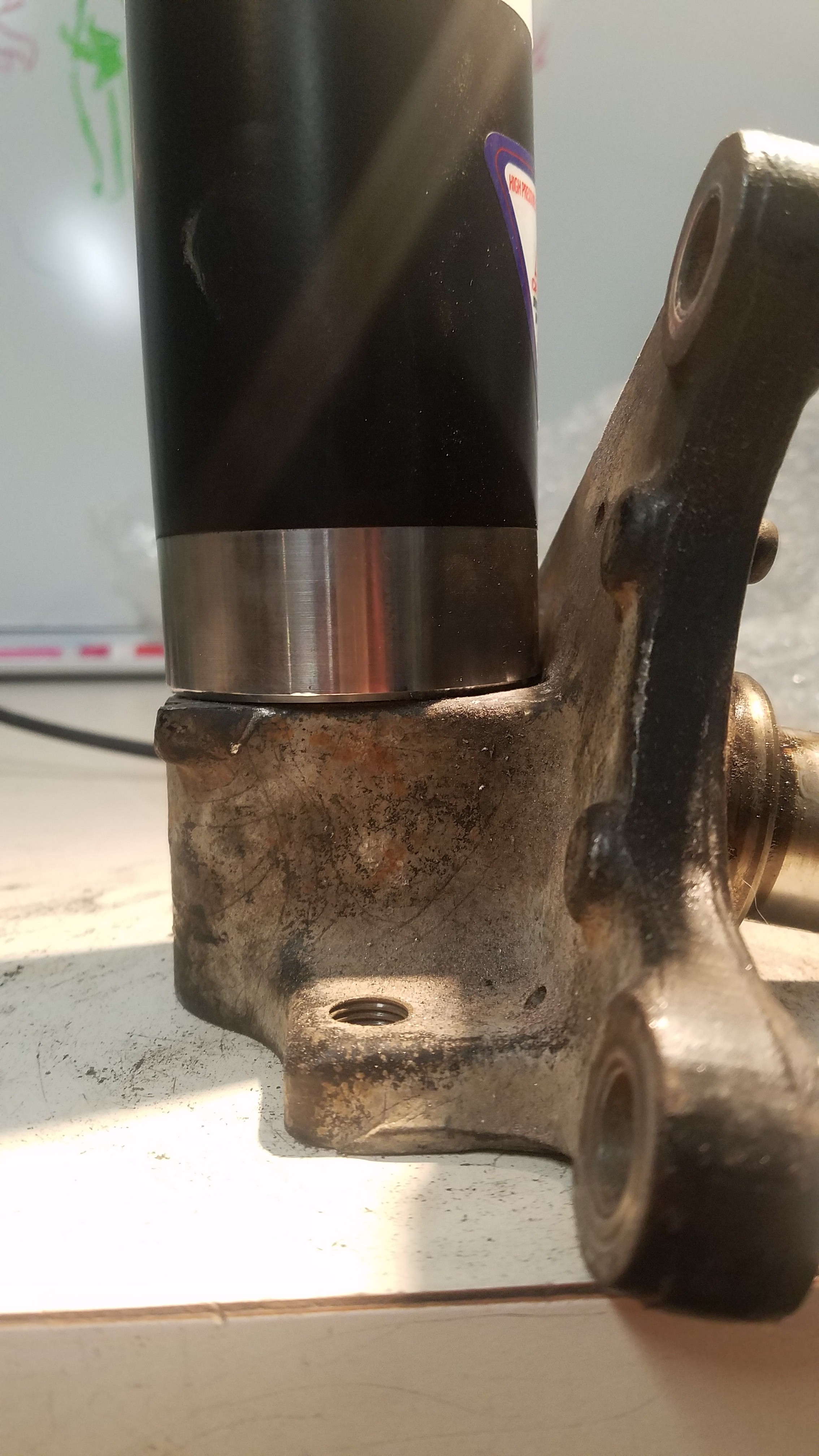
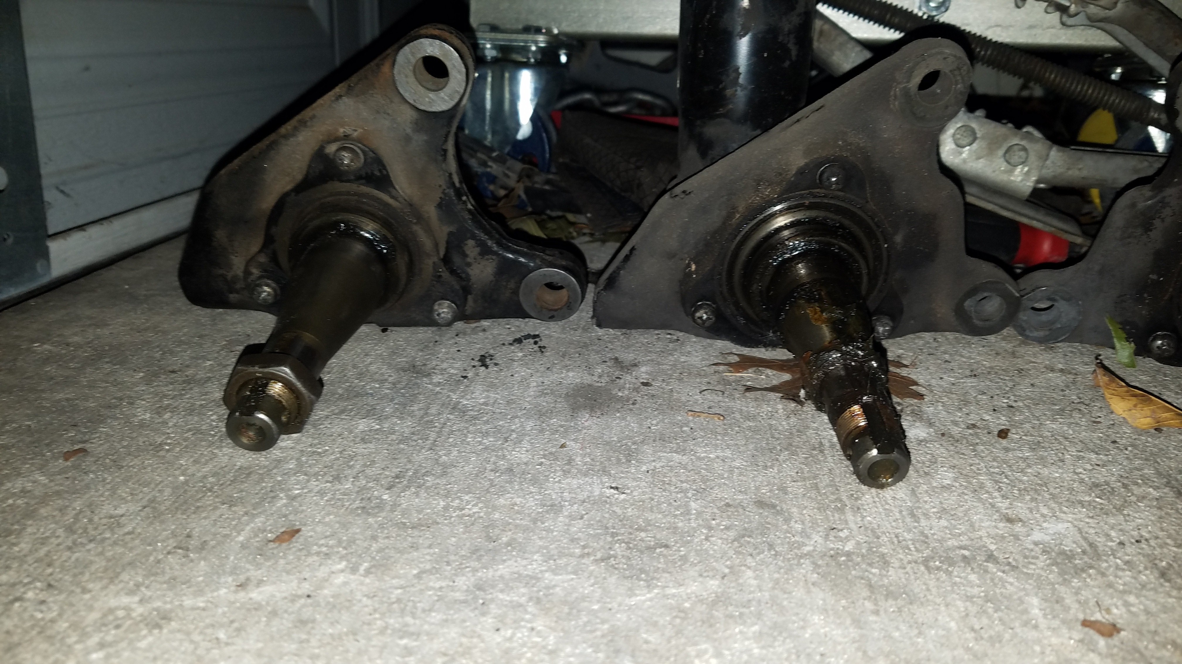
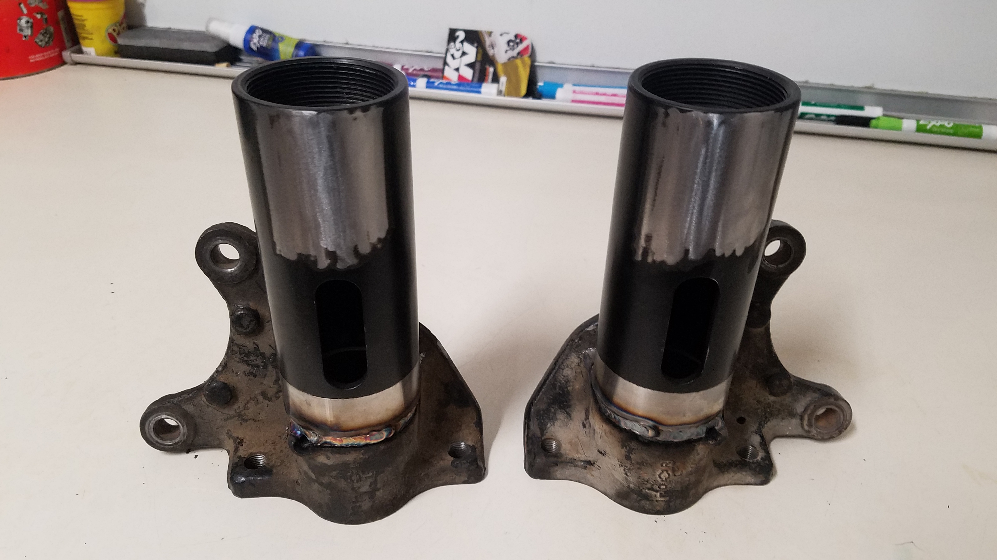
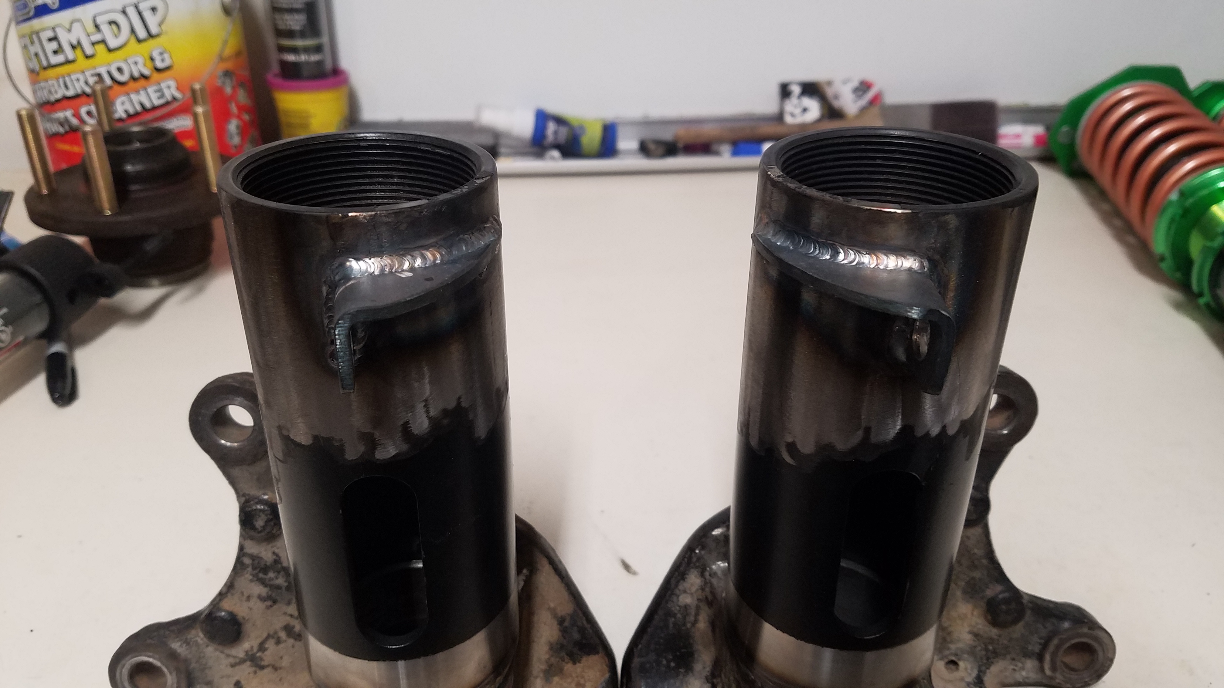
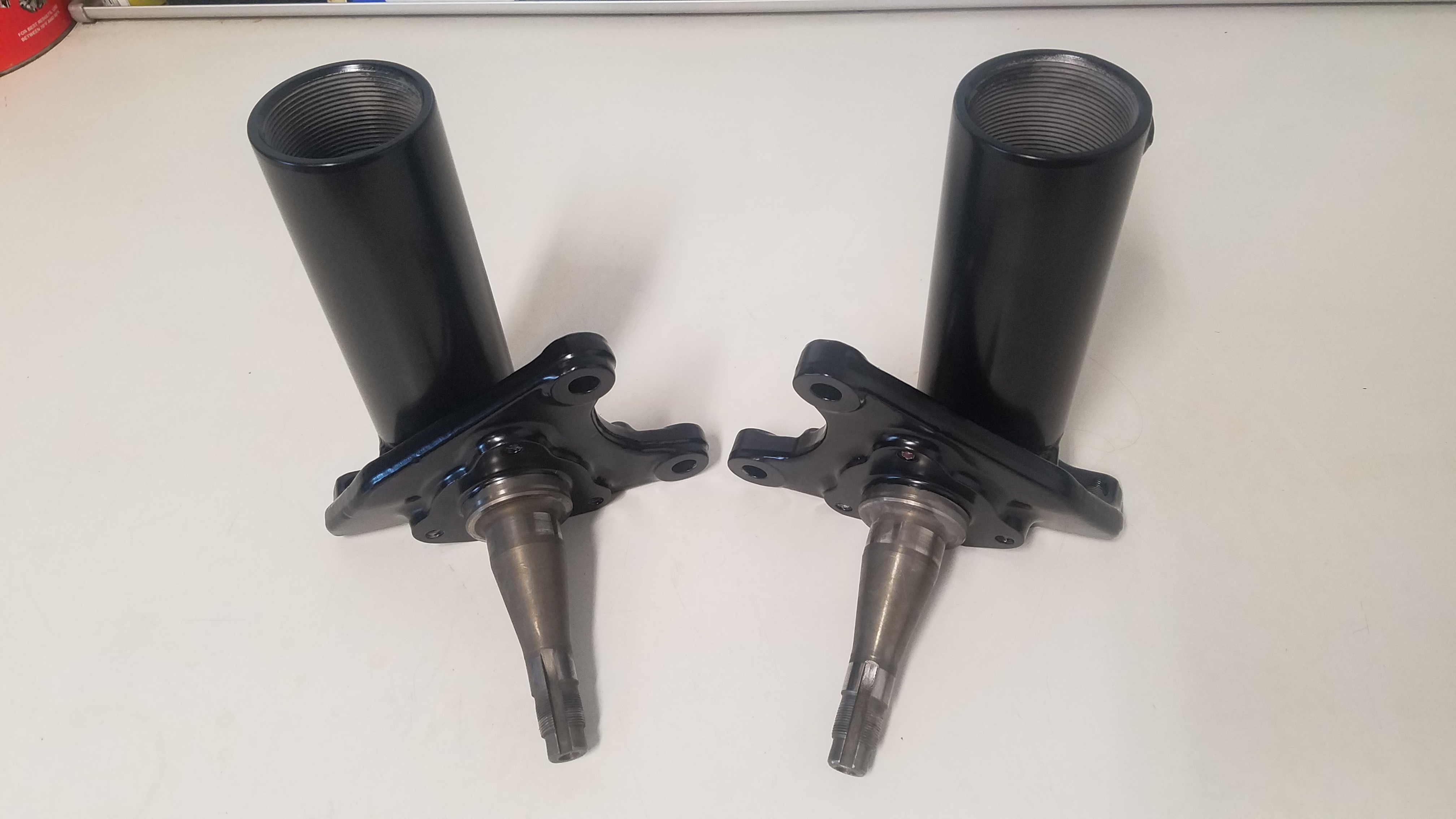
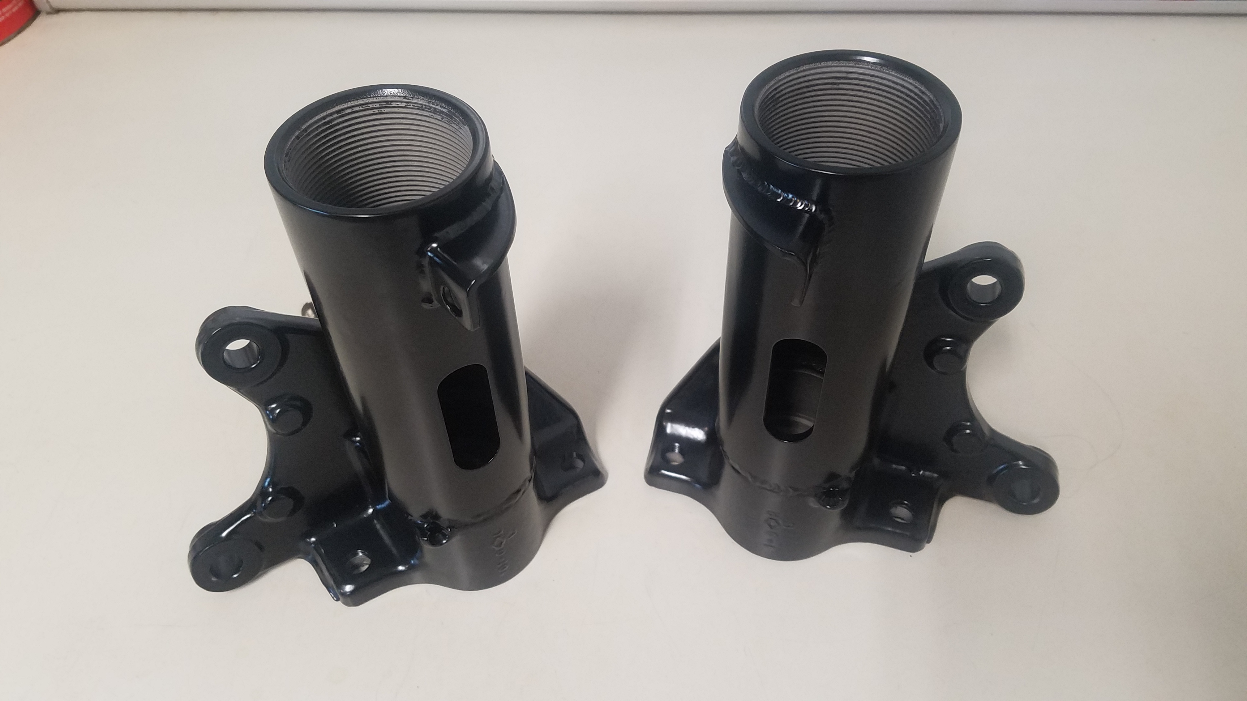
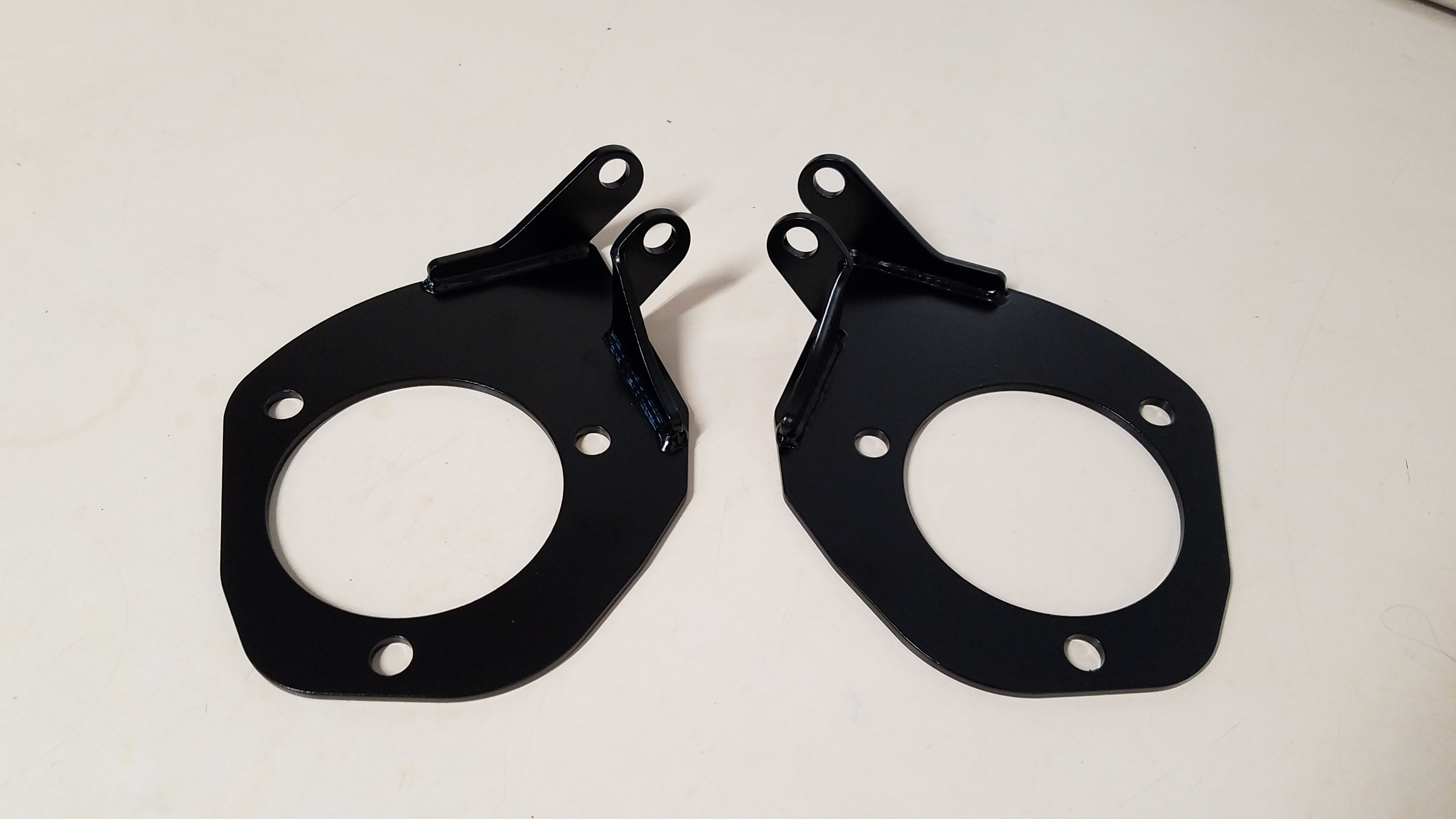
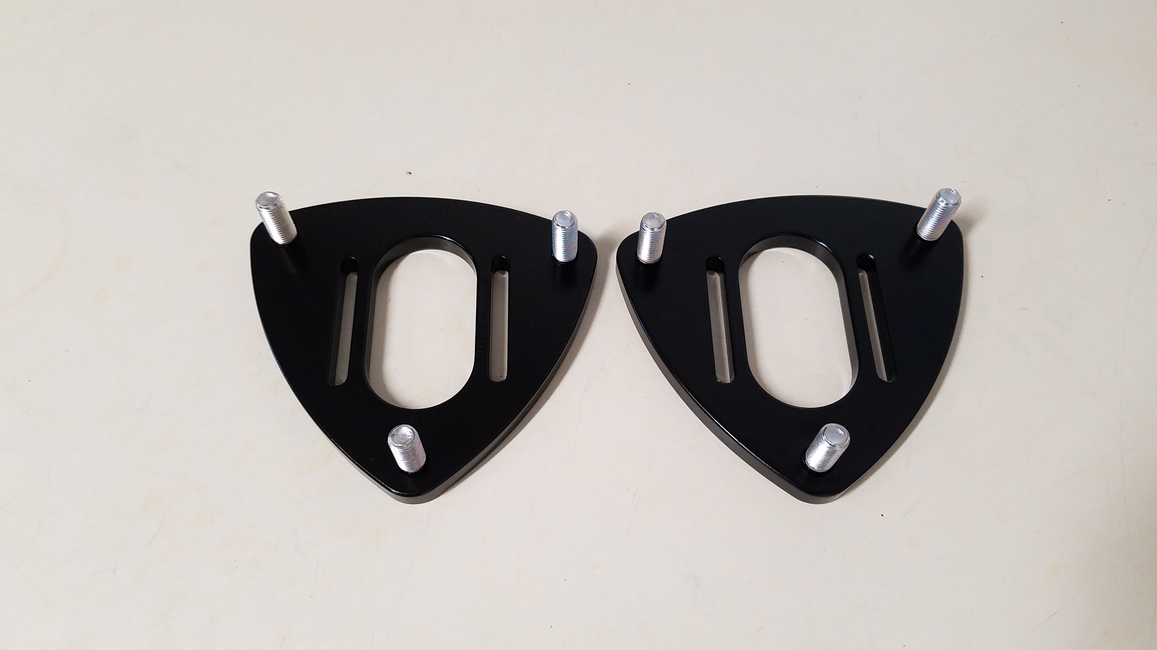
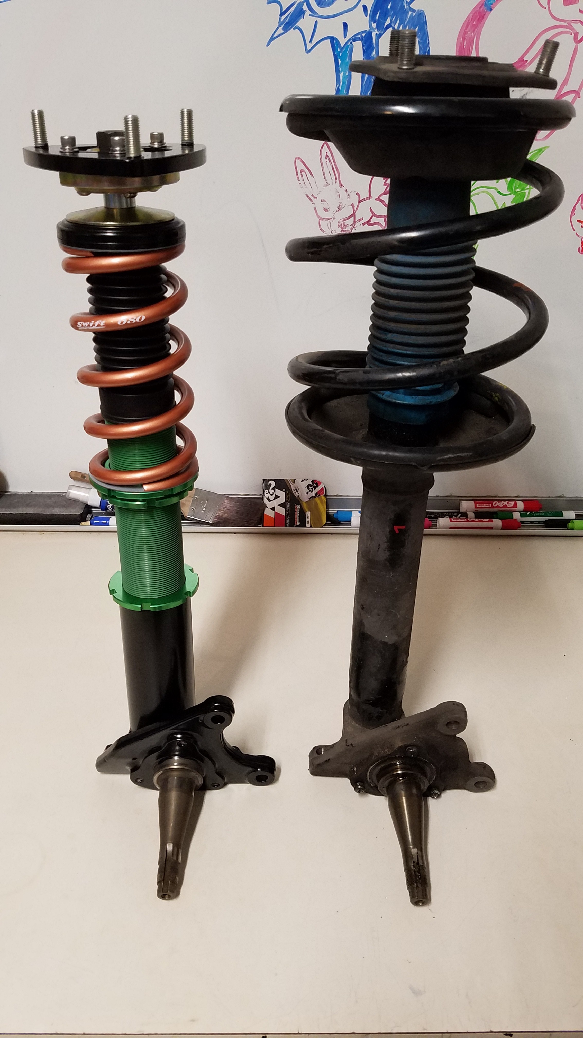
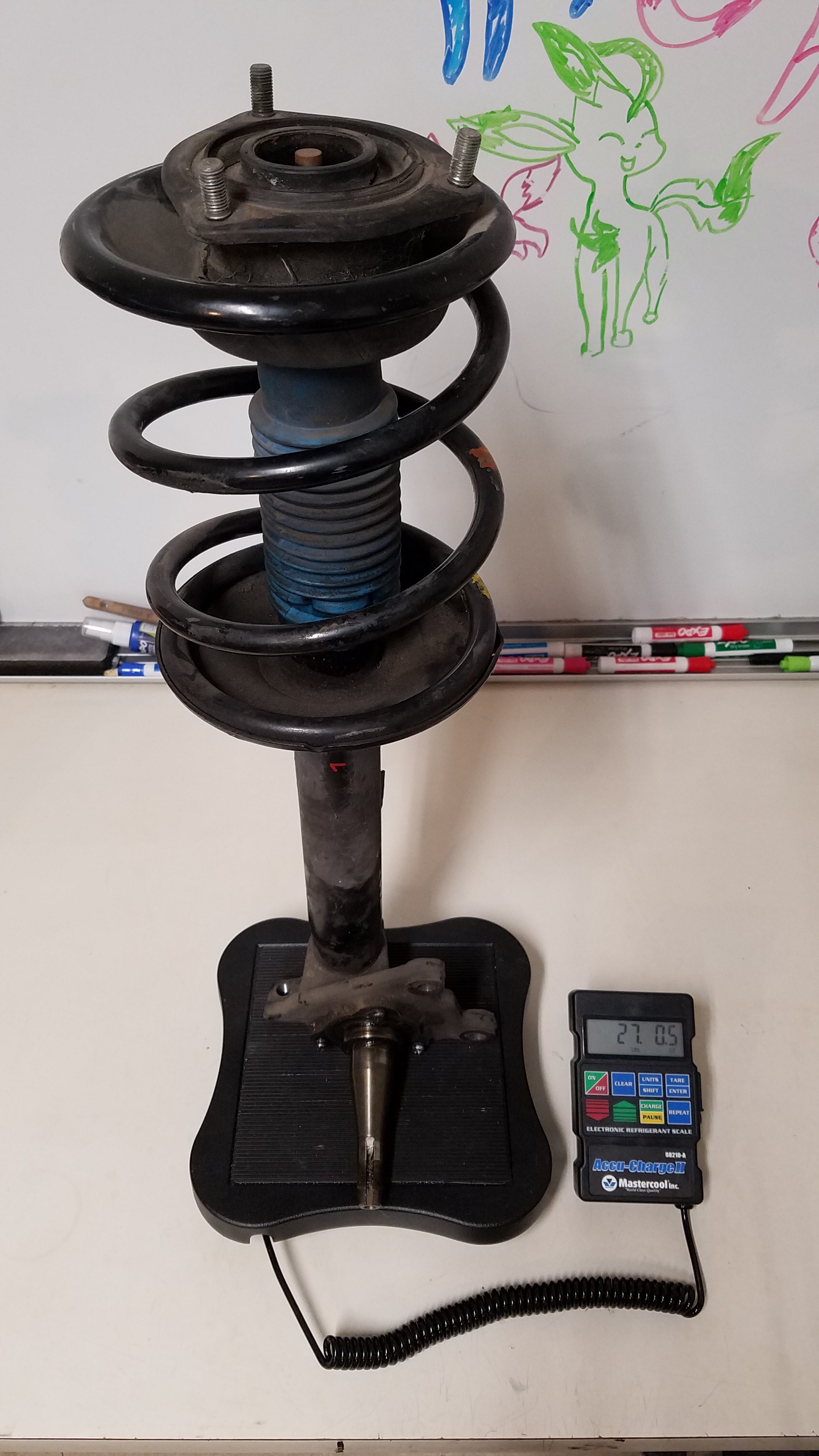
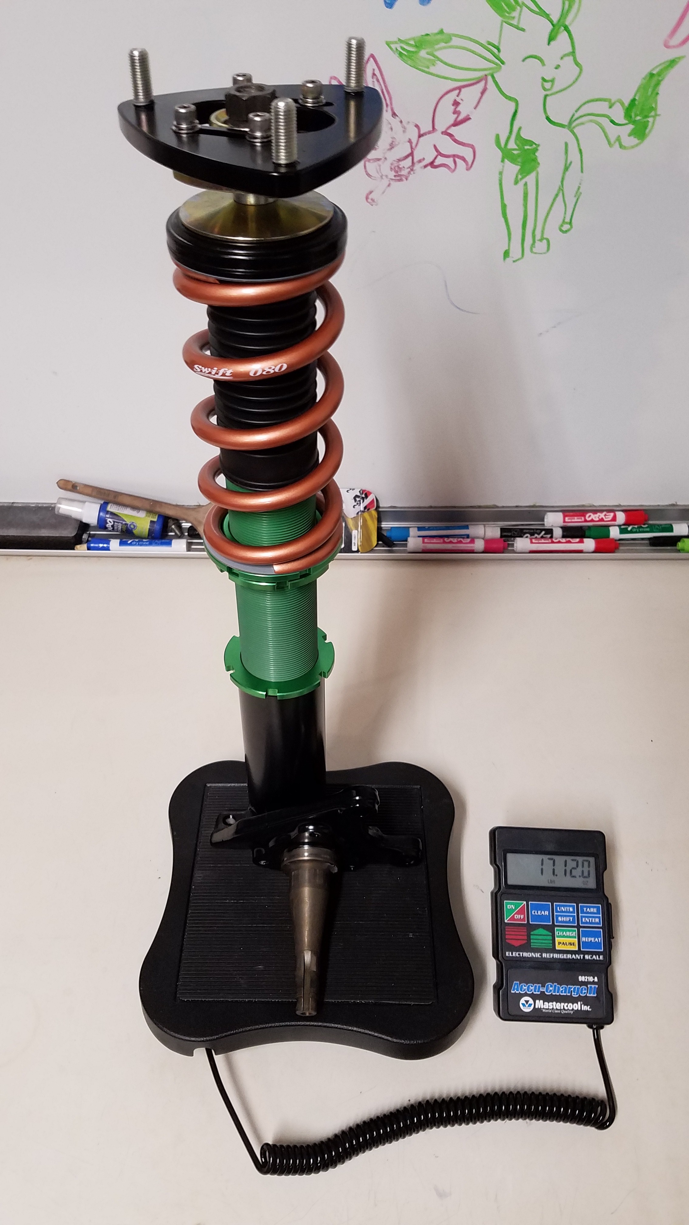
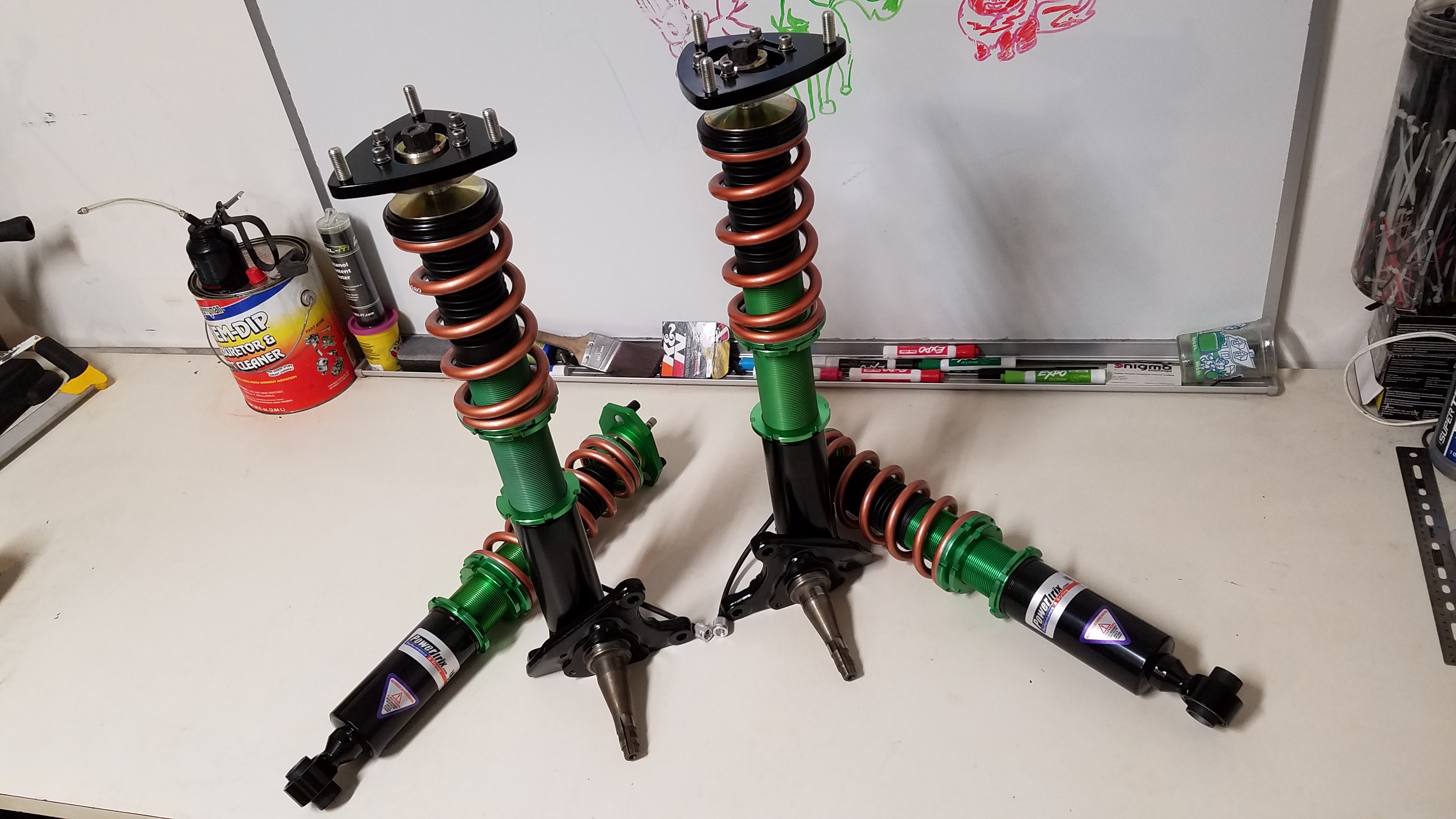
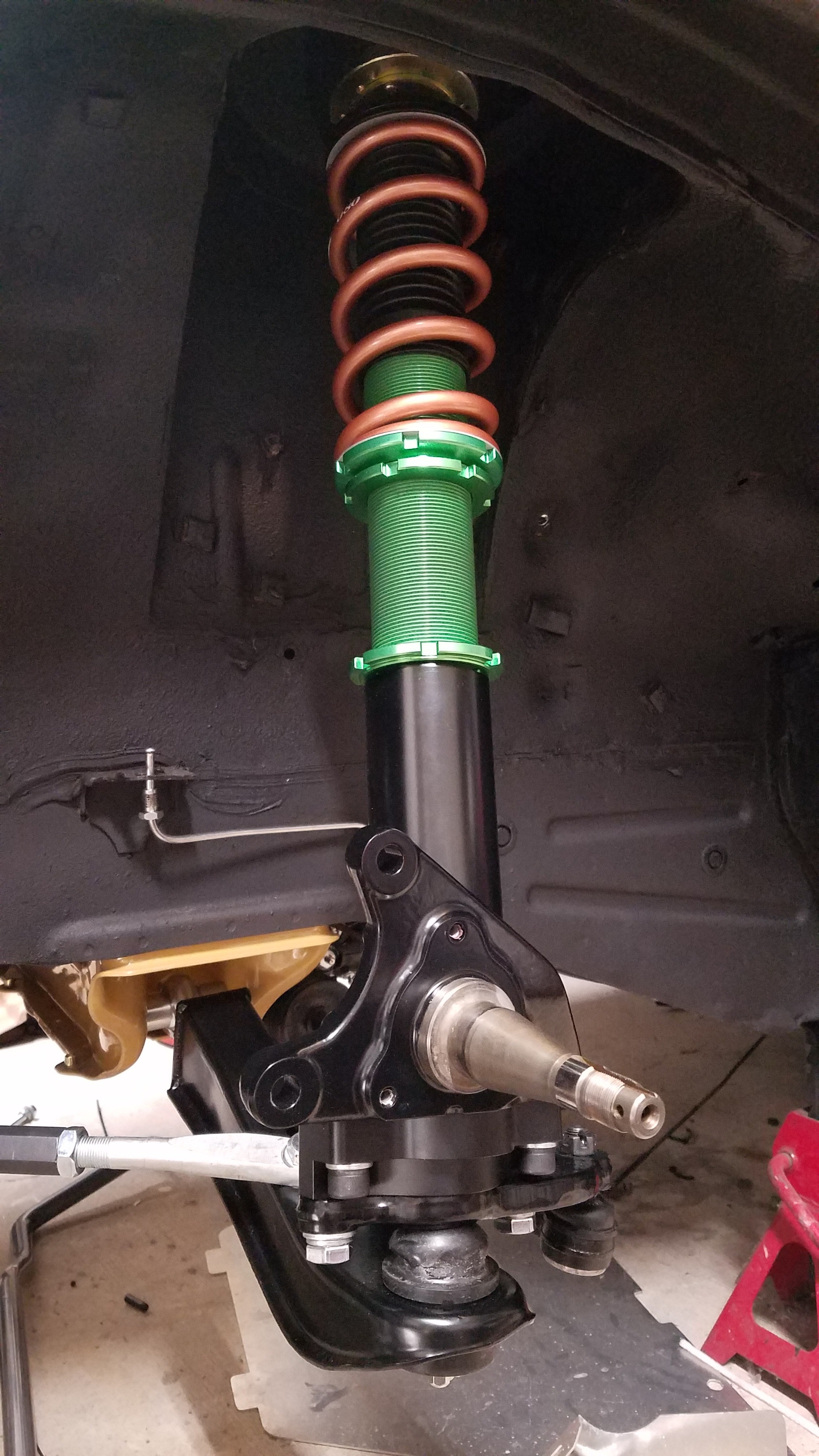
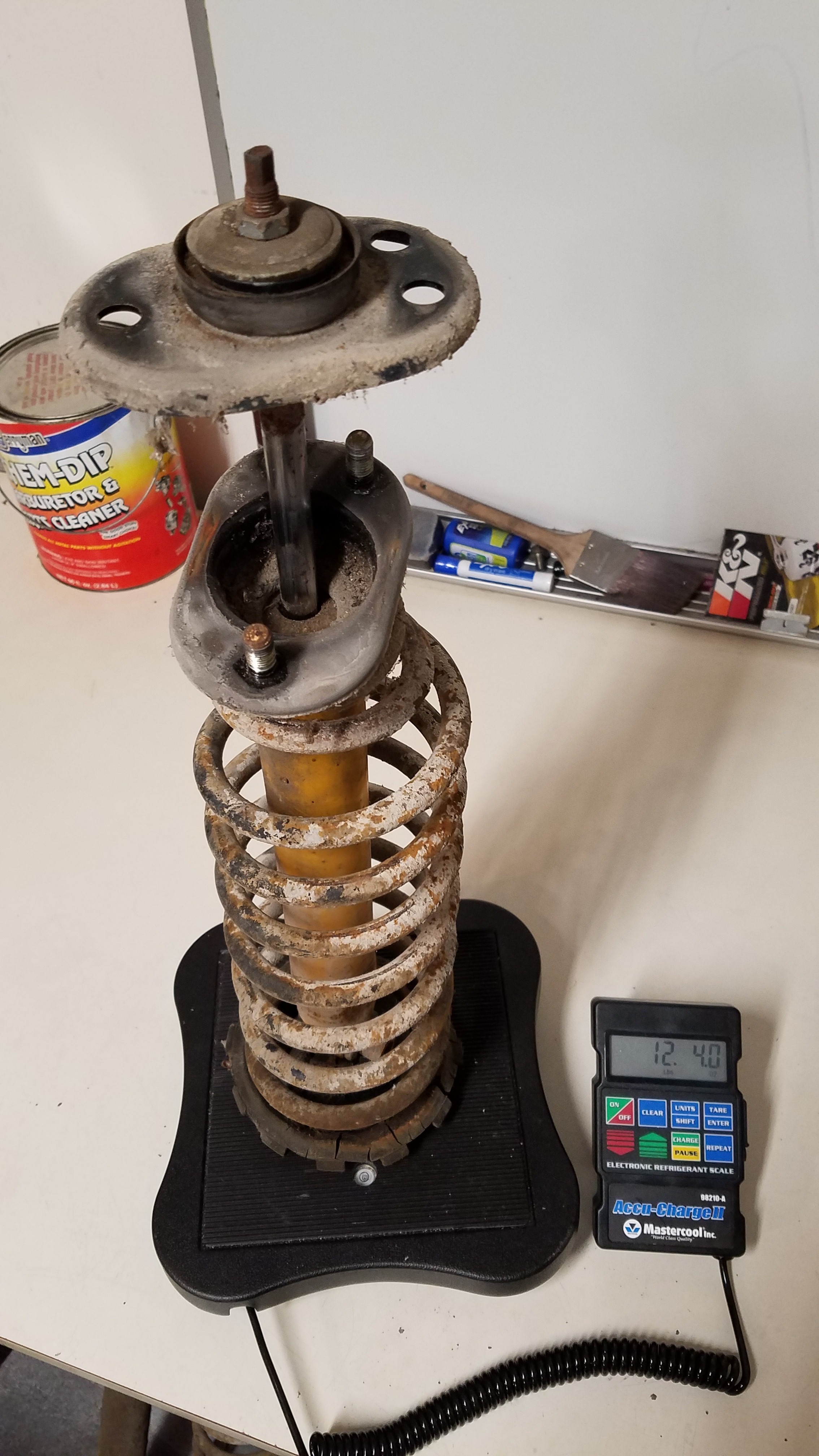
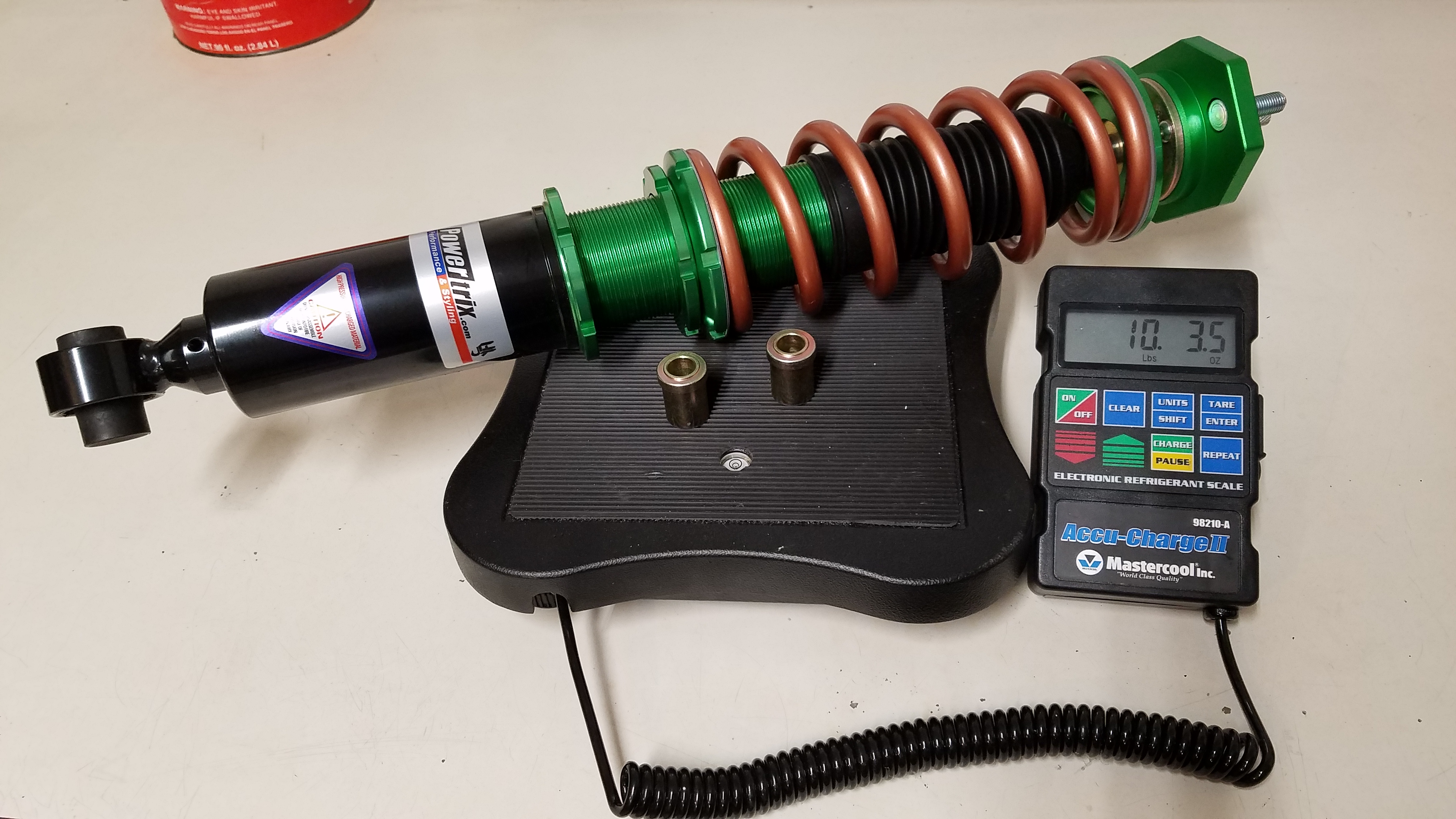
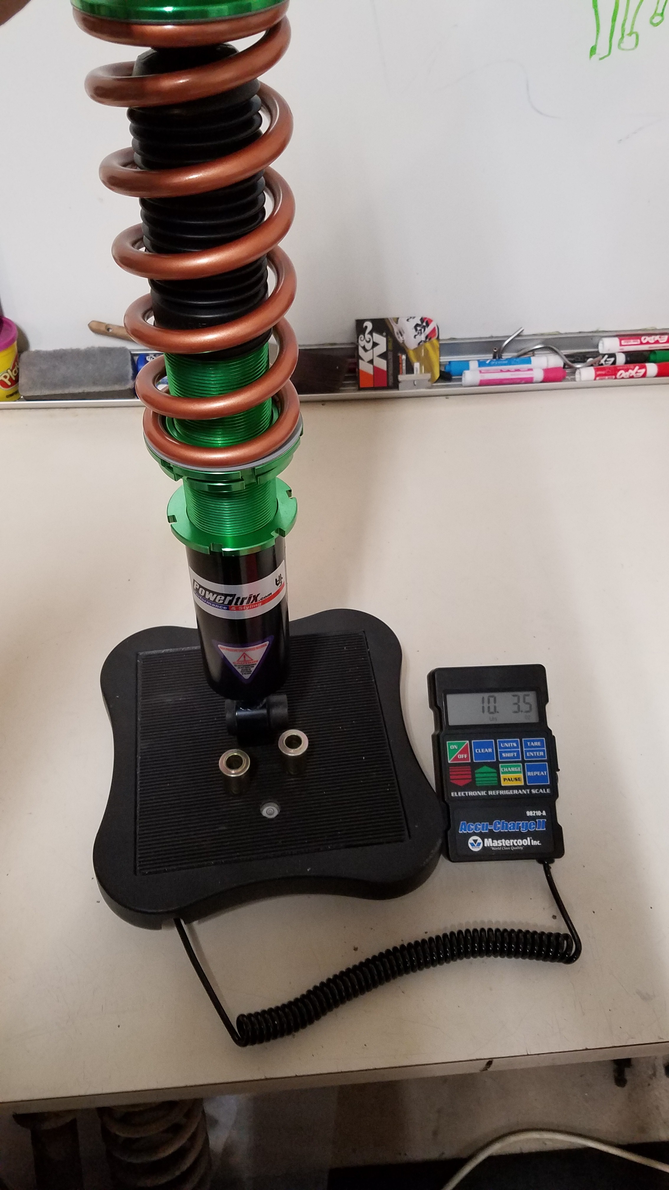
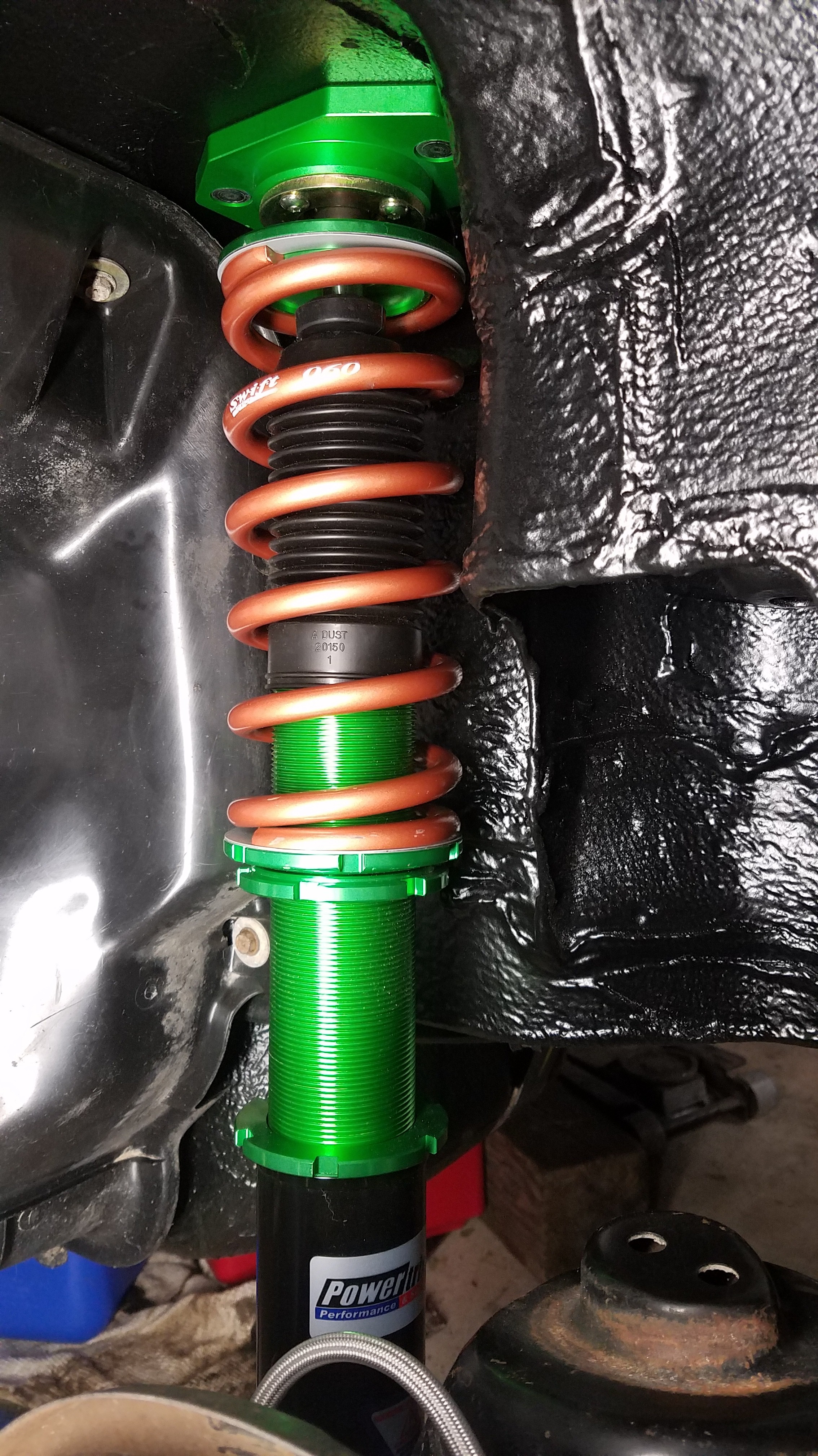
Returning back to suspension upgrades I chose to ditch the traditional strut & shock setup. So I stepped up to fully adjustable coilovers. Unfortunately there is no 100% bolt in solution for the Z31. All units require modification of the front strut tube housings/spindles to accept an weld on coilover adapter. The front struts on the Z31 are actually housings/ tubes that use a shock inserts. The rear coilovers are just a bolt in affair. I initially ordered a set of Stance coilovers. Unfortunately they were on a "2 week" back order. After hearing nothing for an entire month I contacted the company I placed my order with. They assured me they should arrive state side at any moment. Now fast forward to over 3.5 months after my original order placed. They still hadn't received their Stance shipment. Not wanting to wait any longer I cancelled my order & got full refund. Then ordered a set of Powertrix Road & Track Ultralights w/Swift spring upgrade. I received my order within 6 days. That's even with my local Fedex hub requiring me to pick up my package from a authorized drop point. Funny thing was my nearest drop point was a Walgreens. This added another entire day to the shipping time. Not bad considering these were built to order. The ultralights are 3lbs lighter per coil than their traditional Road & Track version. There's a over a 9lb savings over each OEM front strut assembly. Sprung weight is roughly 3-4 times its un-sprung weight. So these savings "should" make a significant difference. The chassis was made more stable with the addition of a Cusco strut tower bar. My engine bay quickly became too "busy" due to the green coilover top hats & blue strut tower bar mounts. So you guessed it.... I powder coated these too.
-
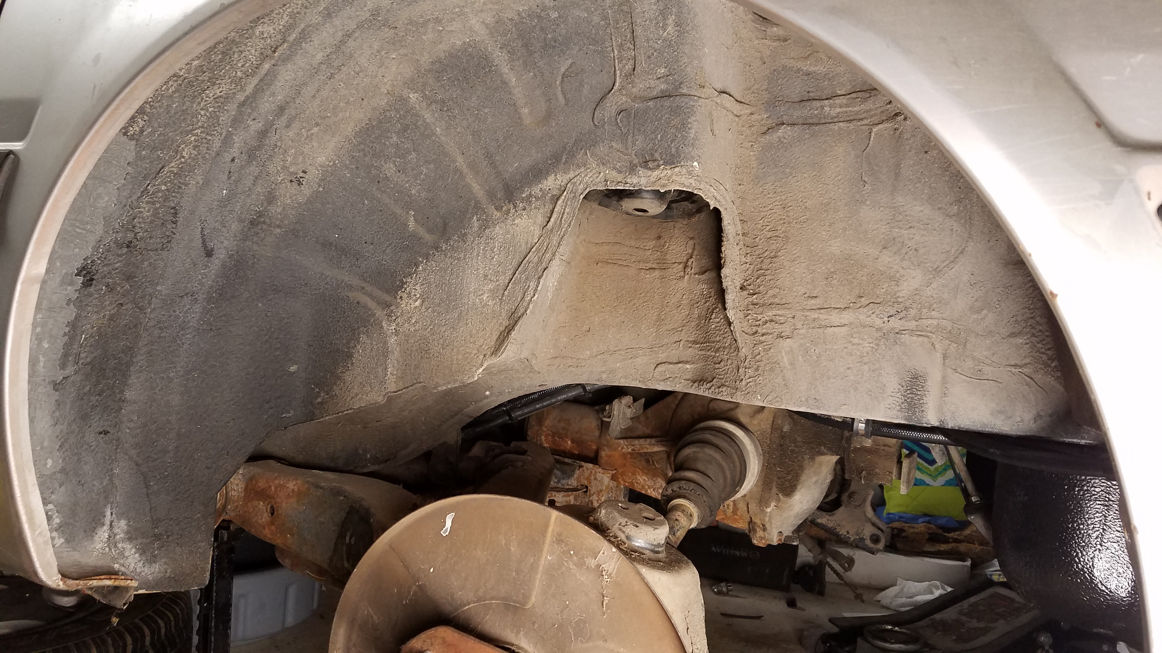
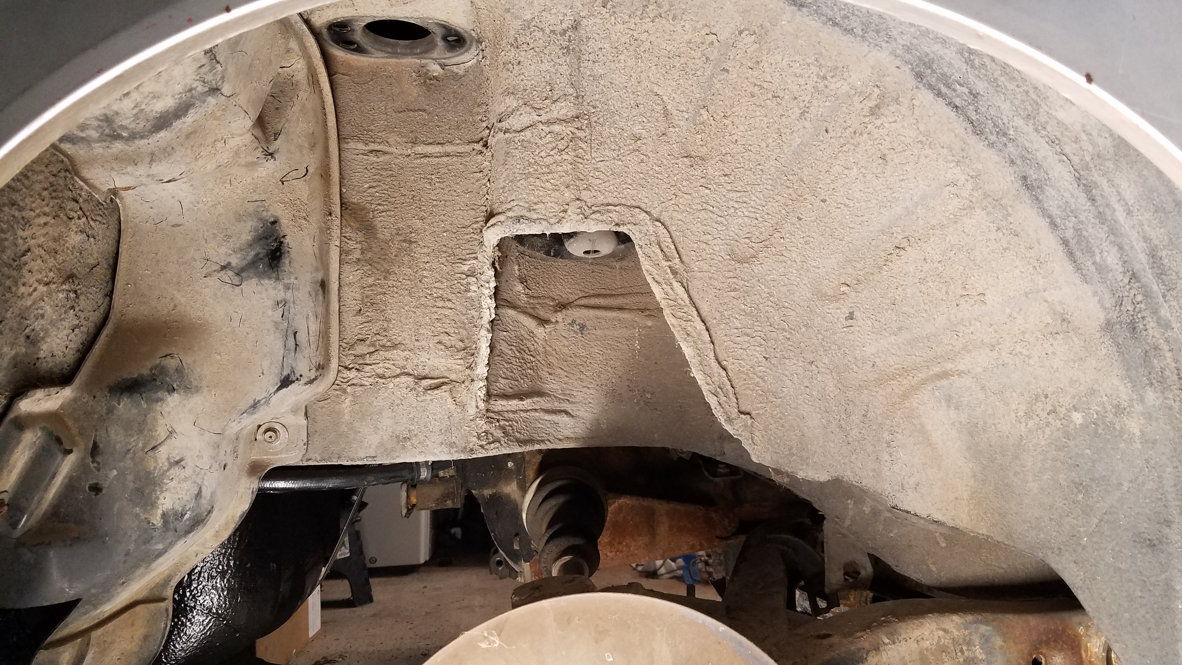
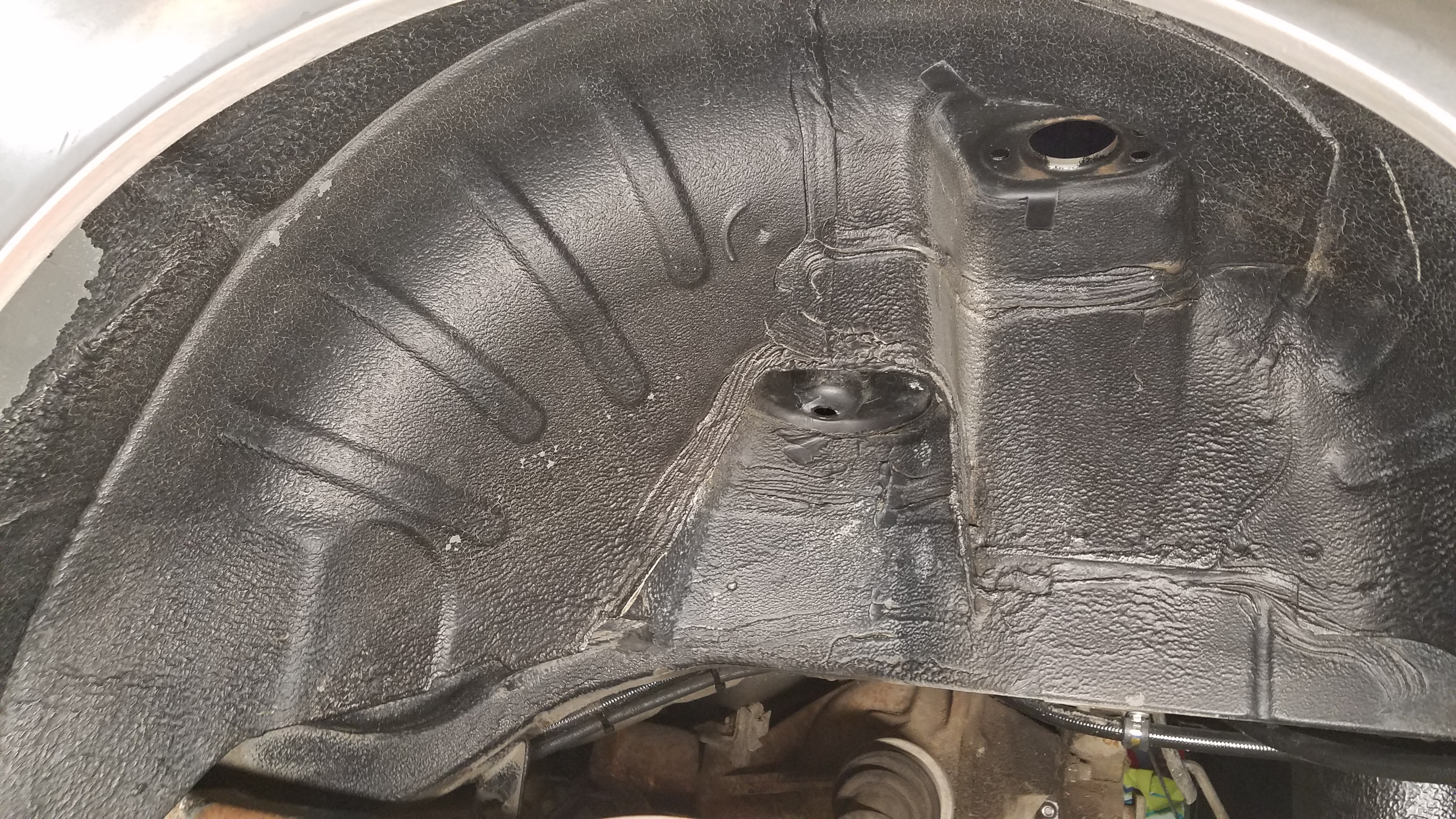
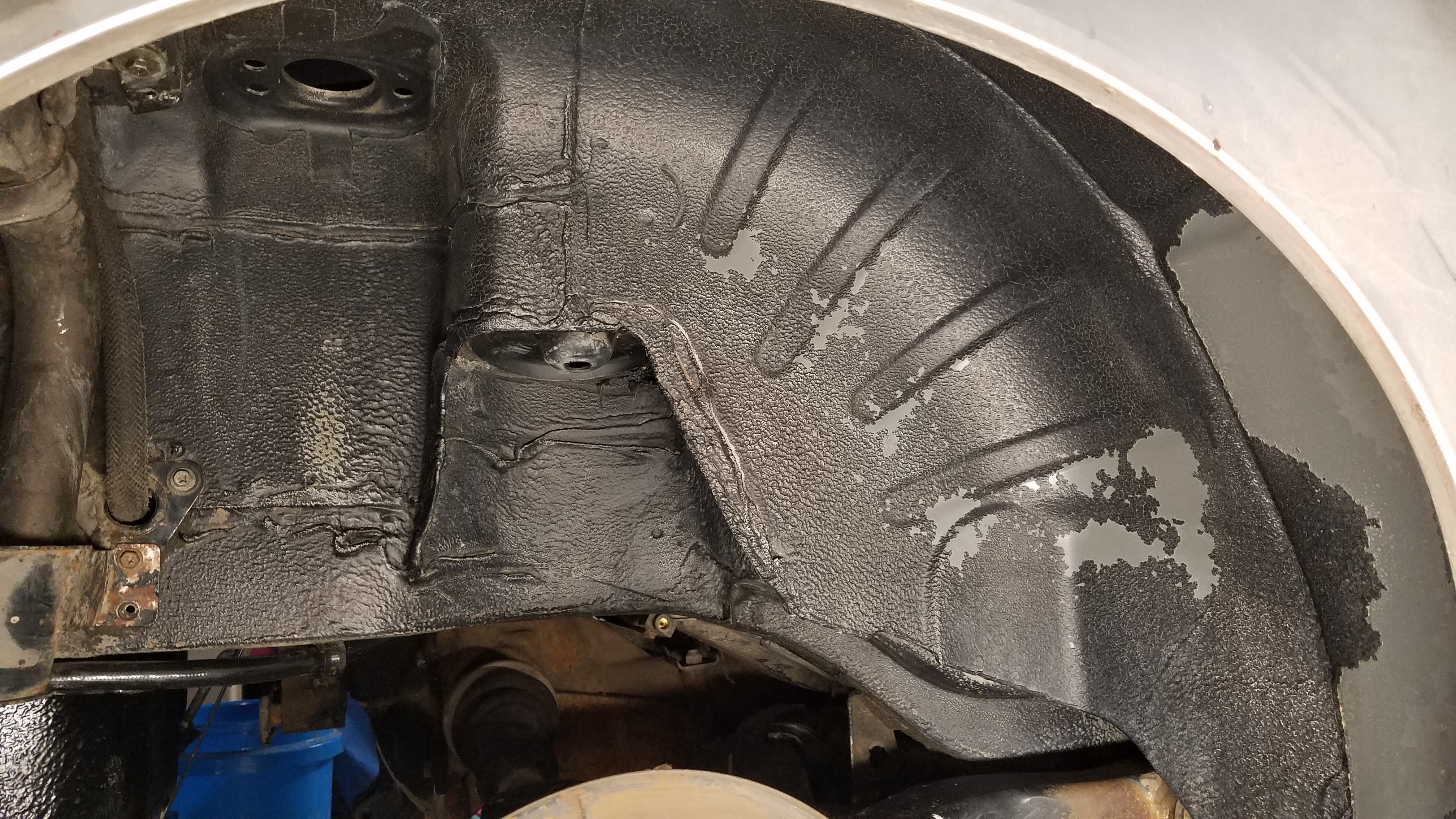
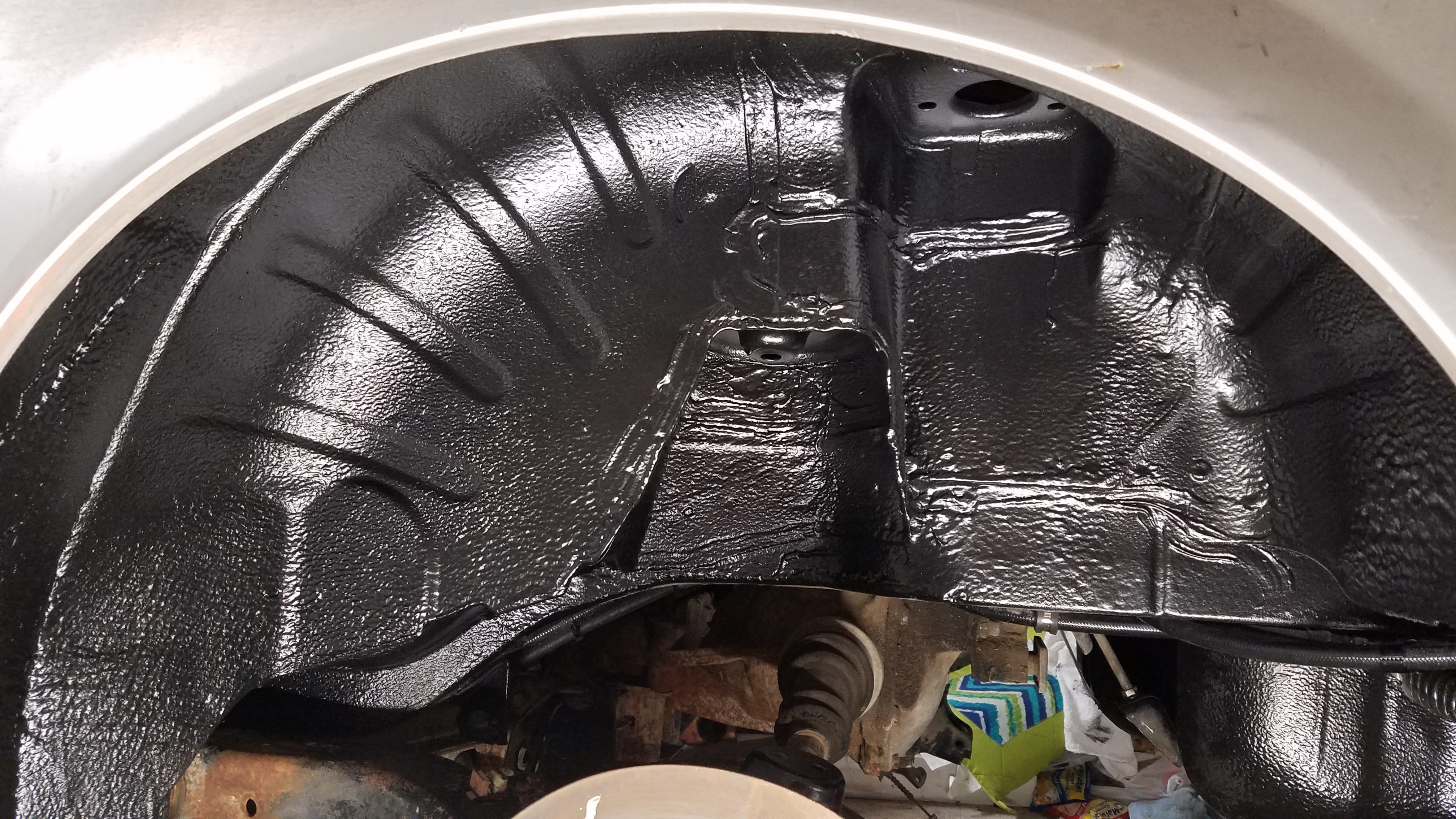
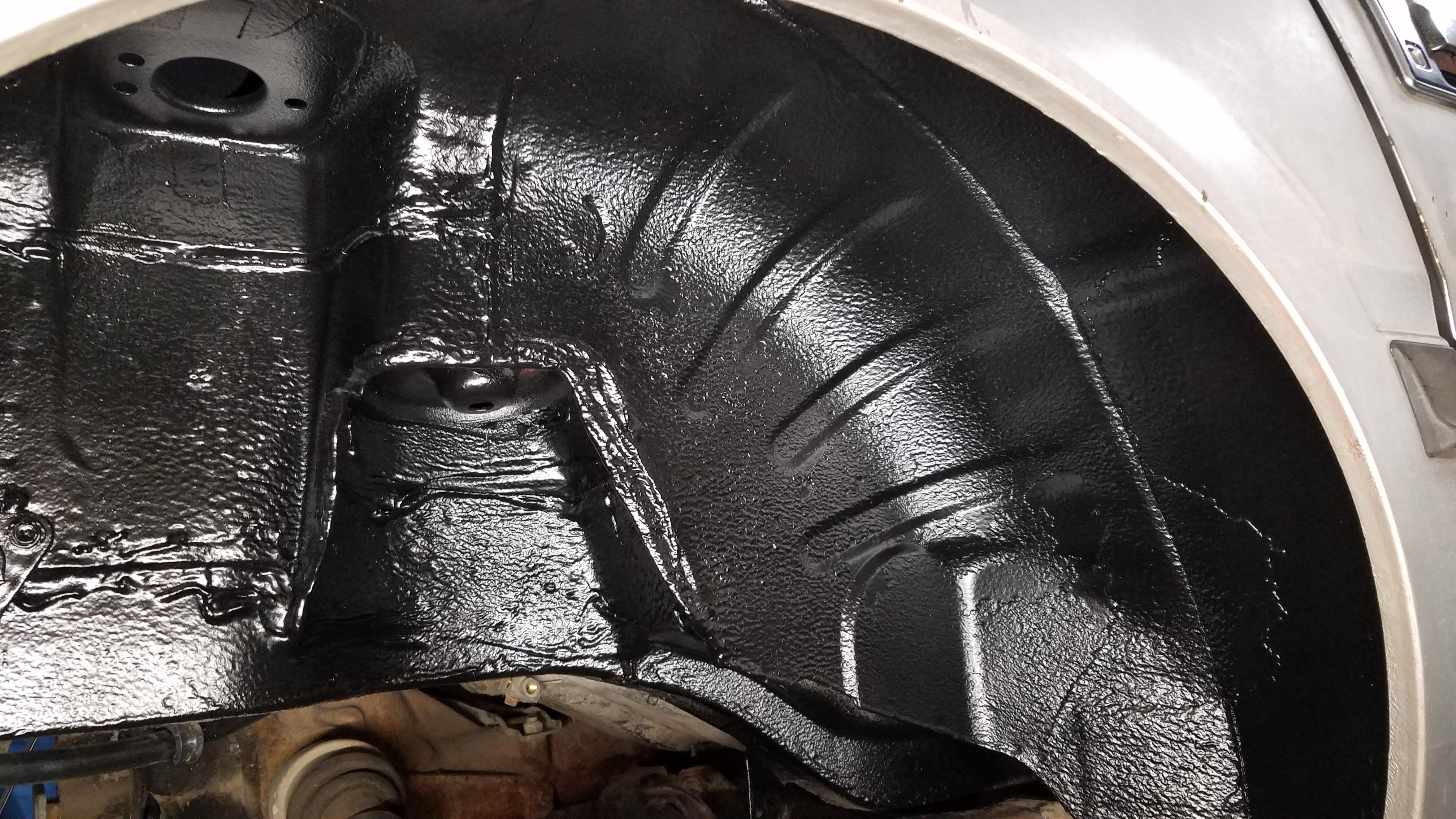
Moving on I removed the rear springs & shocks. So I could properly clean/prep the rear wheel wells before applying a fresh rubberized undercoat.
-
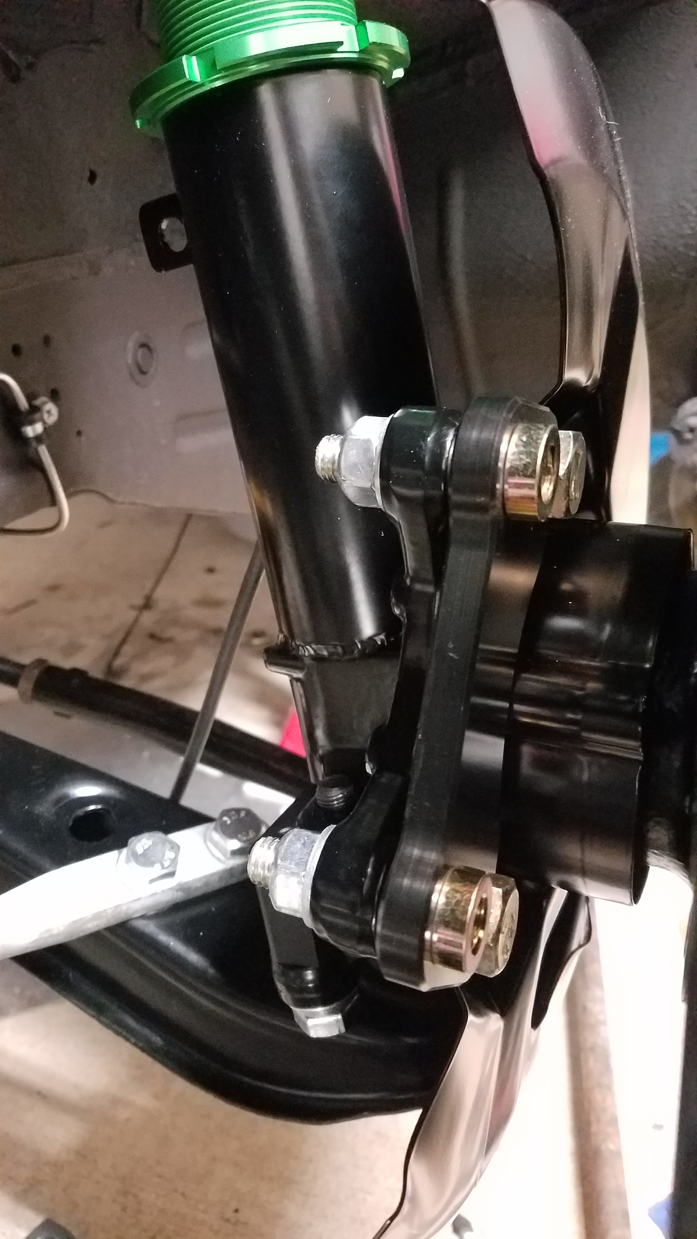
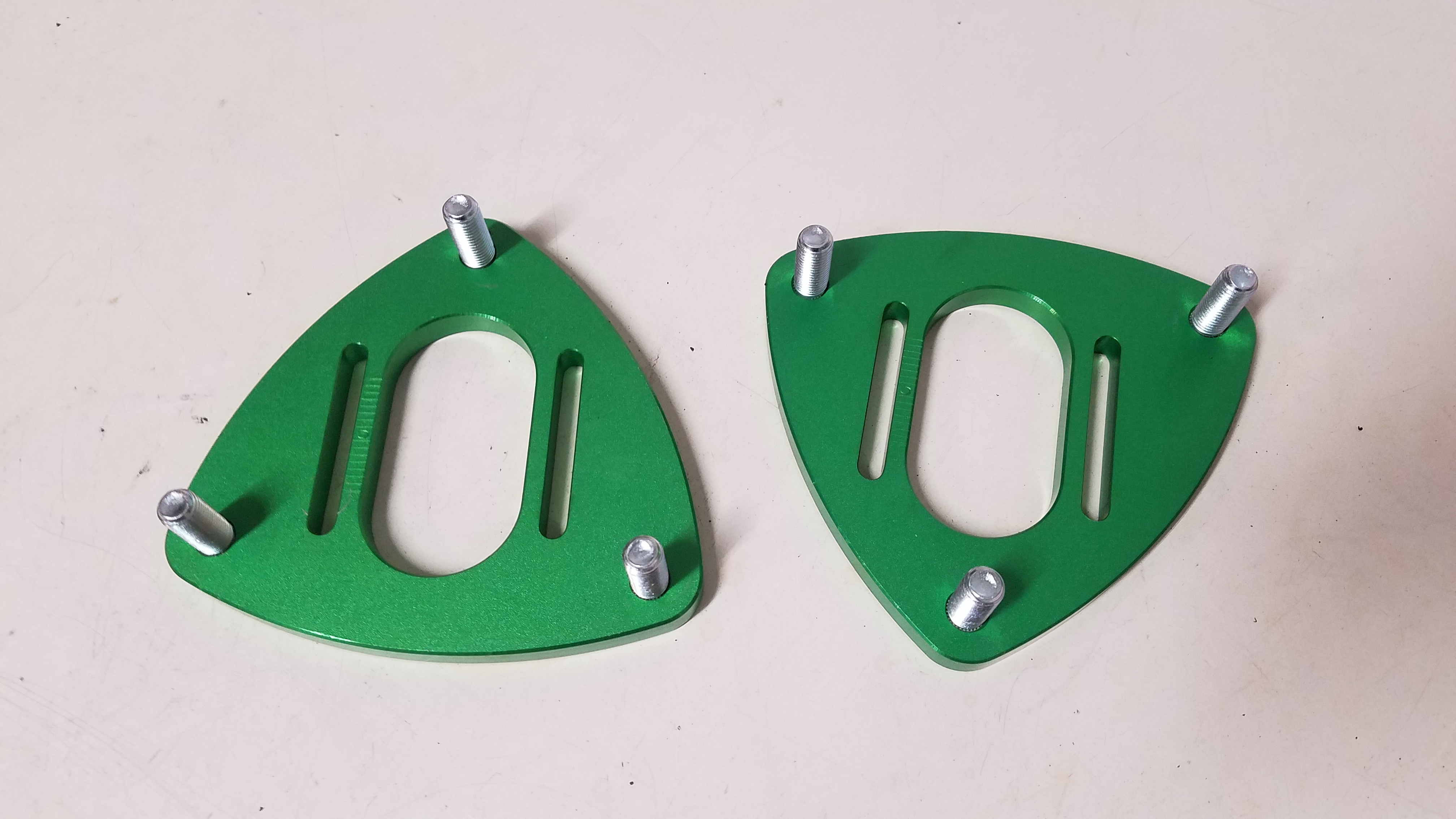
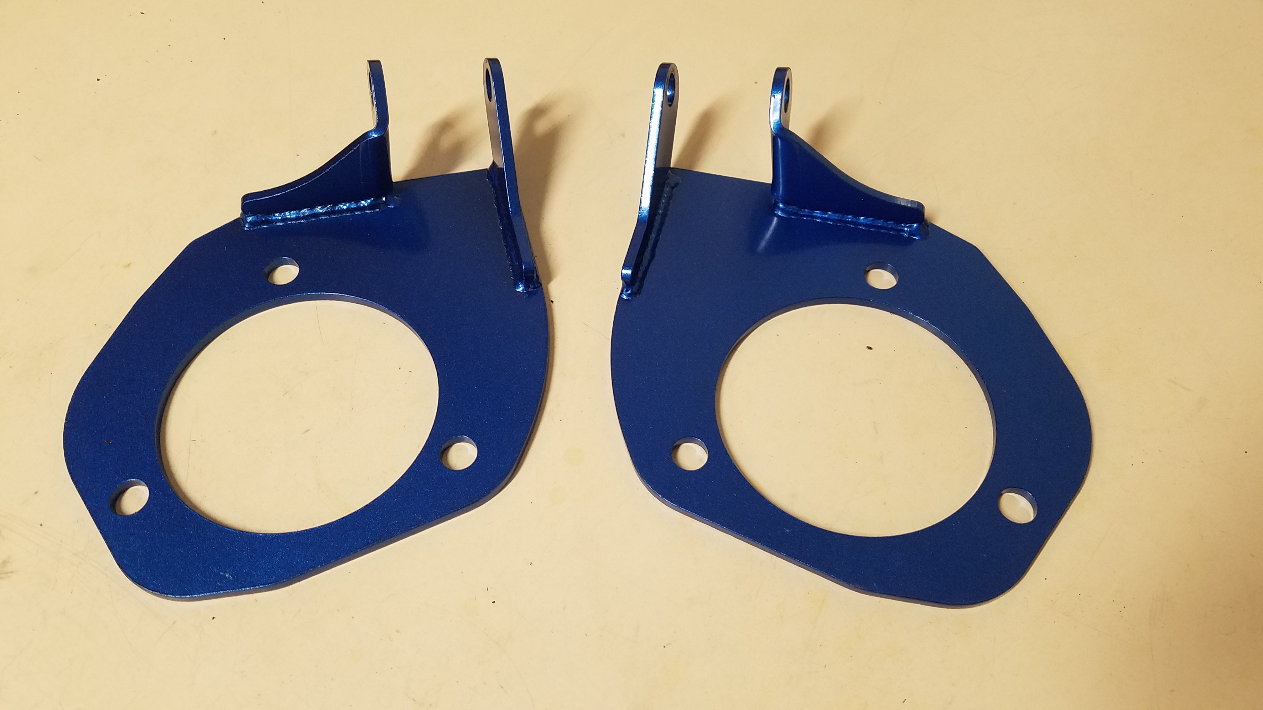
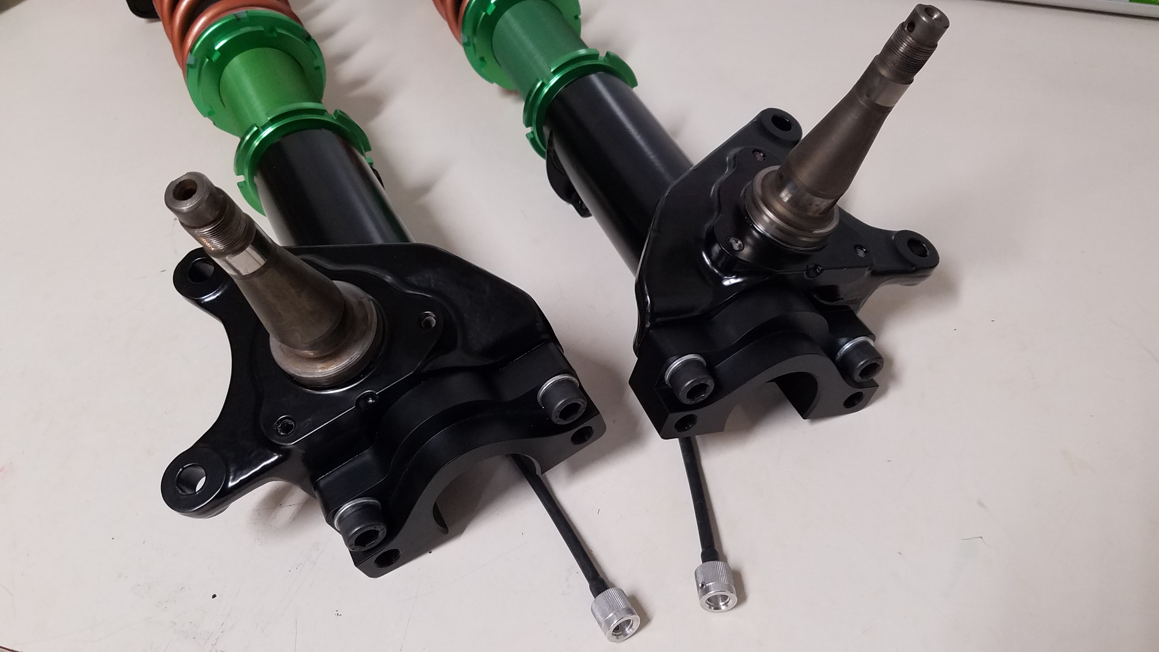
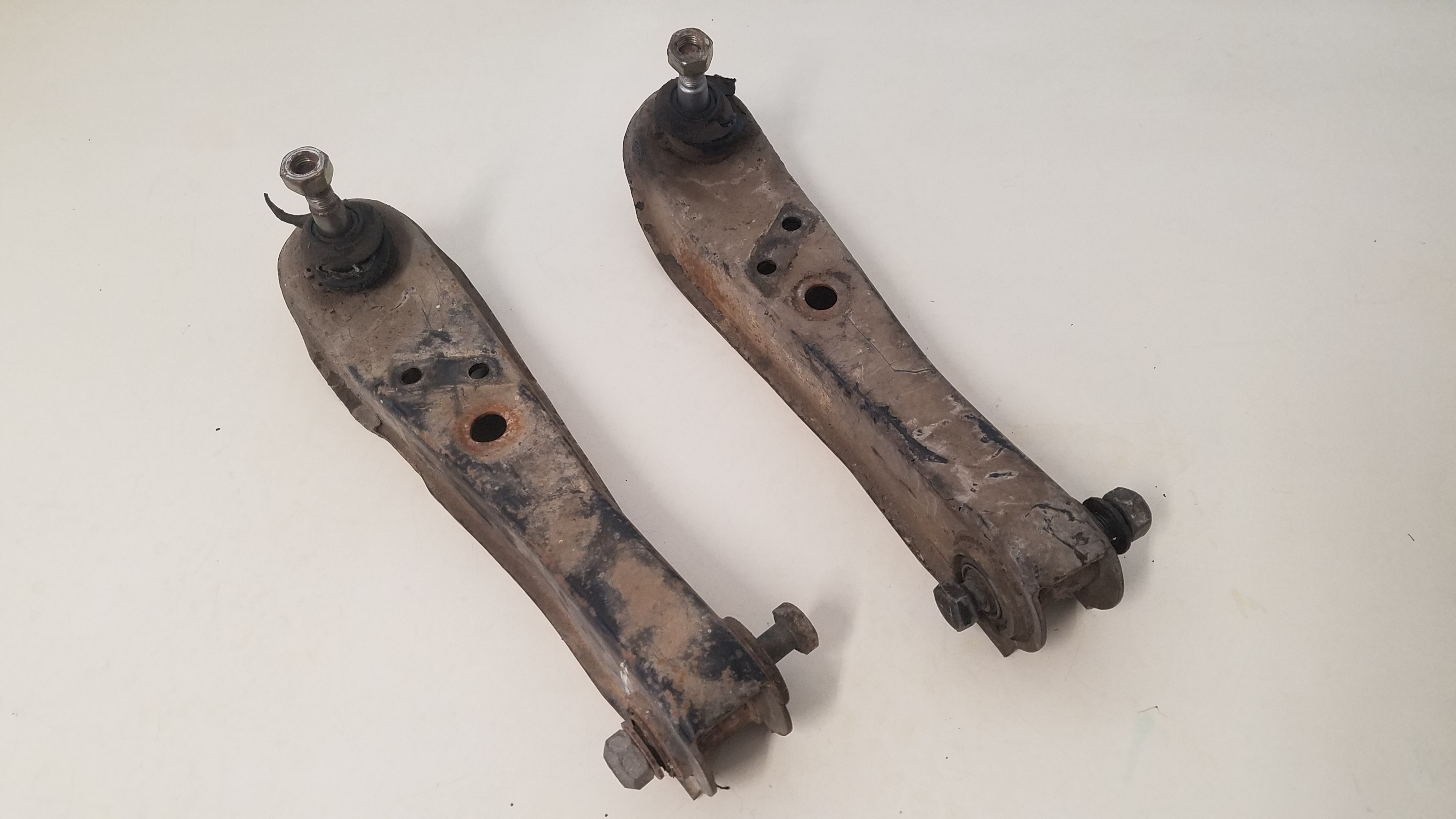
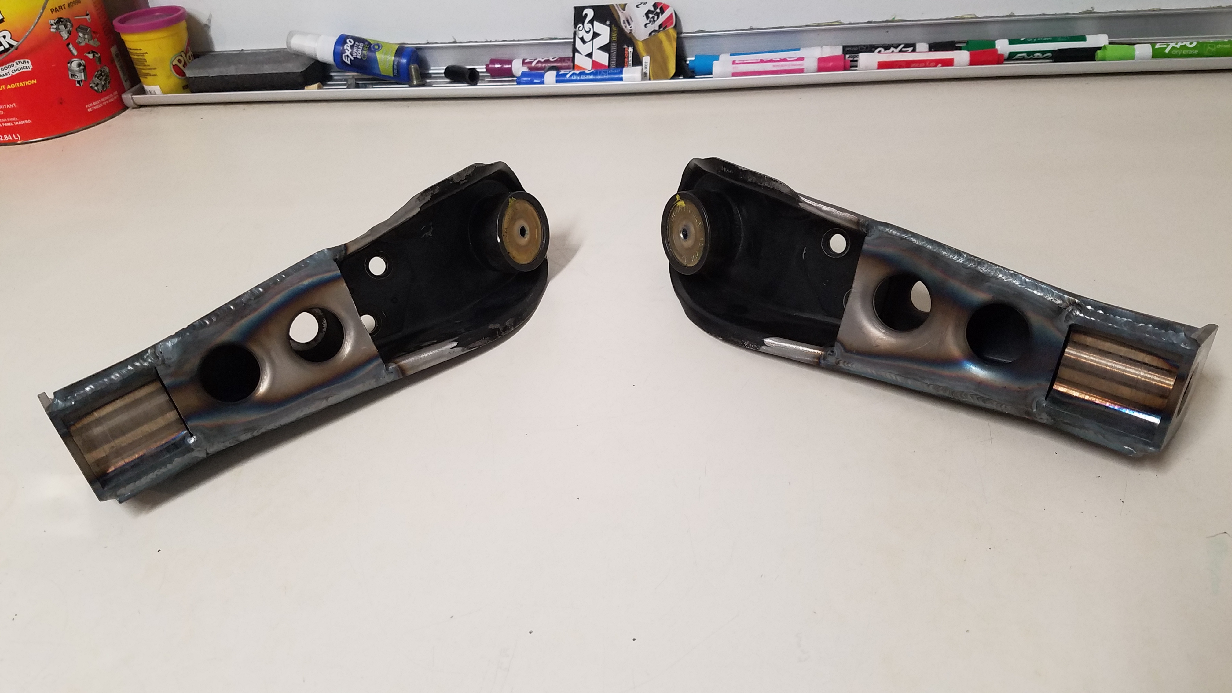
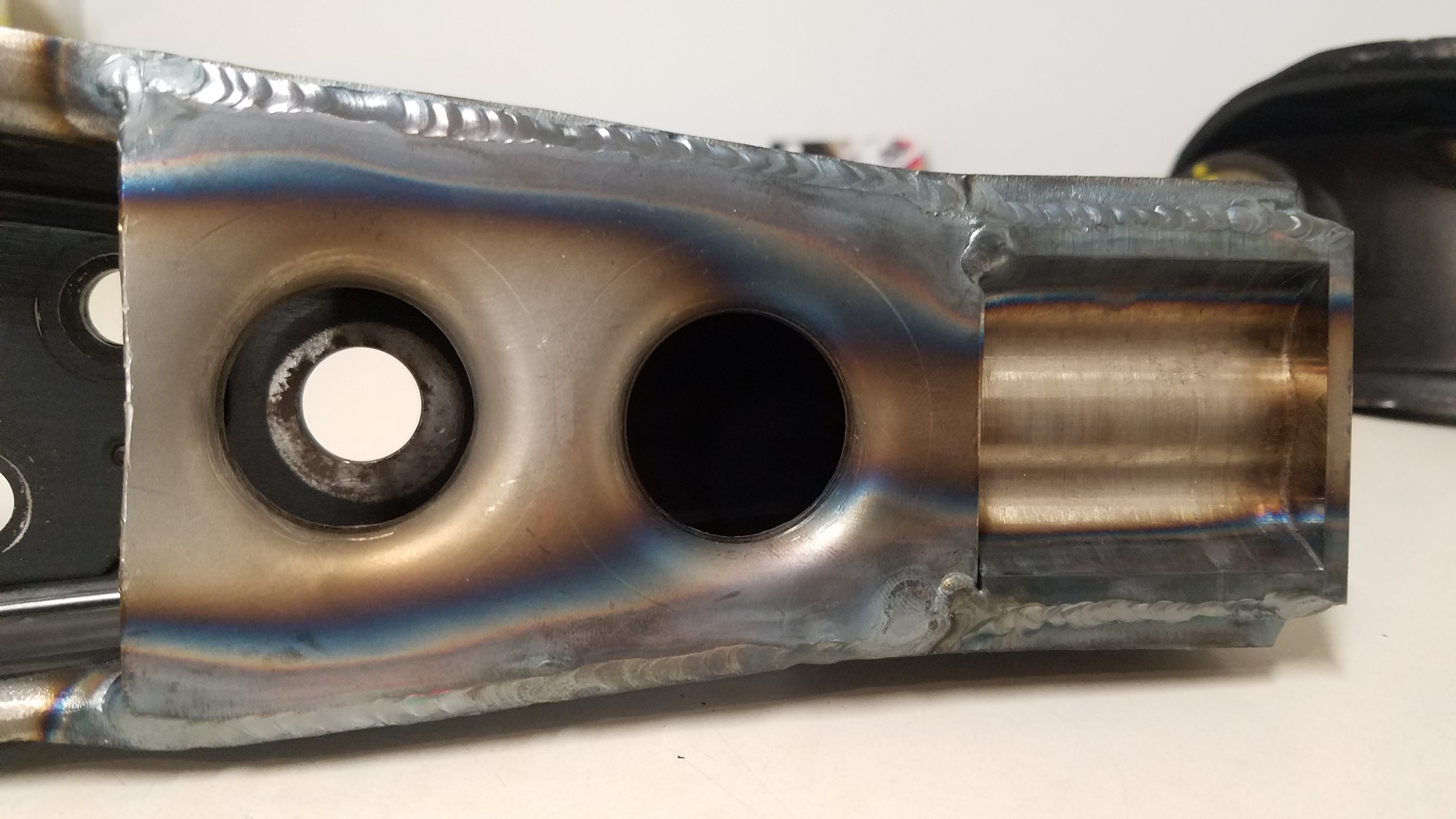
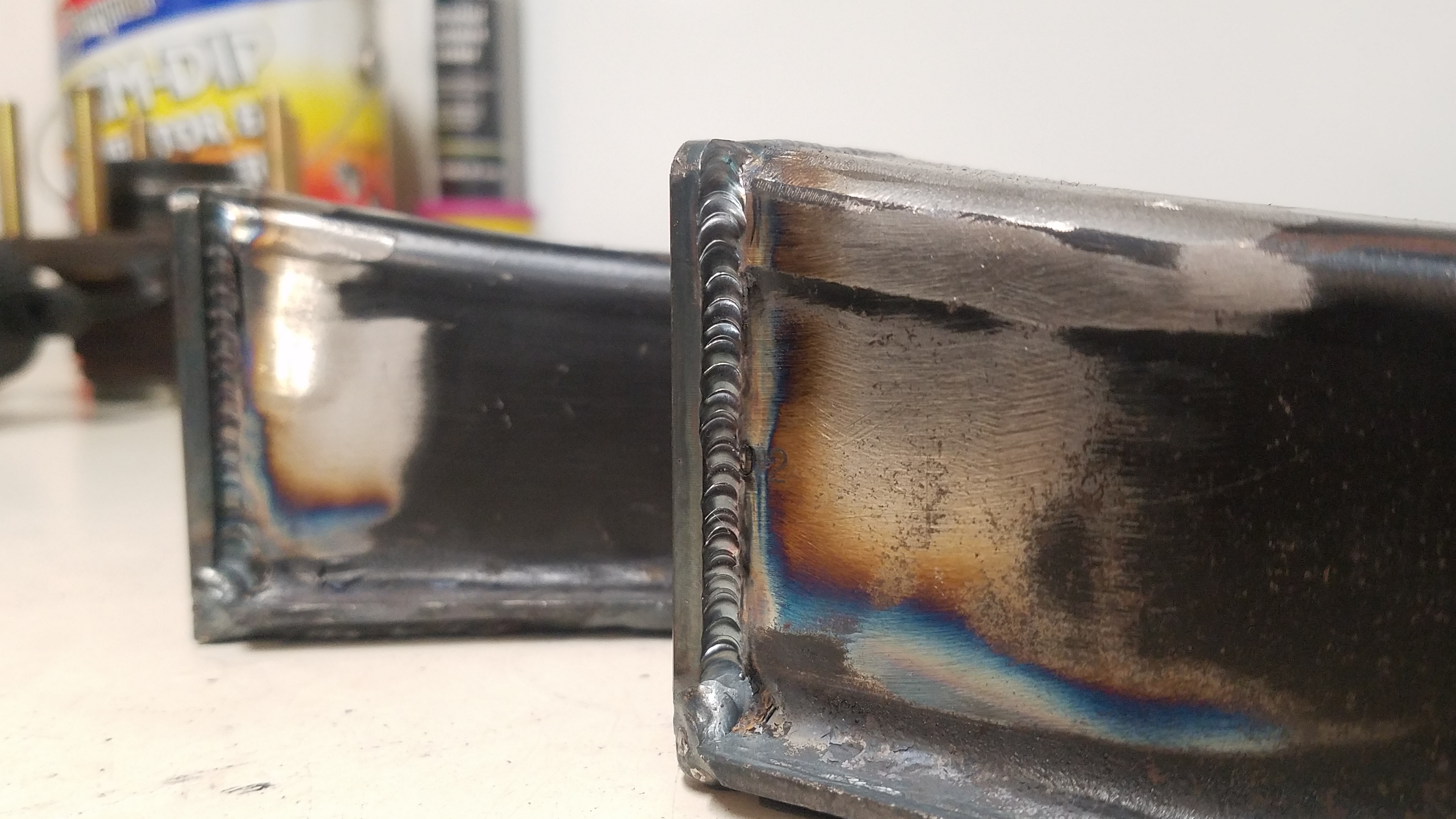
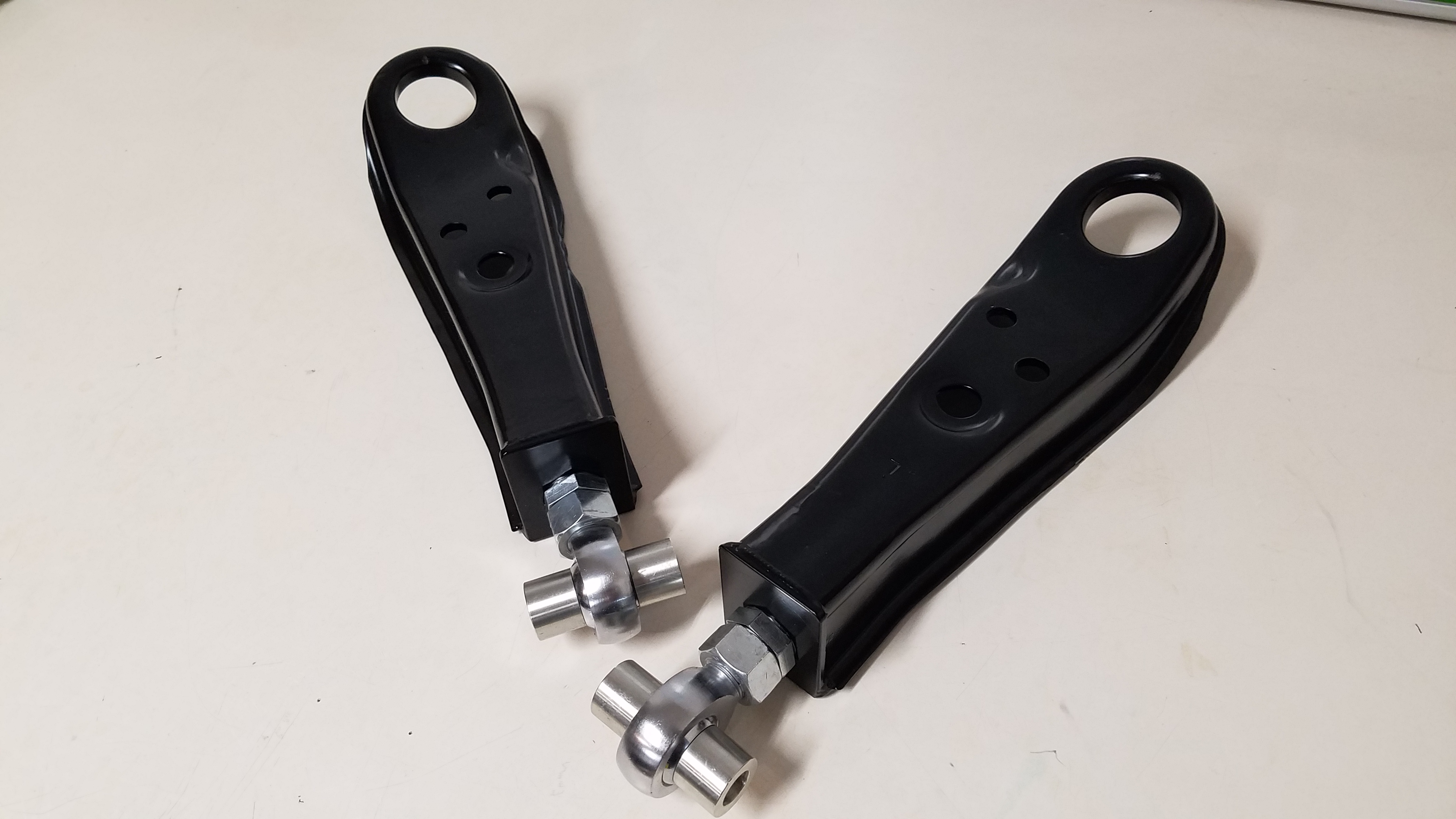
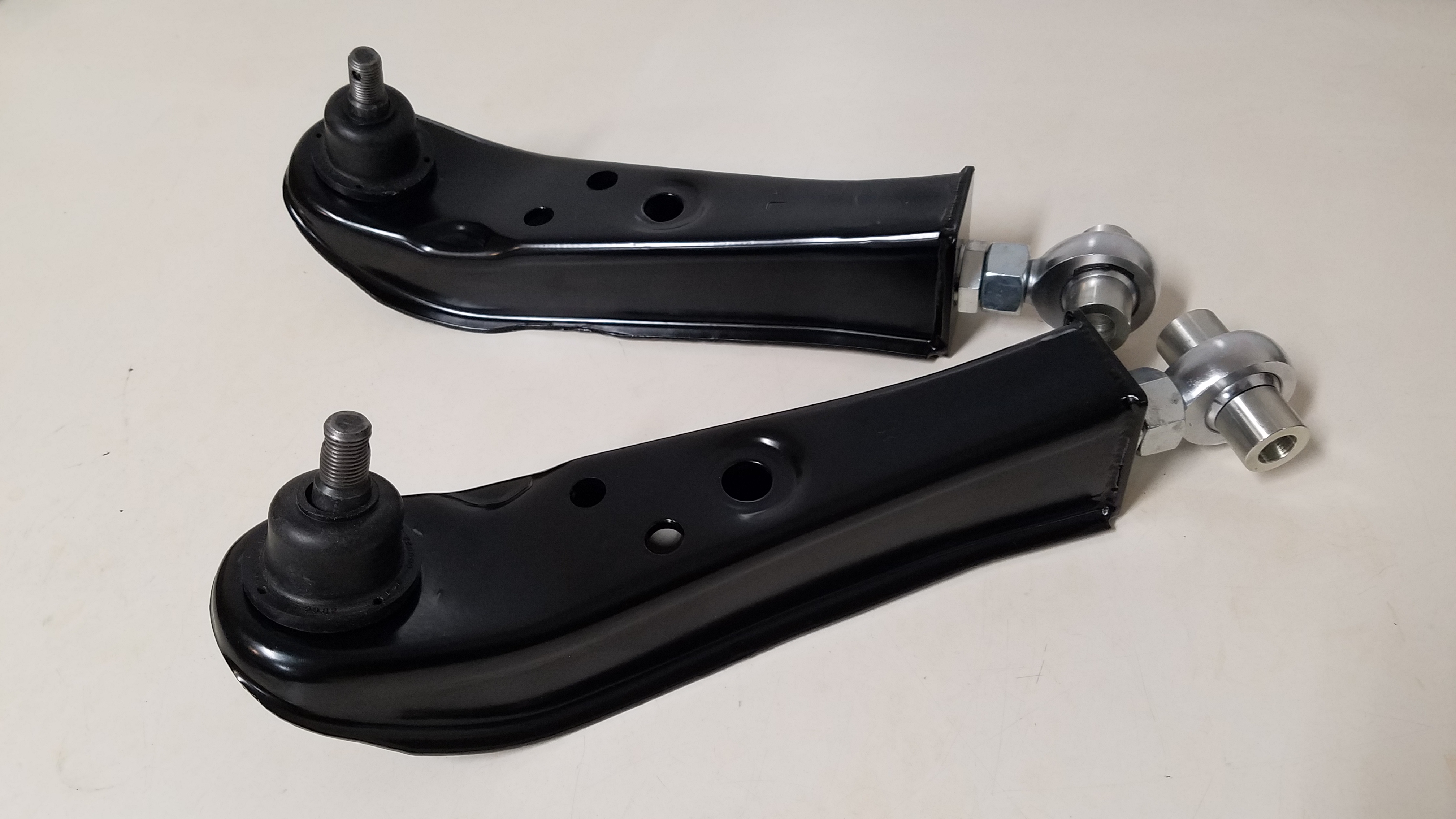
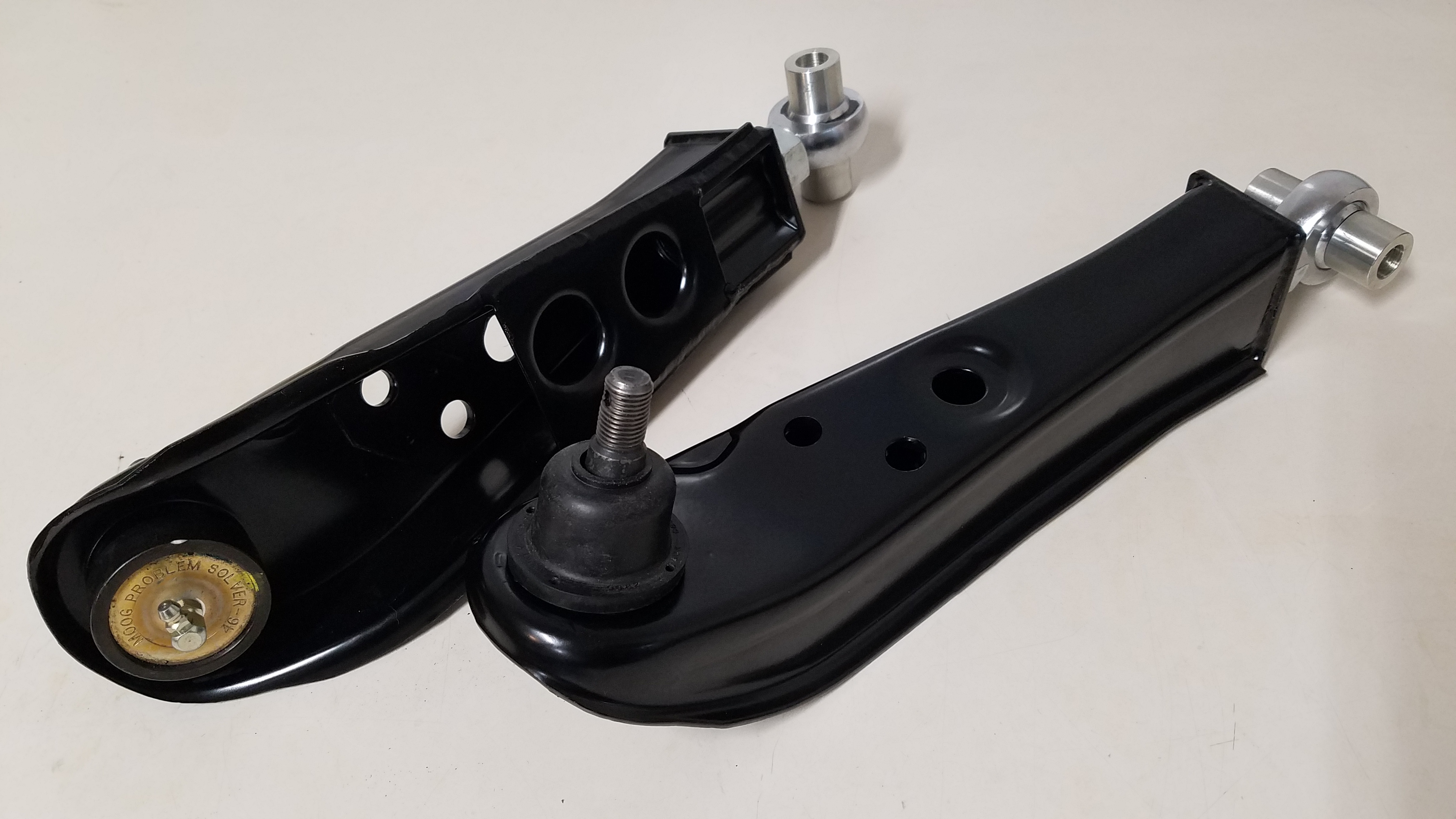
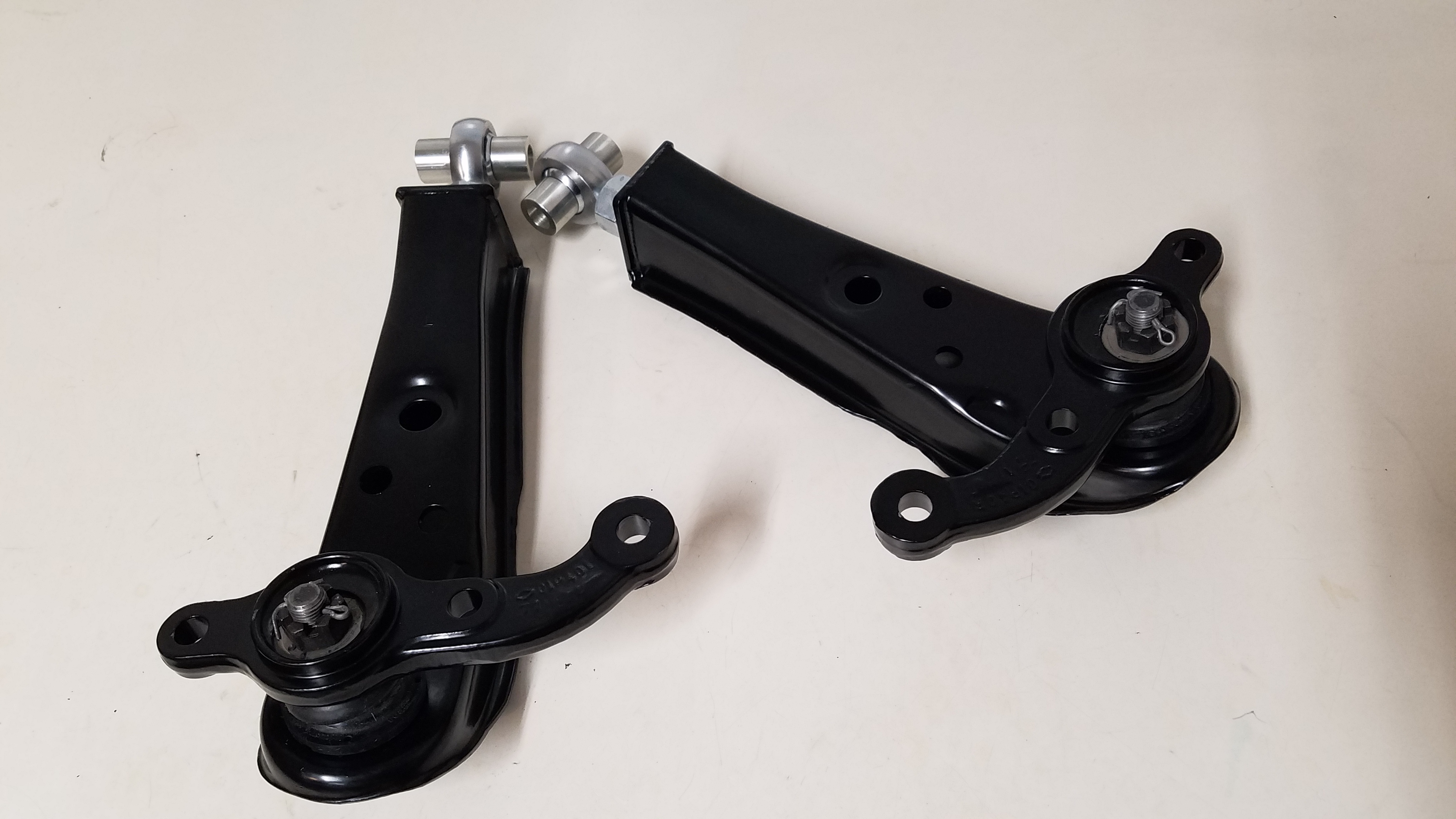
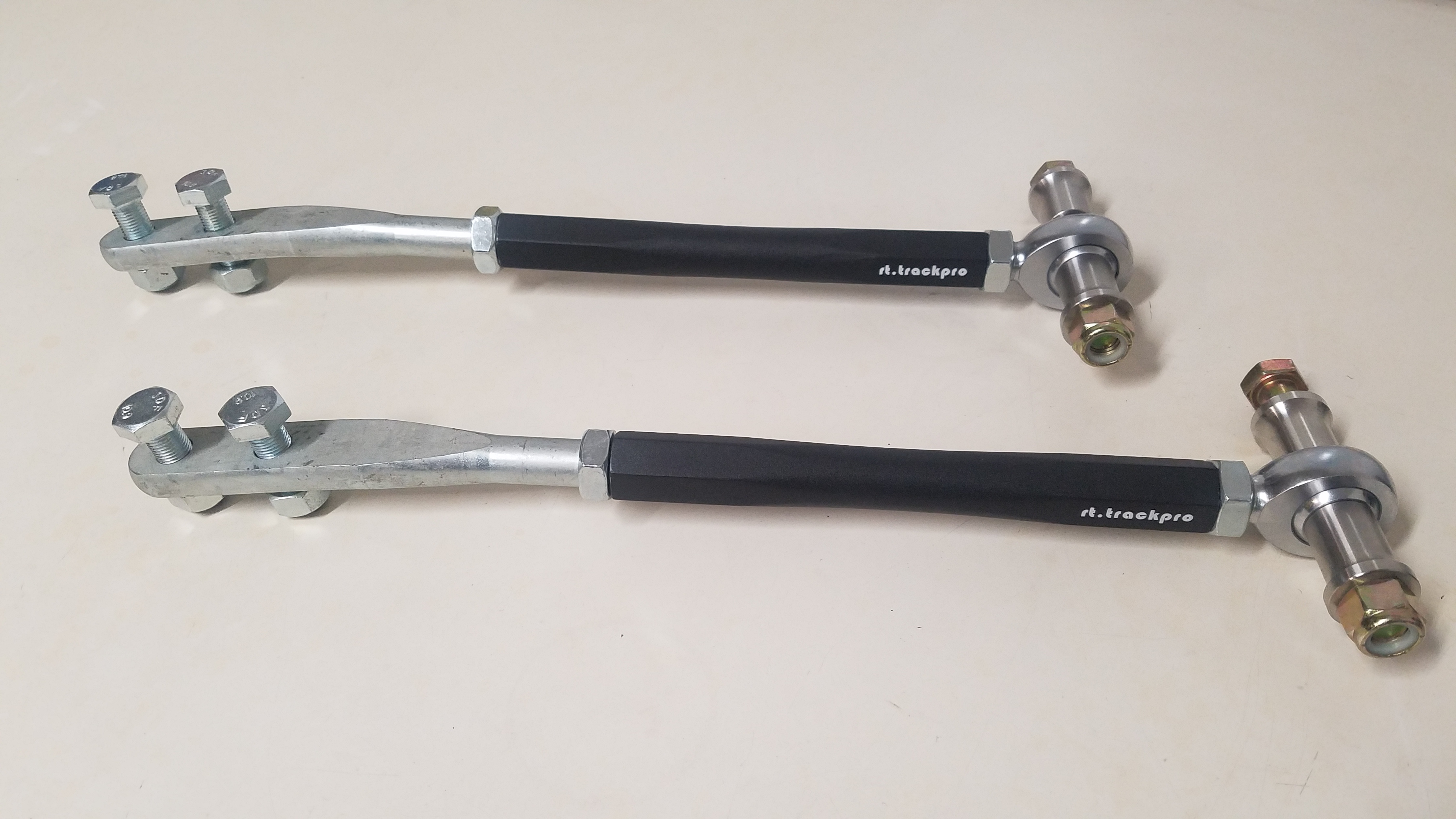
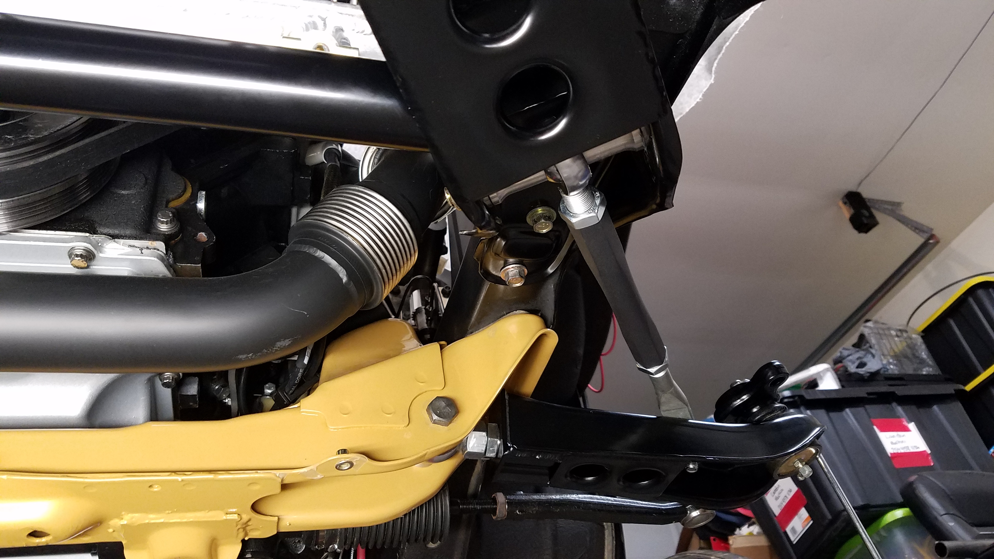
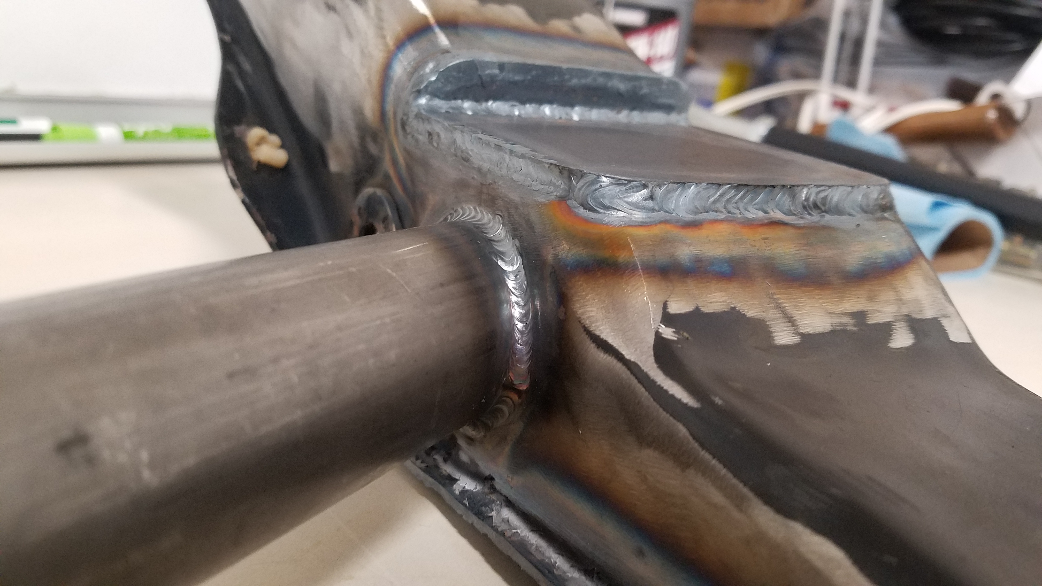
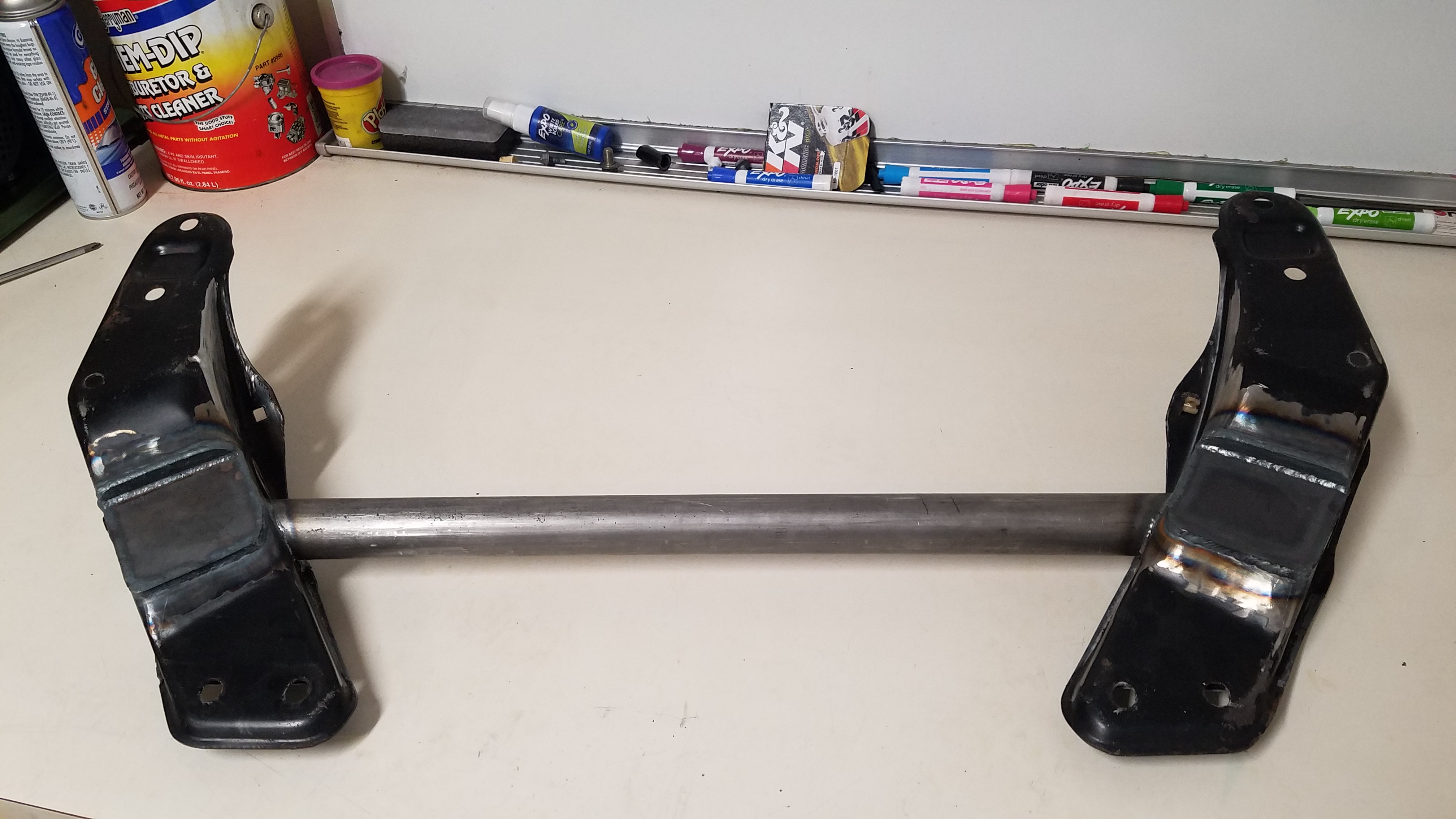
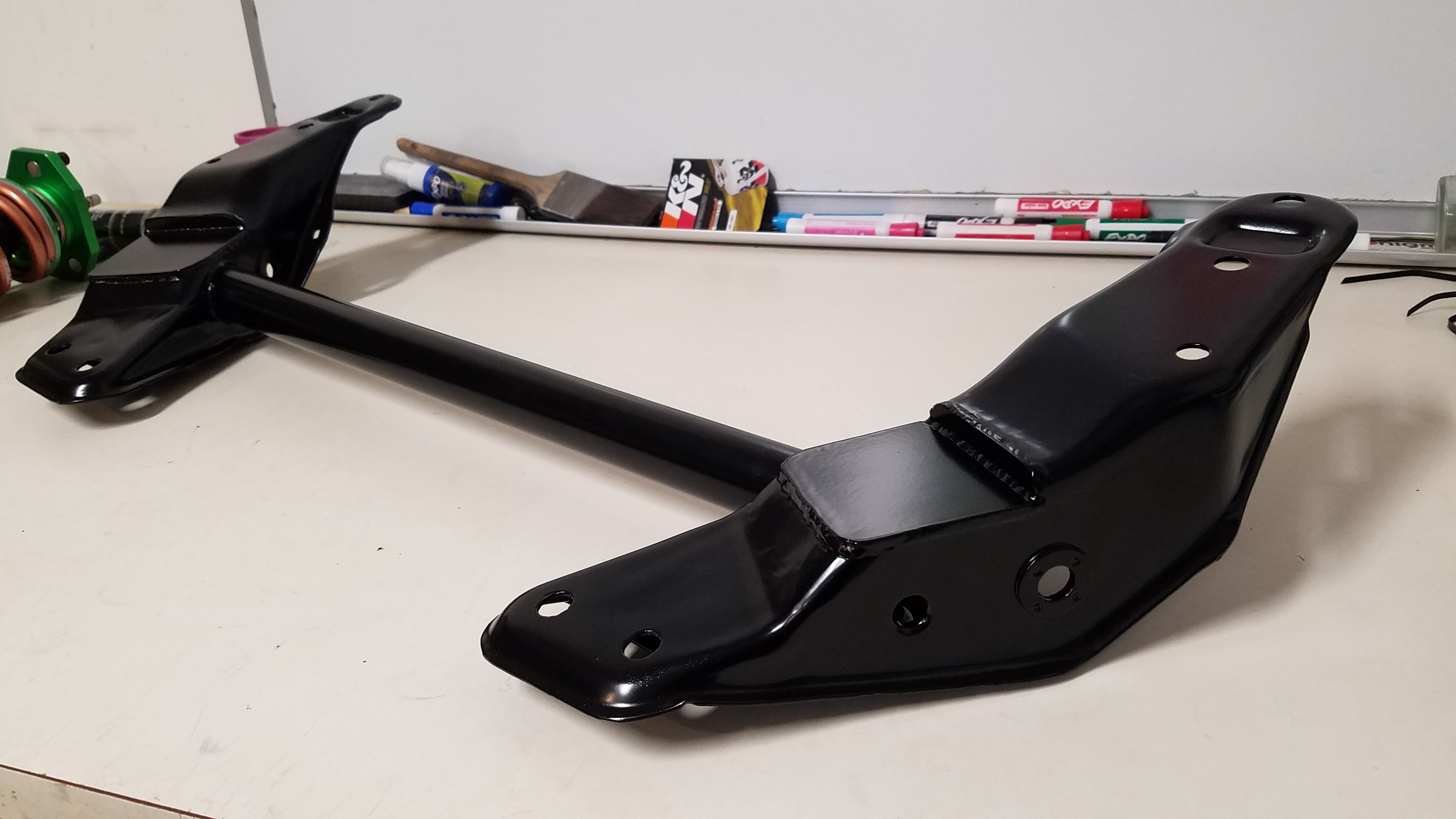
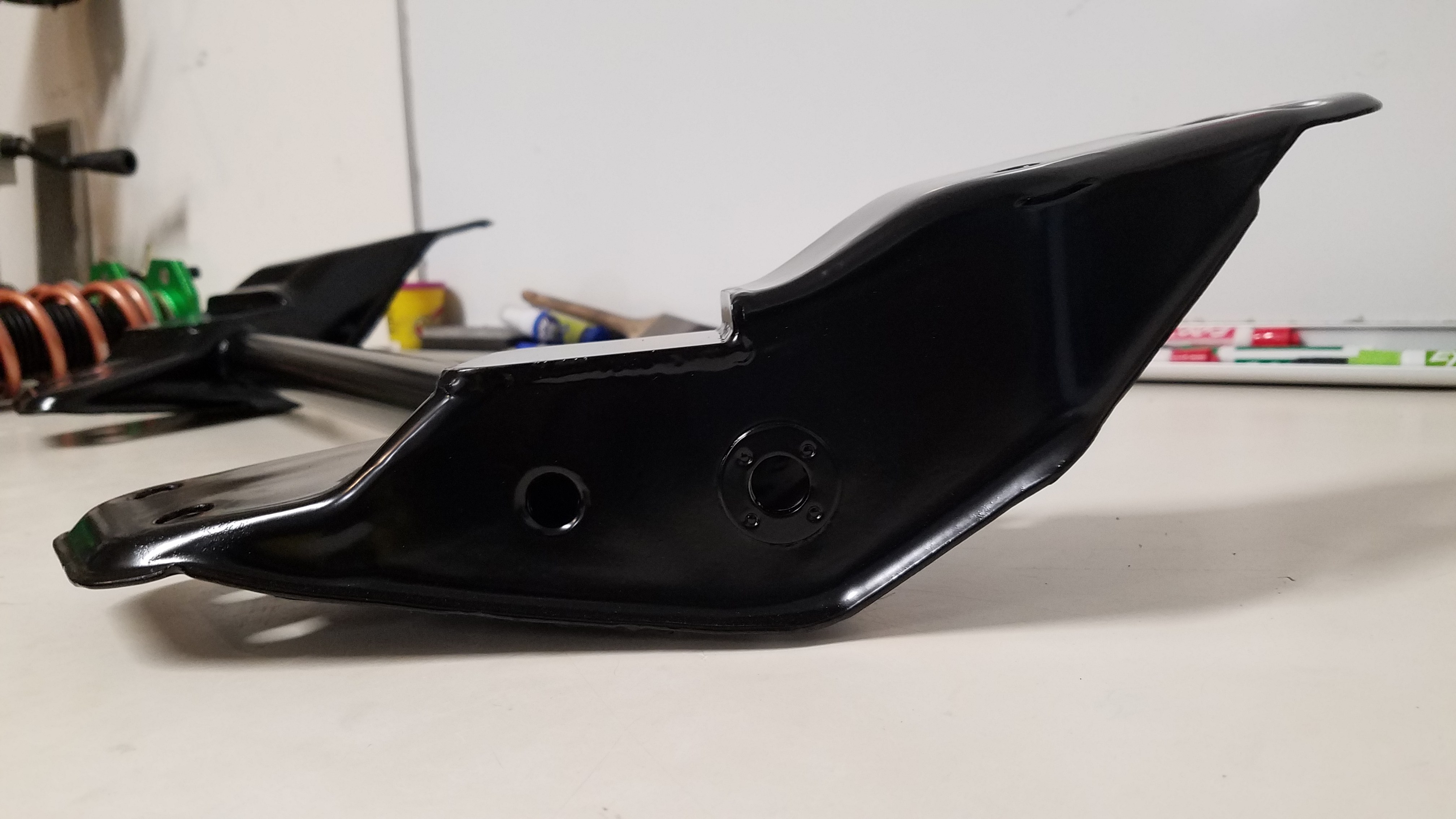
I modified my control arms utilizing Rt.Trackpro's Adjustable Control-arm kit. This kit allows you to add adjustability to the factory control arms. The section with factory control bushing is removed. Then replaced by The threaded insert & QA1 heim joint. The control arms were also boxed in with dimpled gussets & powder coated. Replacement Moog ball joints were installed followed by freshly powder coated OEM steering knuckles. Rt.Trackpro's Adjustable Tension-rods were also added to the mix. These units completely replace the factory tension rods all together. These also have QA1 Heim joints instead of a factory style bushings.
-
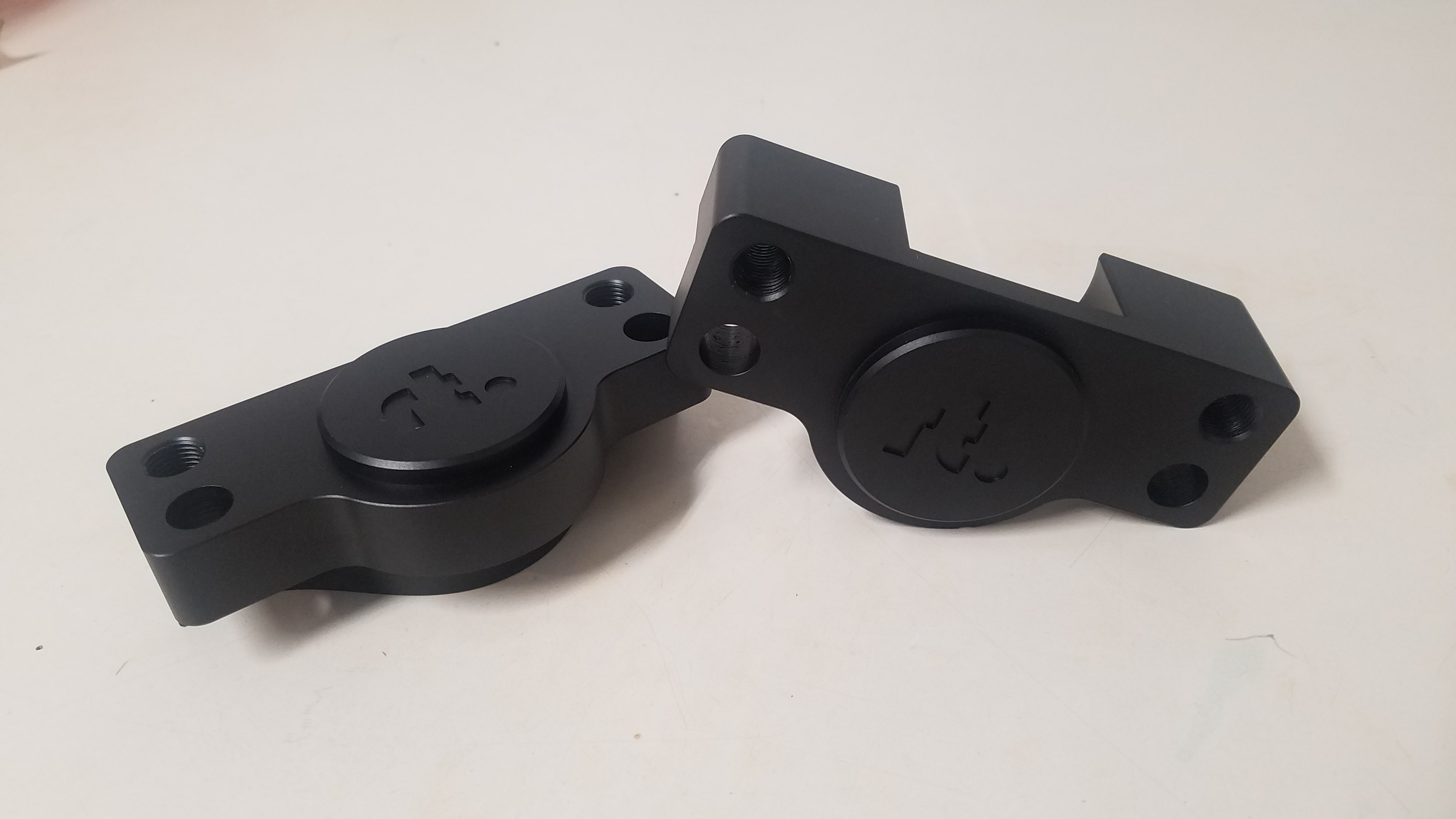
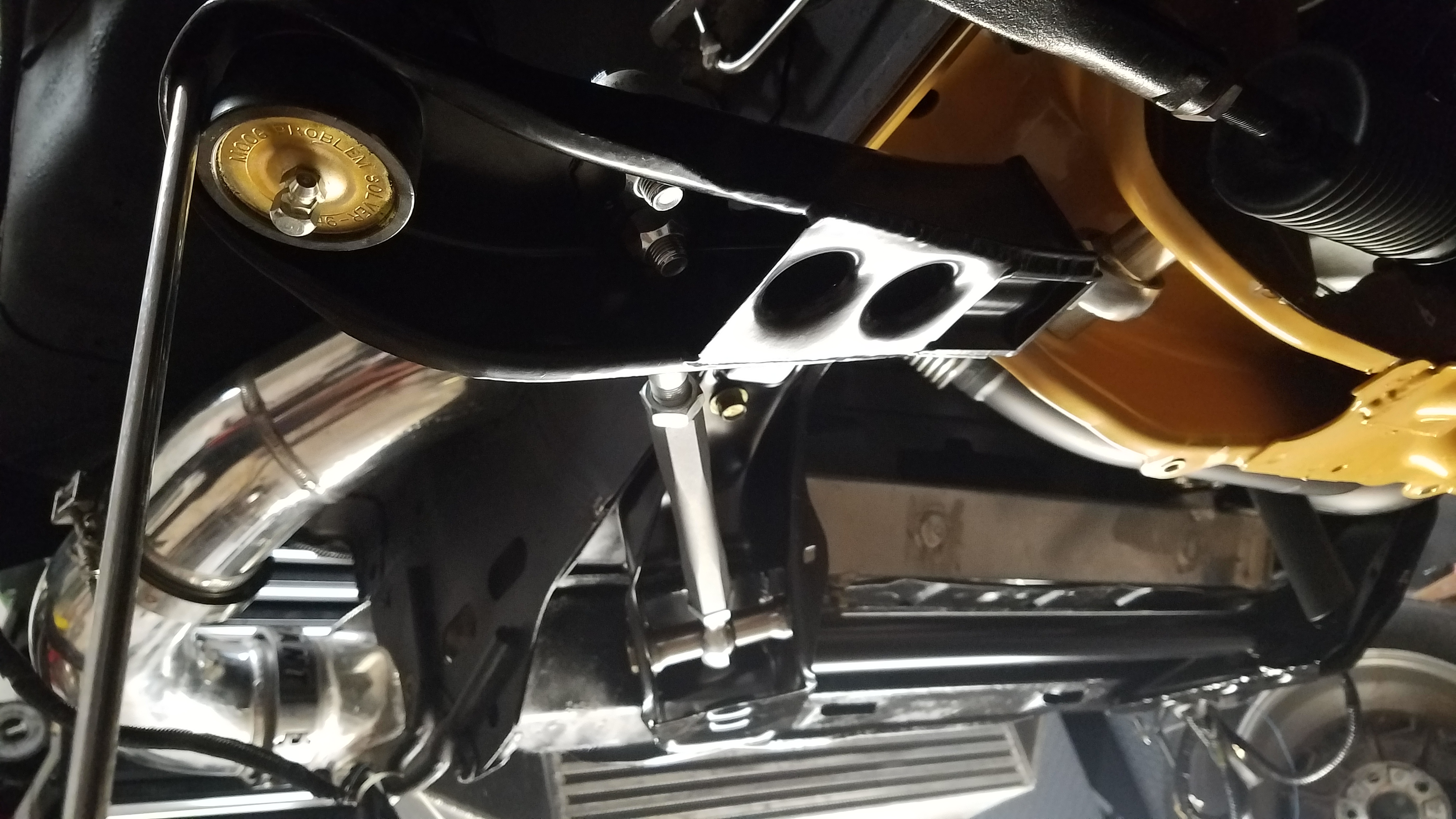
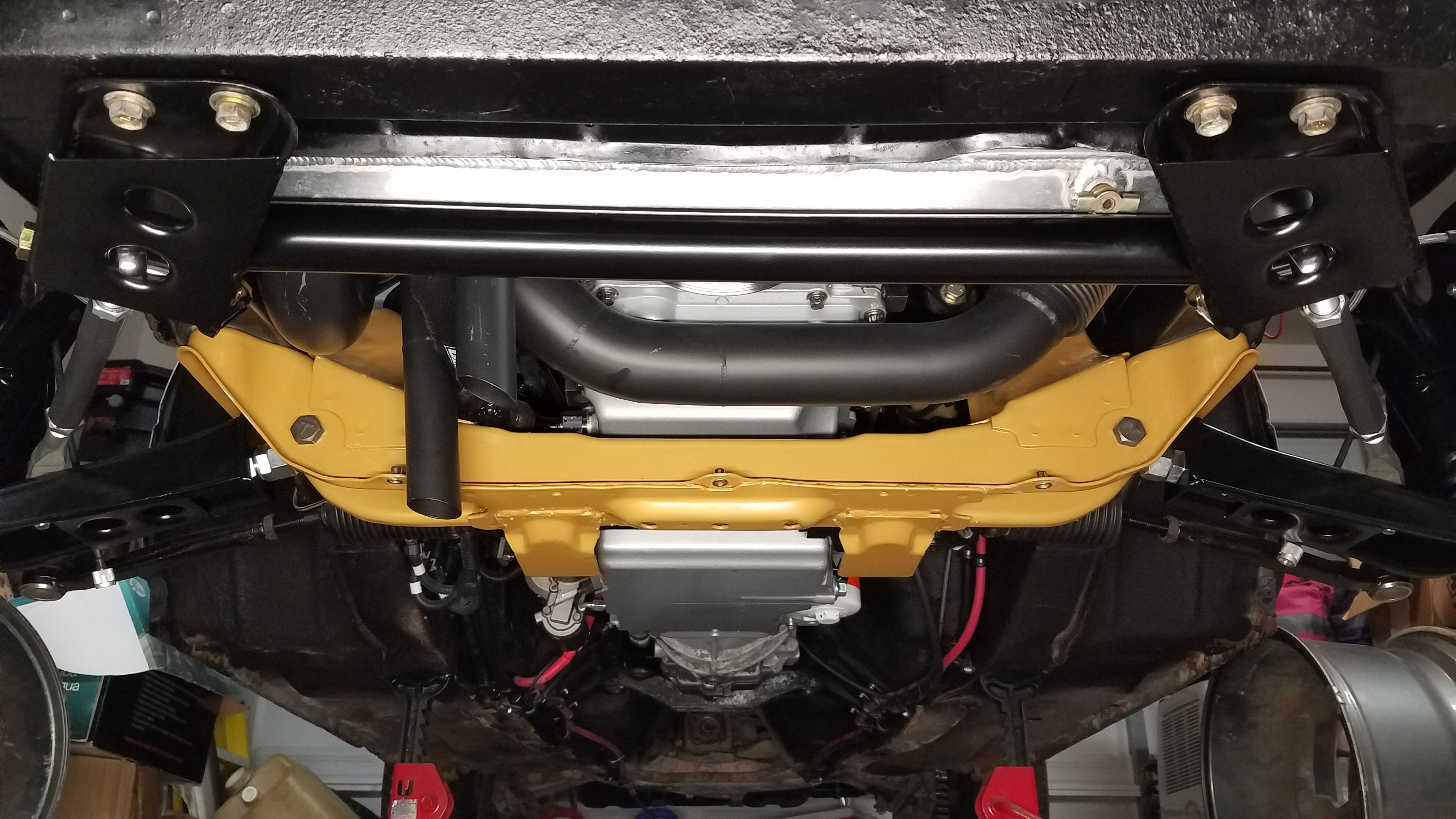
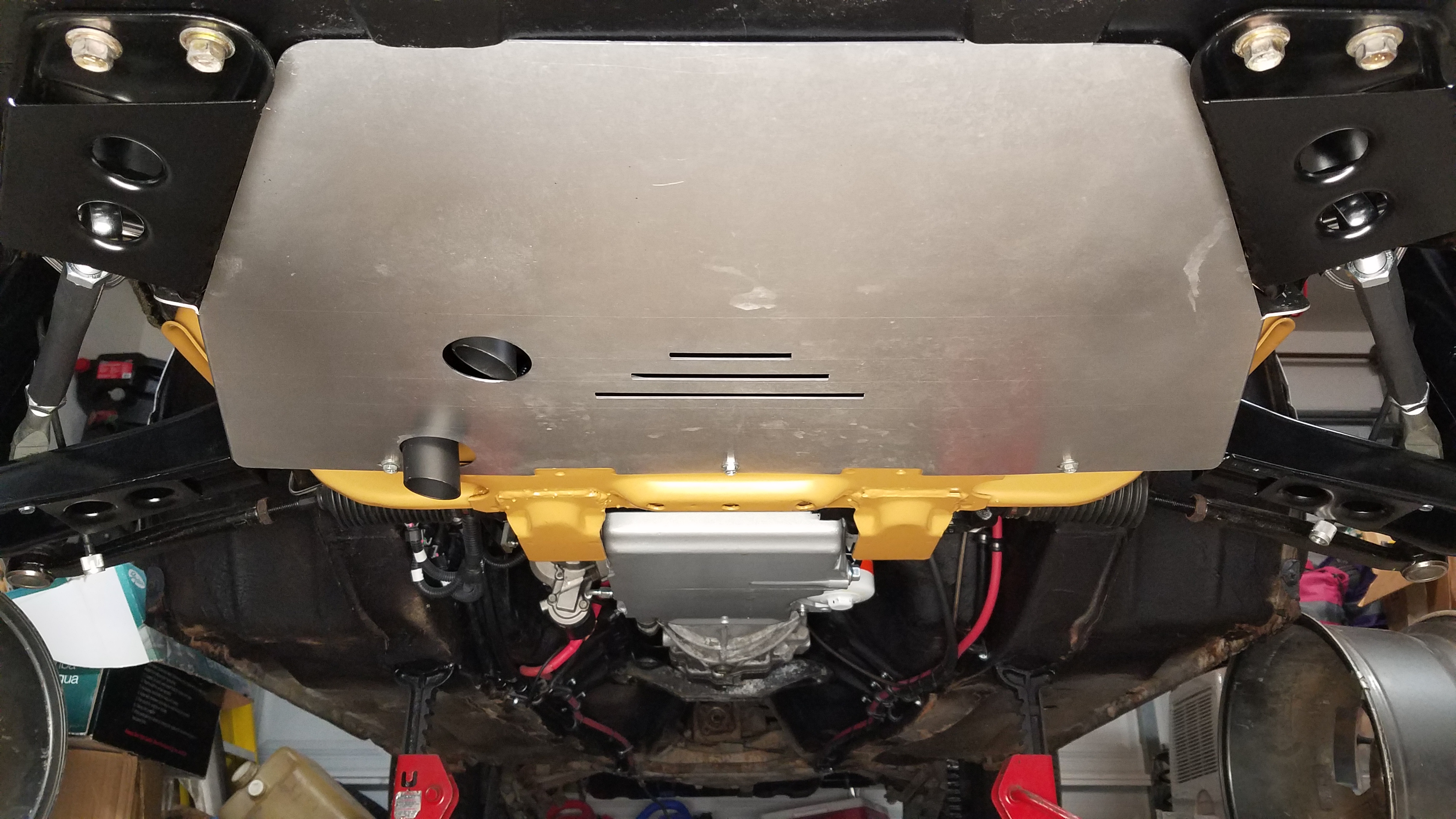
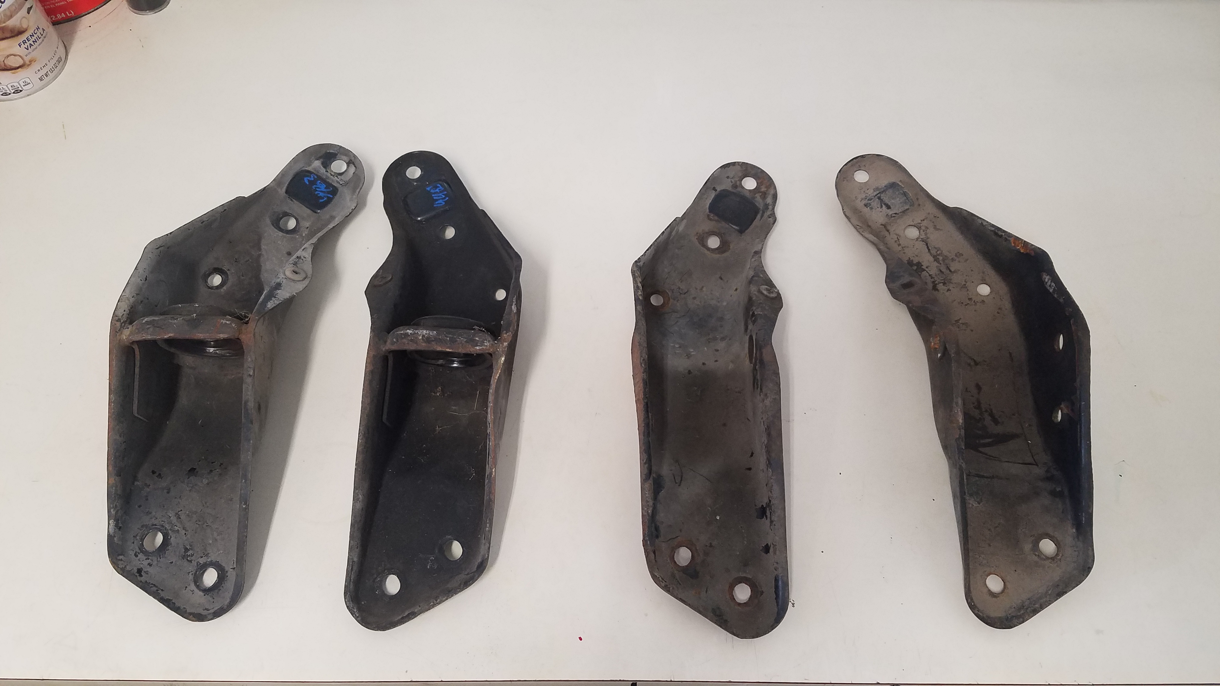
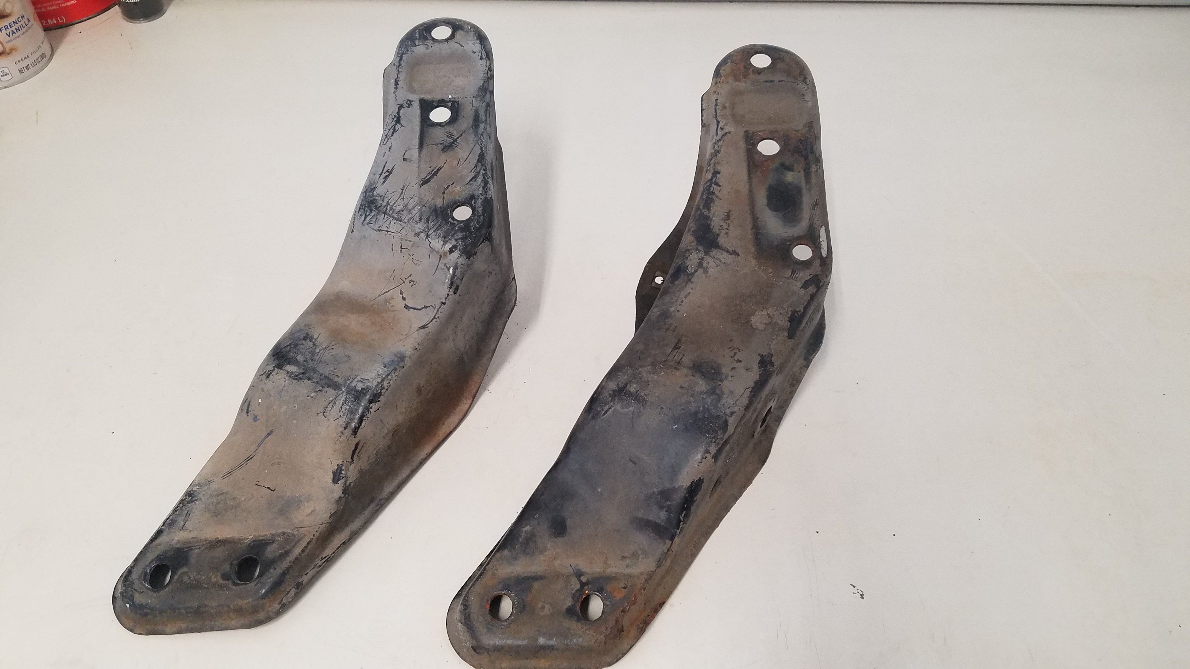
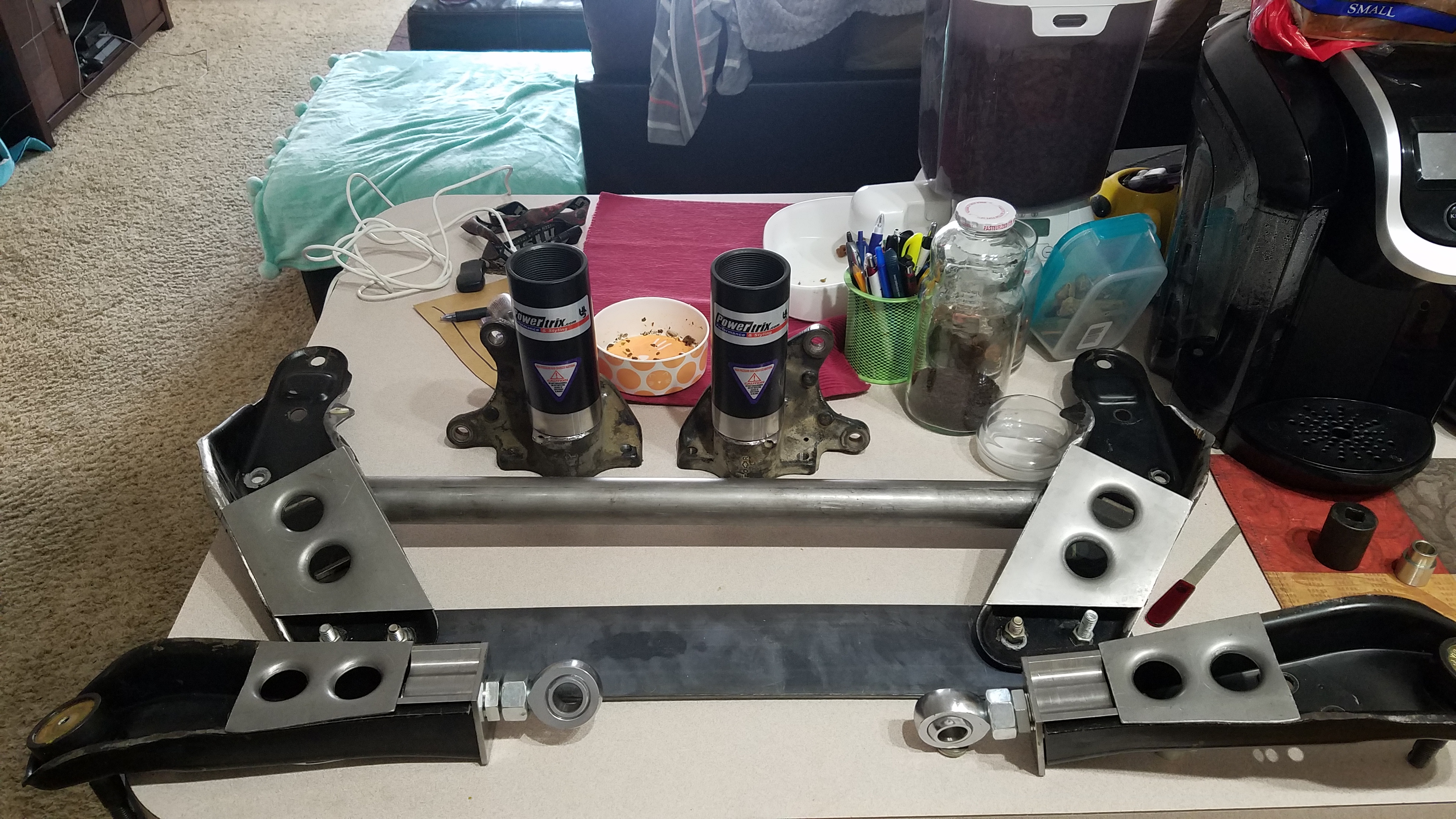
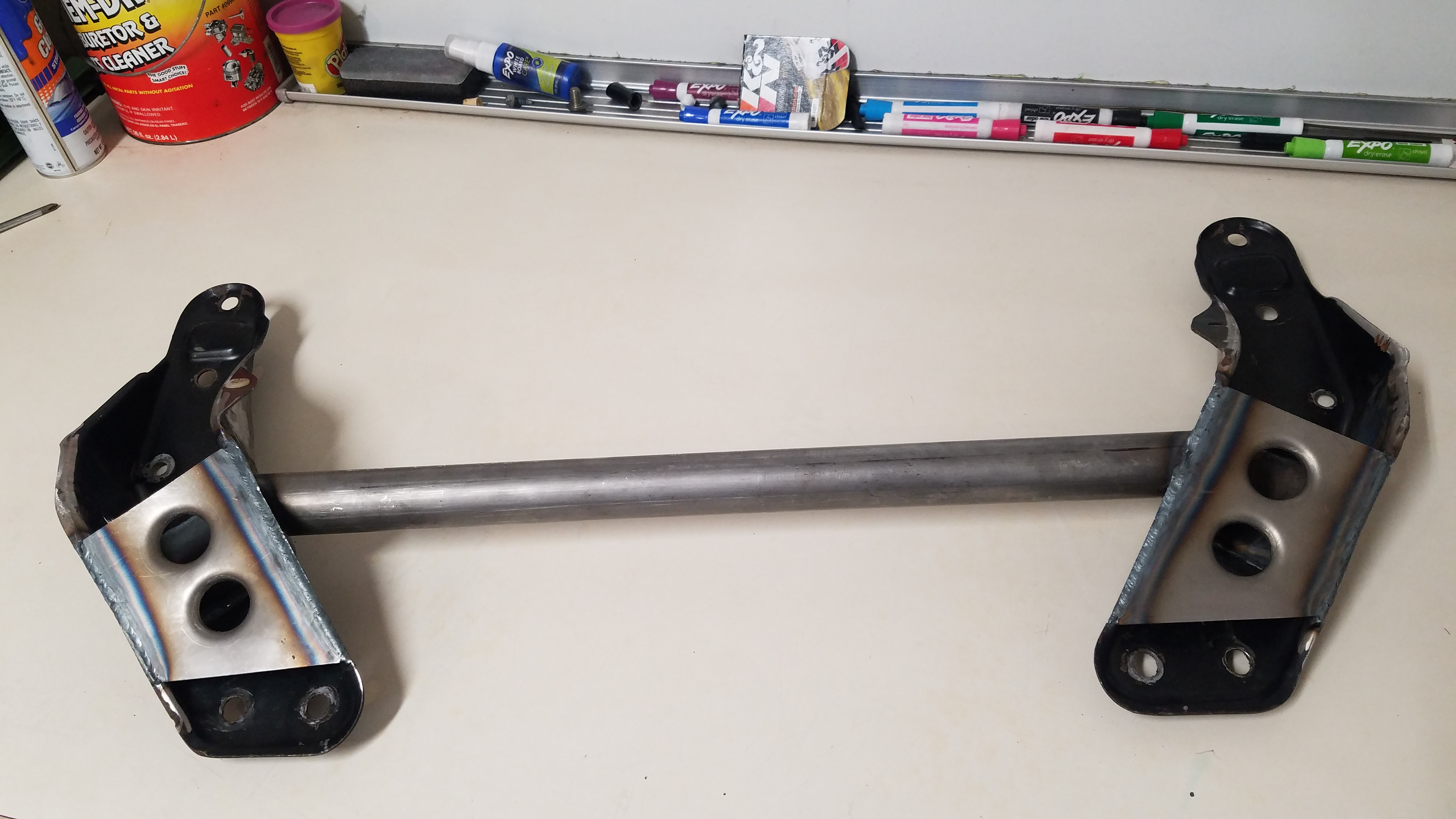
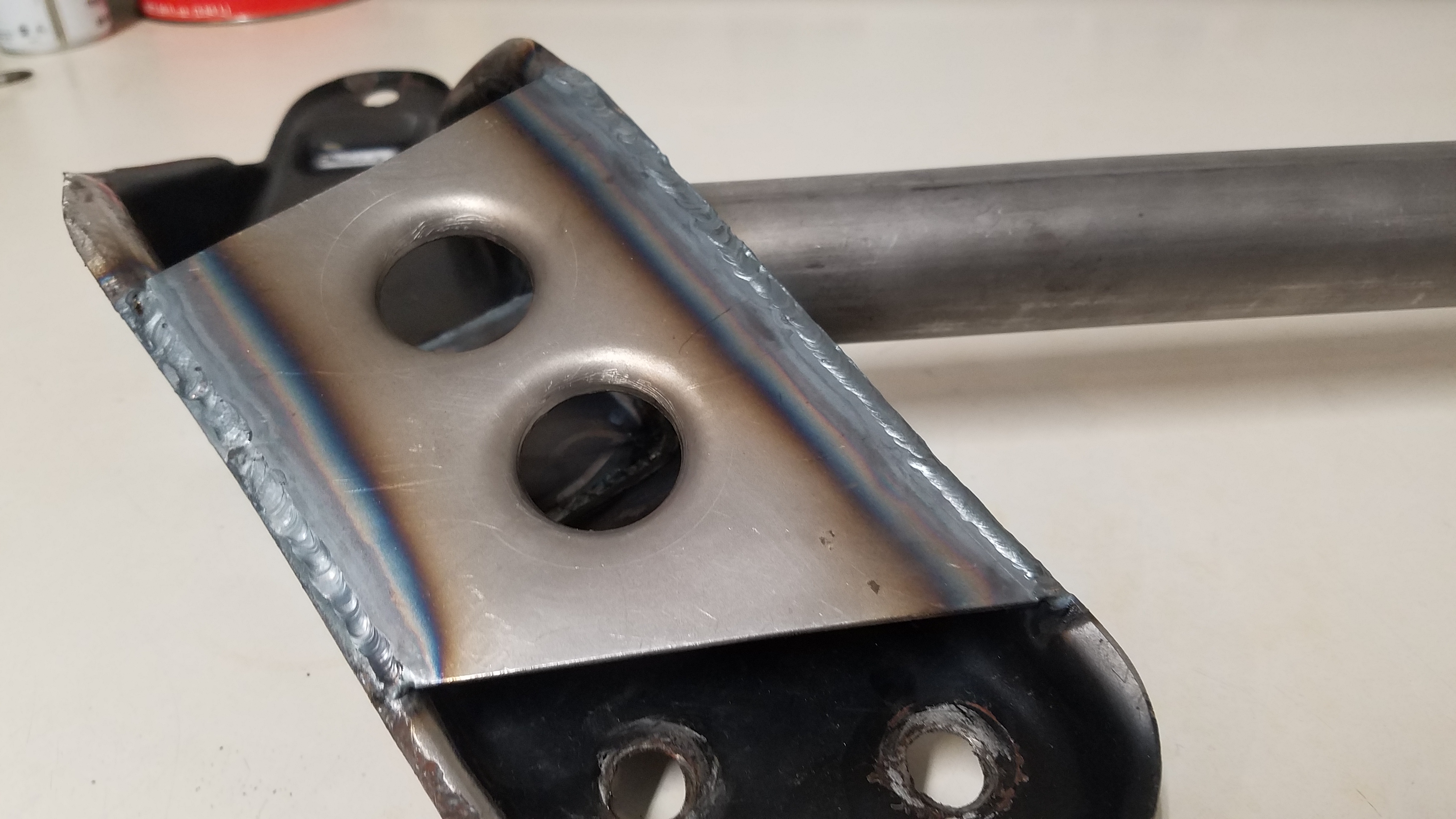
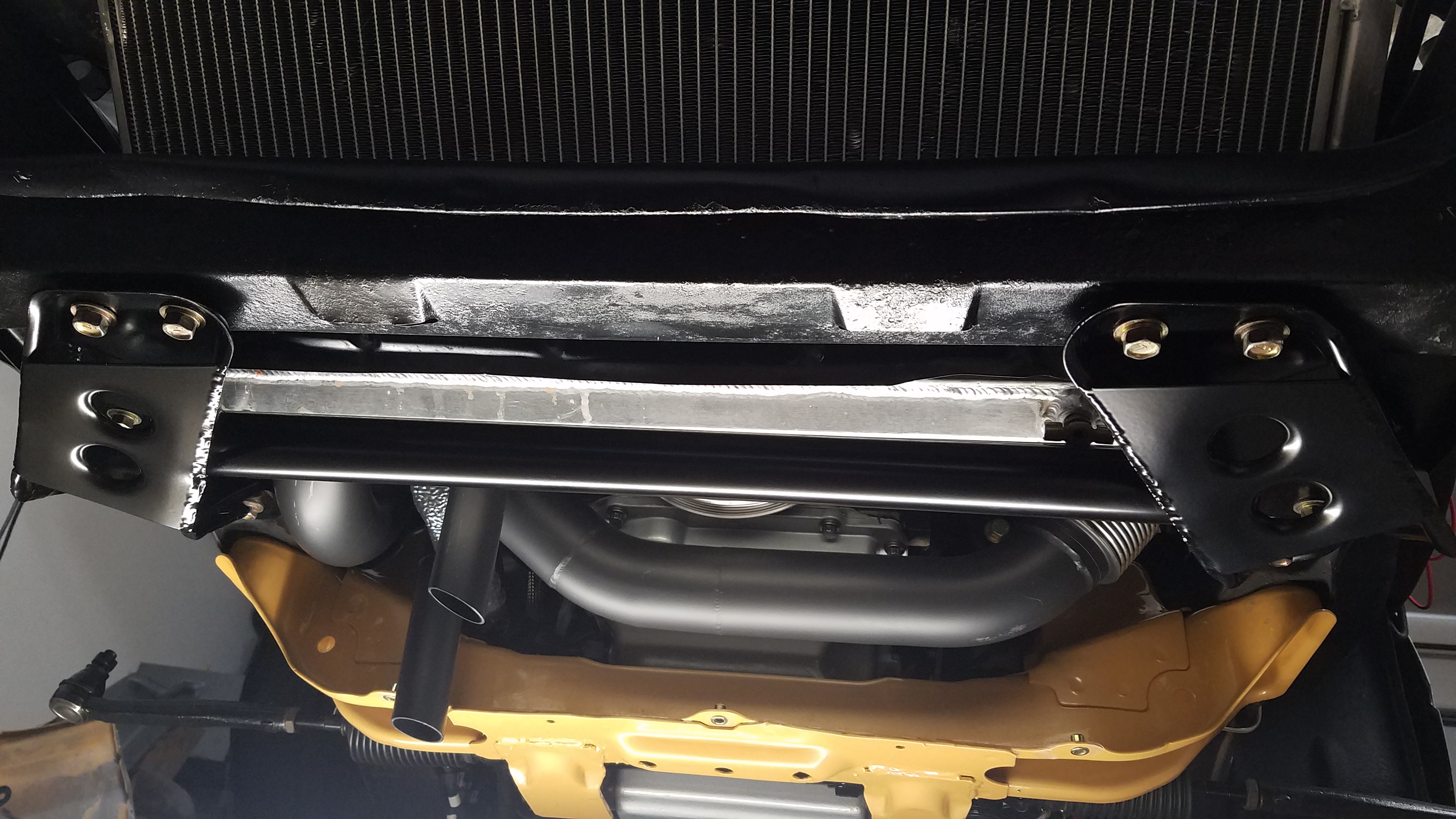
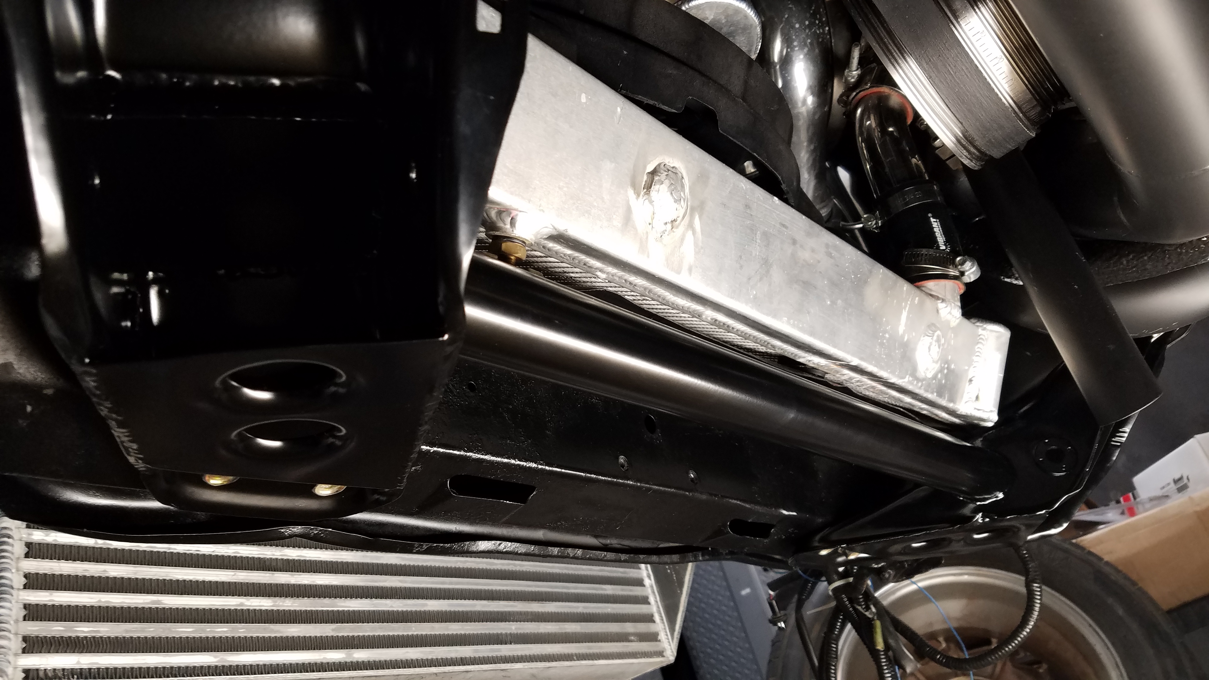
I began to tackle some suspension modifications as well. Starting with upgrading to the the later style Z31 tension rod brackets. Unfortunately I discovered that my champion 3 row radiator makes contact with the both versions of the (early & late) tension rod brackets. Before now I personally hadn't seen anyone else run into this issue. Wanting to see if this was a isolated issue, I compared my findings with another Z31 local to me. Our radiators have a 4 year difference between our date of purchase. But we both have the exact same issue. If you own/plan to purchase a Champion 3 Row Z31 radiator you should take note of this issue. Because it'll likely puncture the radiator end tank over time. In order to correct the issue I modified tension rod brackets to clear the radiator. After this l made my own "Power Brace". For those that hadn't heard of this, it's a brace that ties your tension rod brackets together. Thus adds chassis stability, improved handling & transient response. Dimpled gussets were added to "box" in the tension rod brackets for additional strength. The power brace was finished off by being powder coated.
-
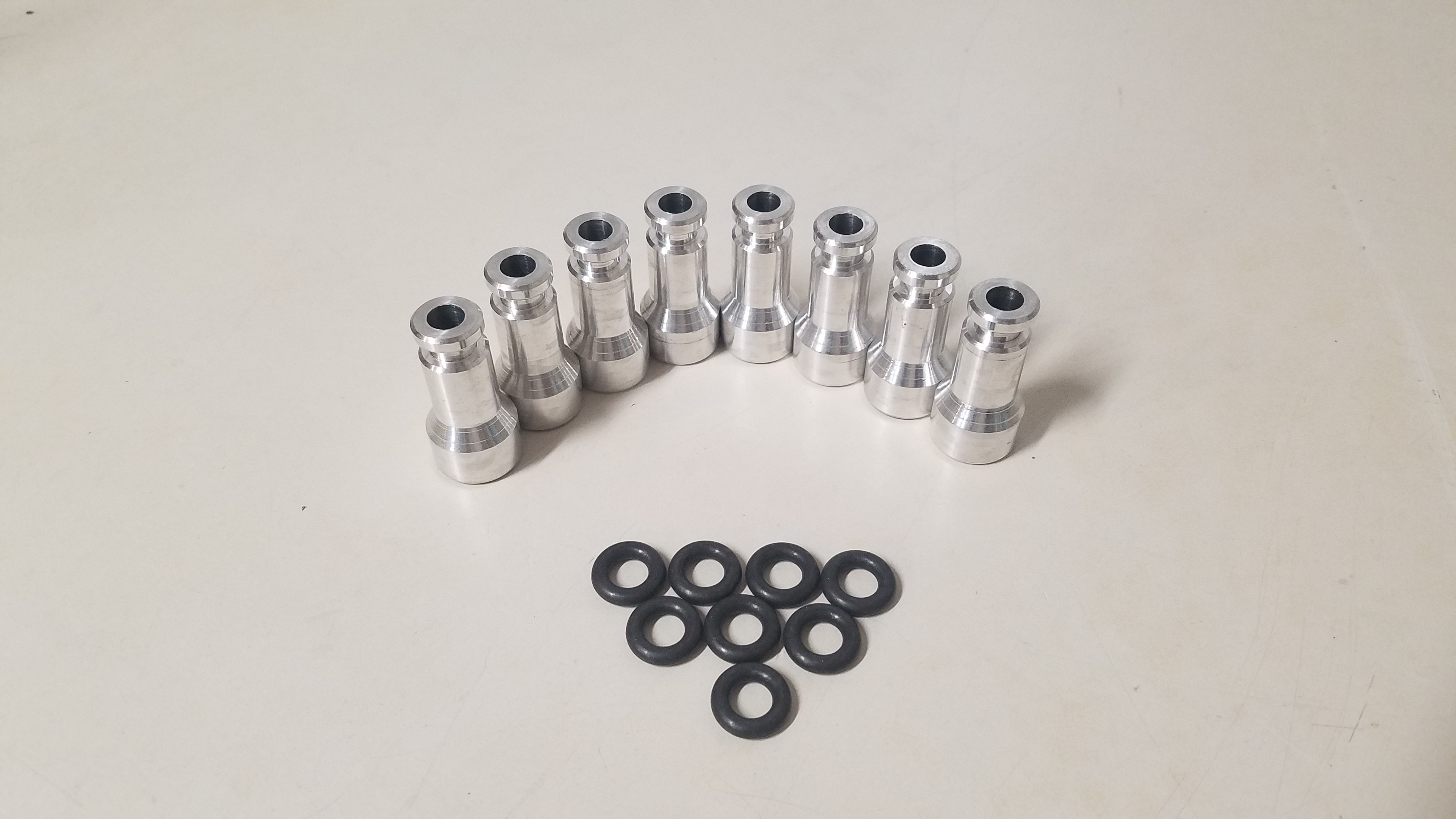
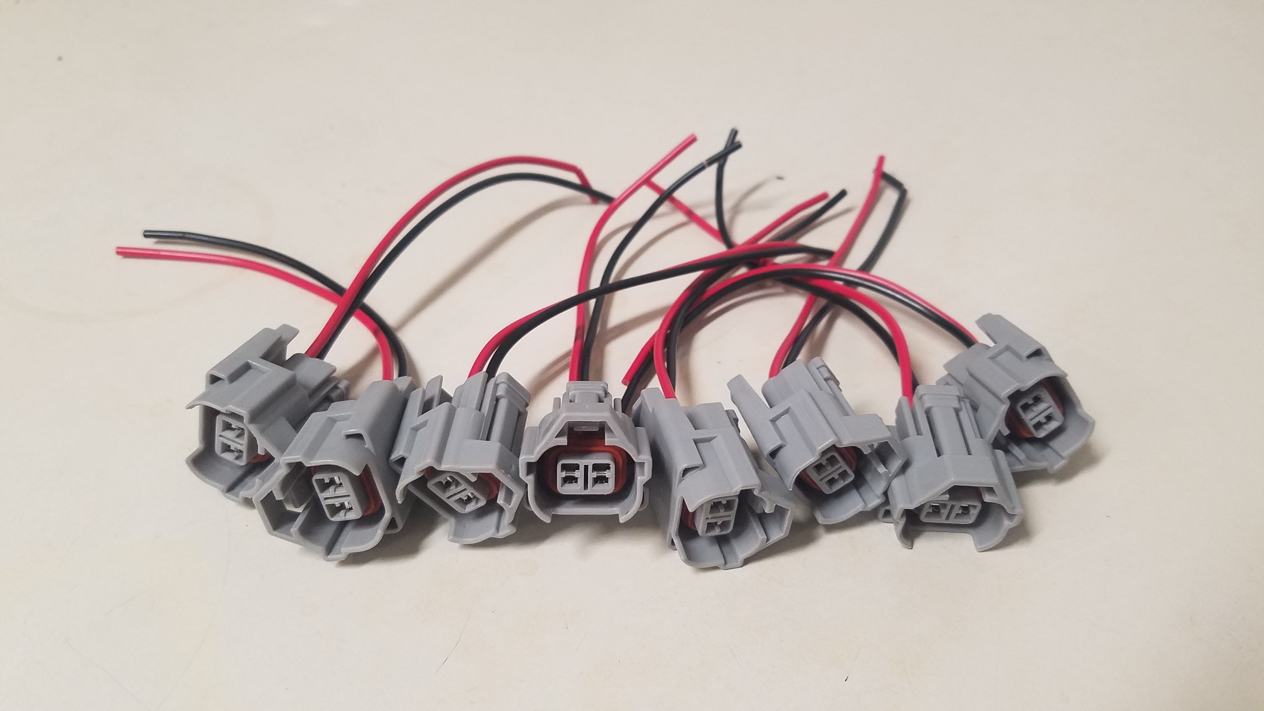
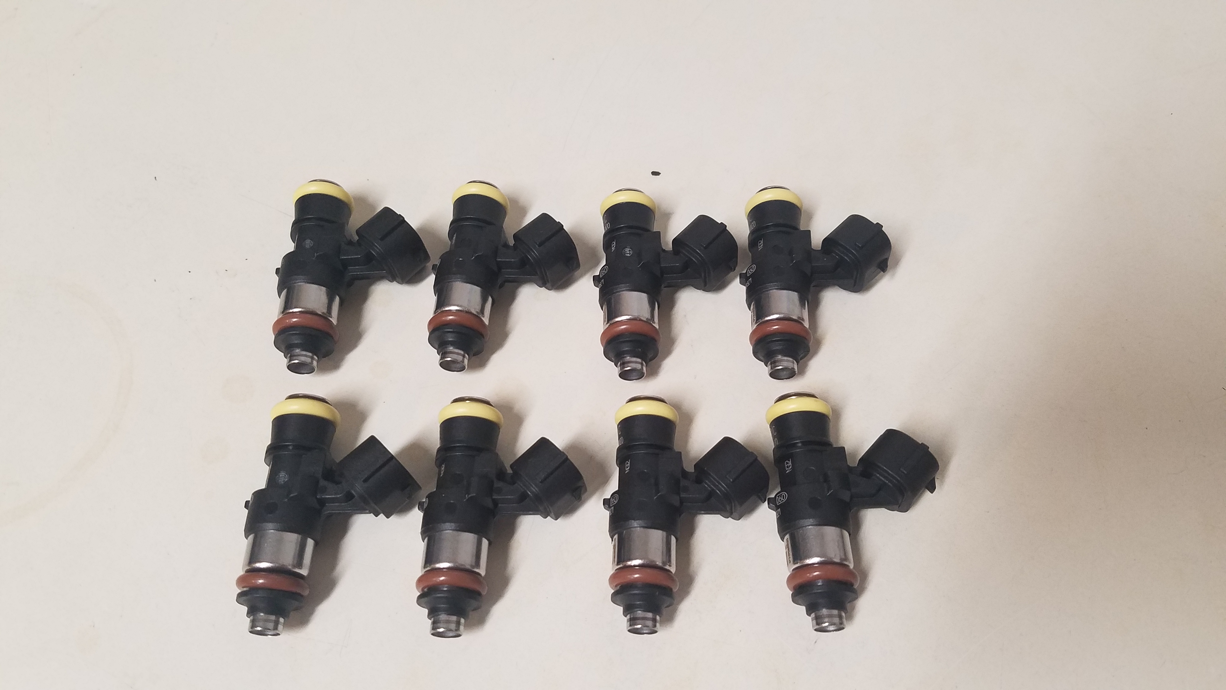
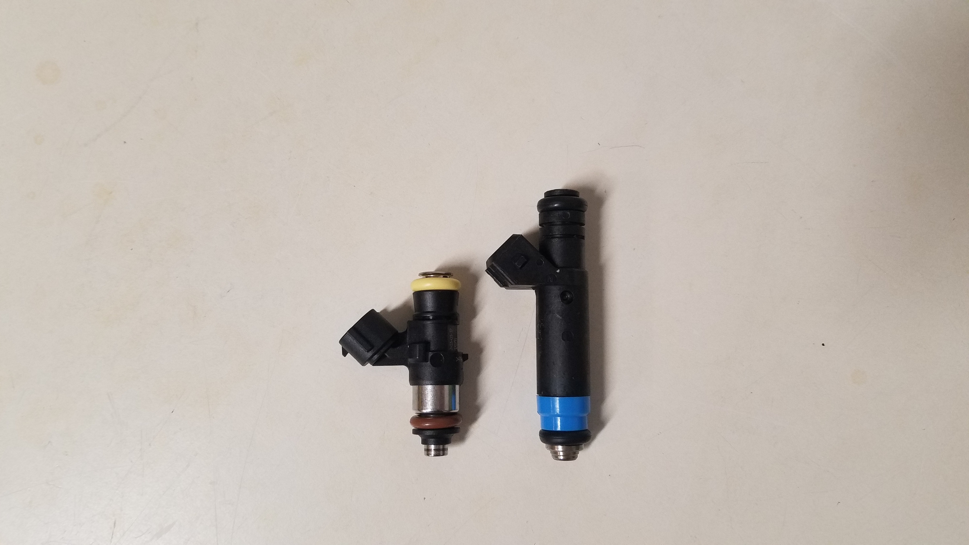
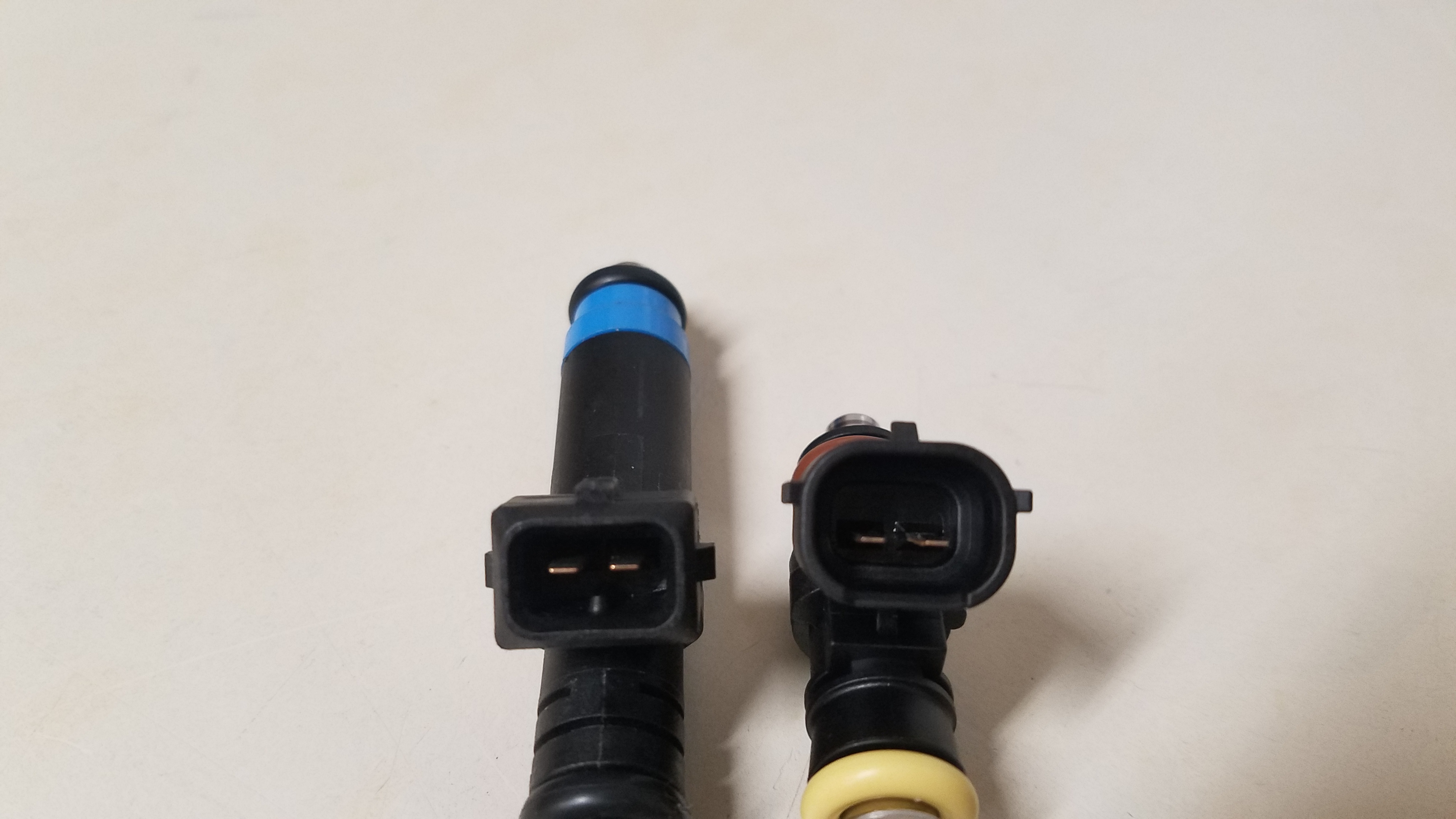
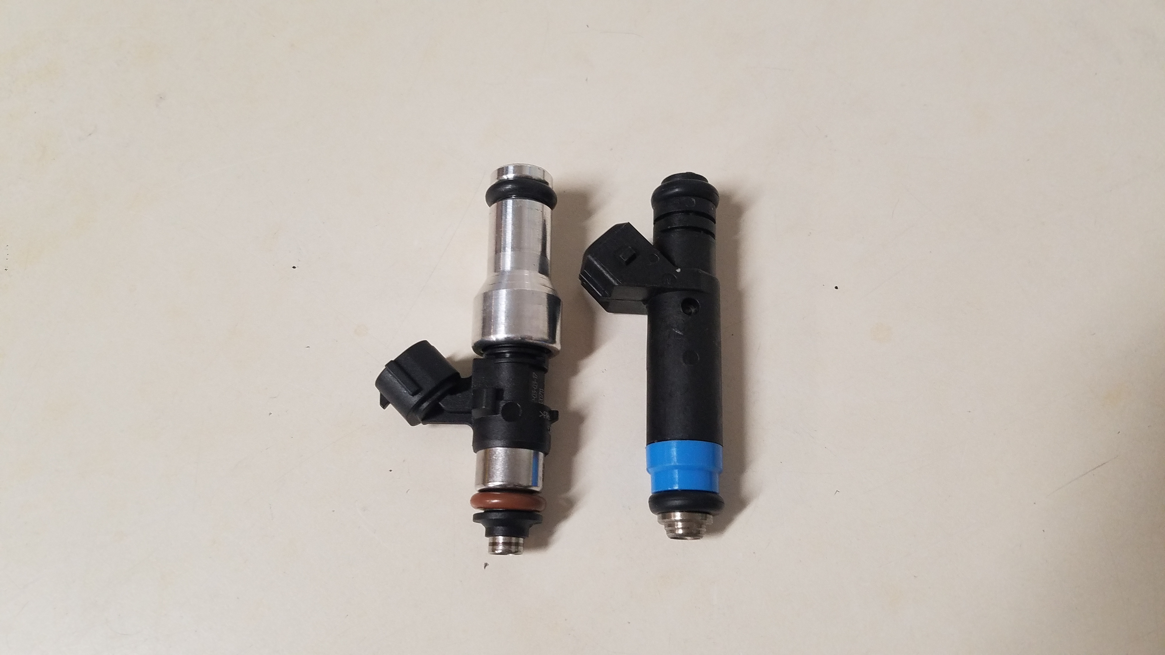
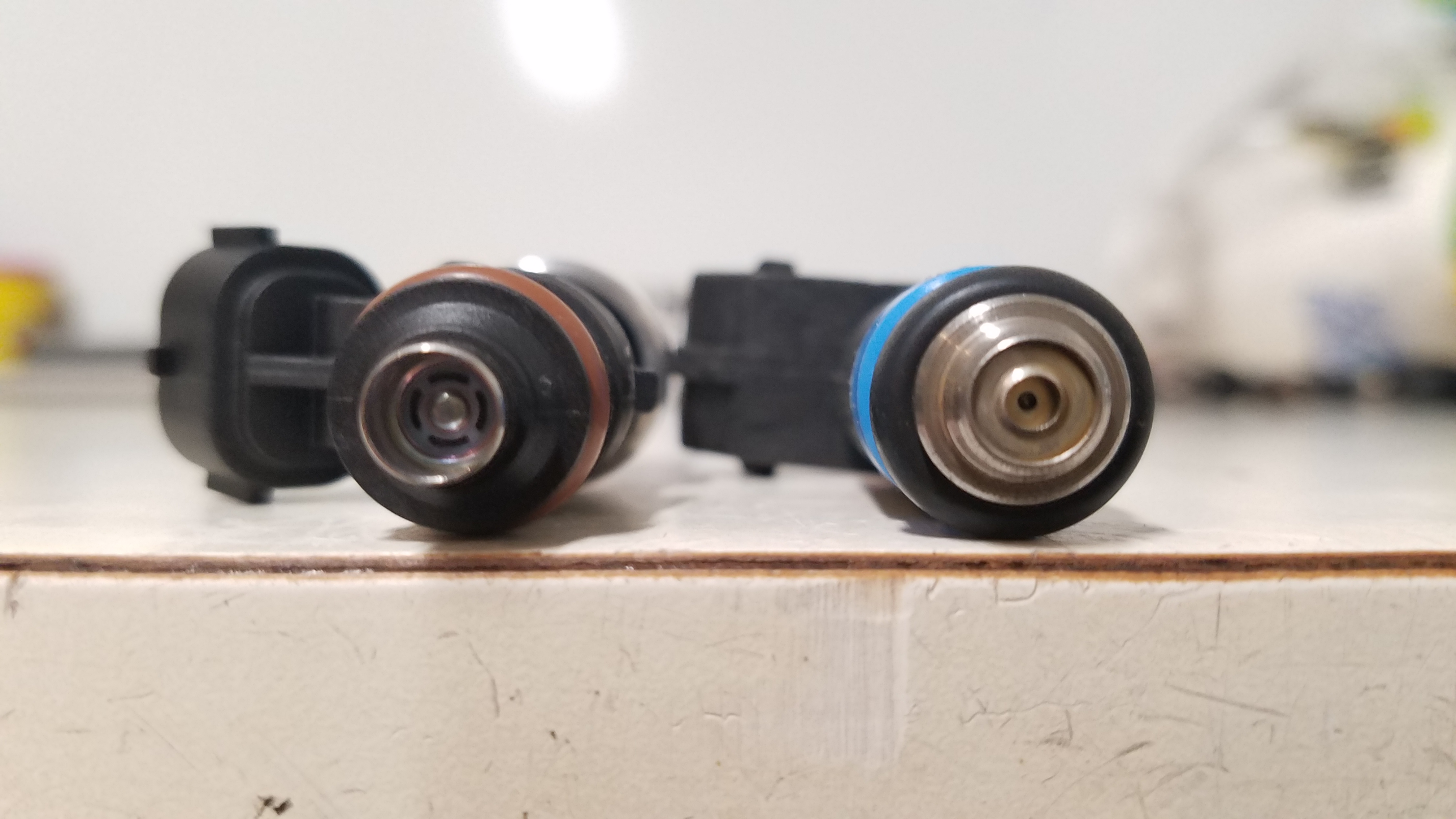
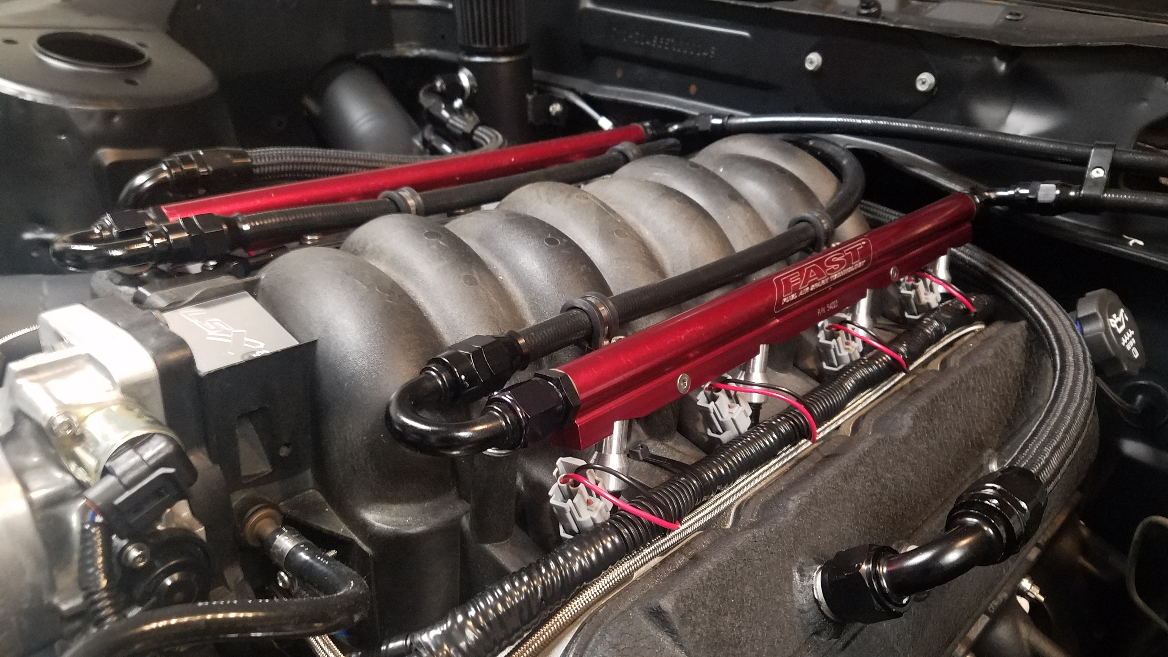
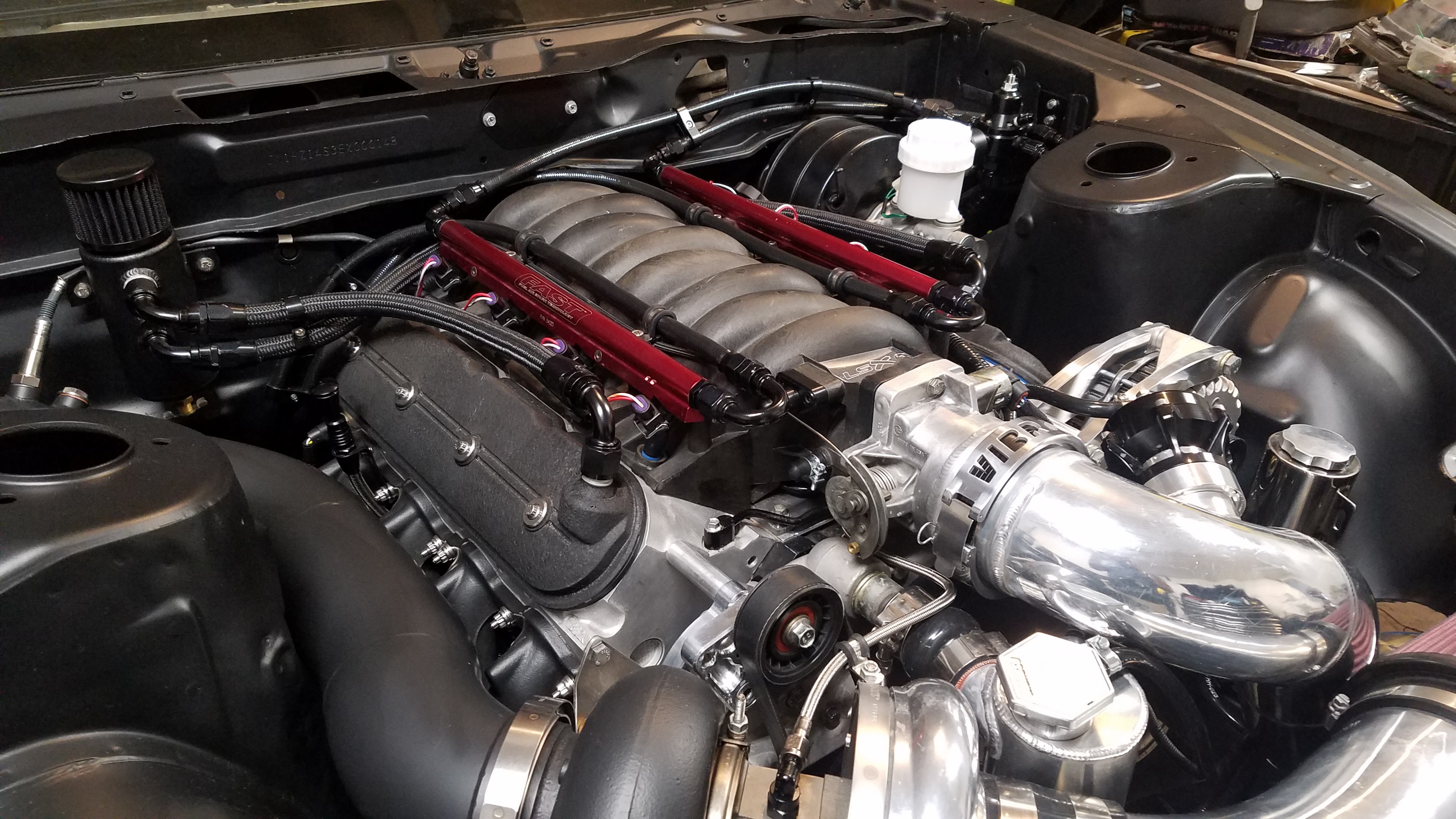
I also upgraded to 210lb injectors over the 80lb I previously had. I wanted the ability to run a slightly lower base psi while still having more room to grow if need be. To retain the clean look I opted to swap the injector connectors out instead of using bulky adapters. Also I'd like to give a shout out to Matt Happel aka denmah for sharing his sharing his tunes. This is the 2nd base tune of his I've used. These tunes made things 1000 times easier for me. Between the base tunes & the amount inspiration I've received from his content, I couldn't be more thankful. Here's a few pics of the 210lb setup along with a video of their 1st idle.
-
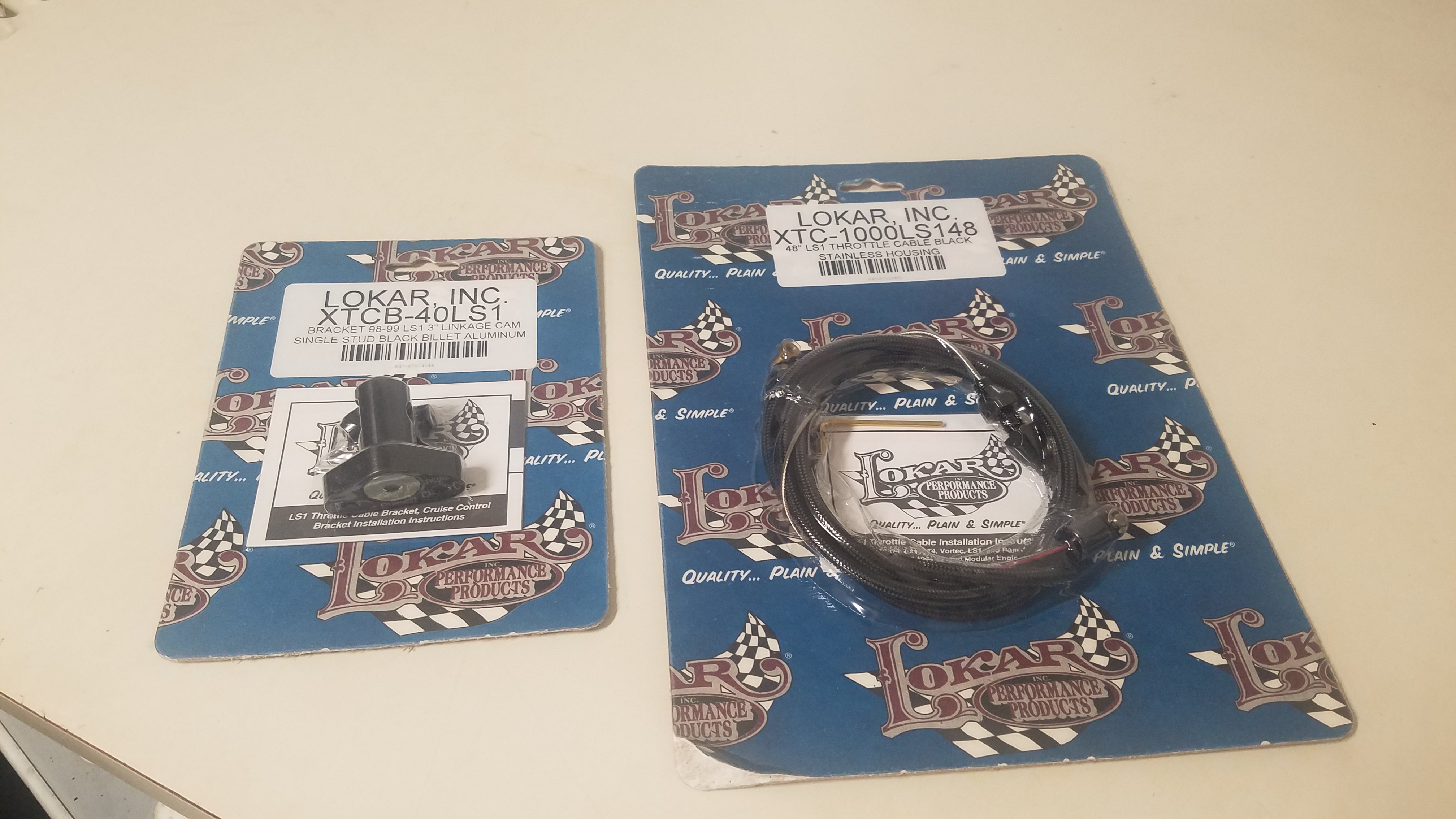
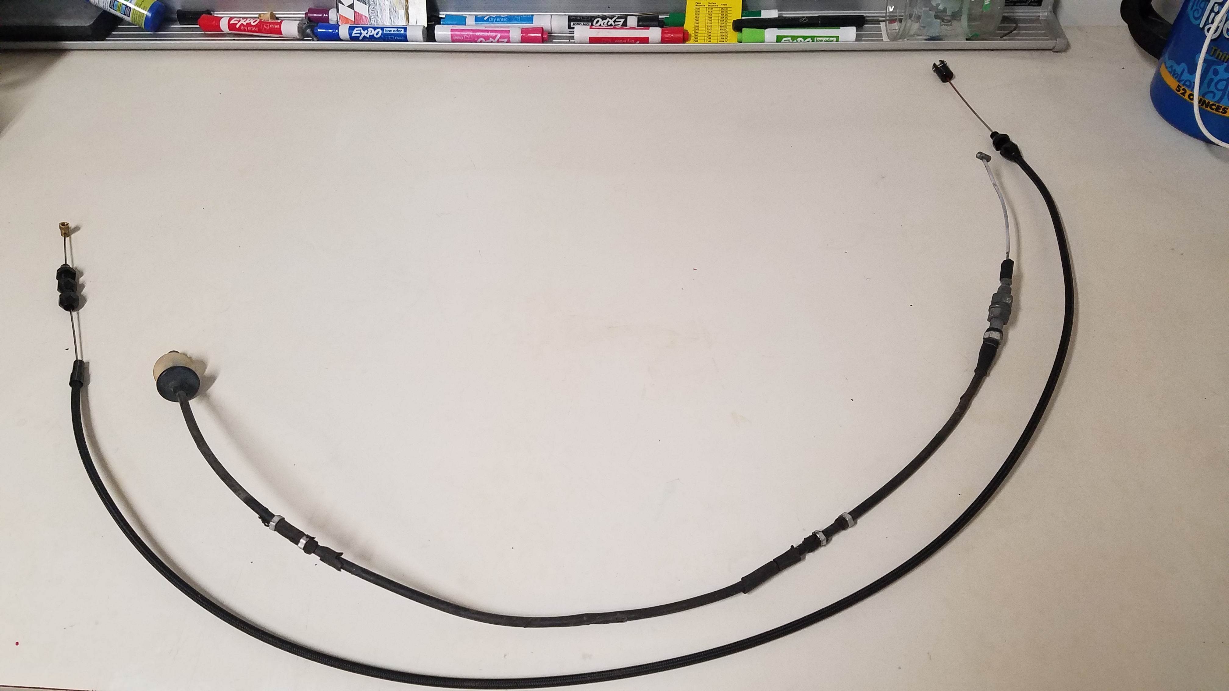
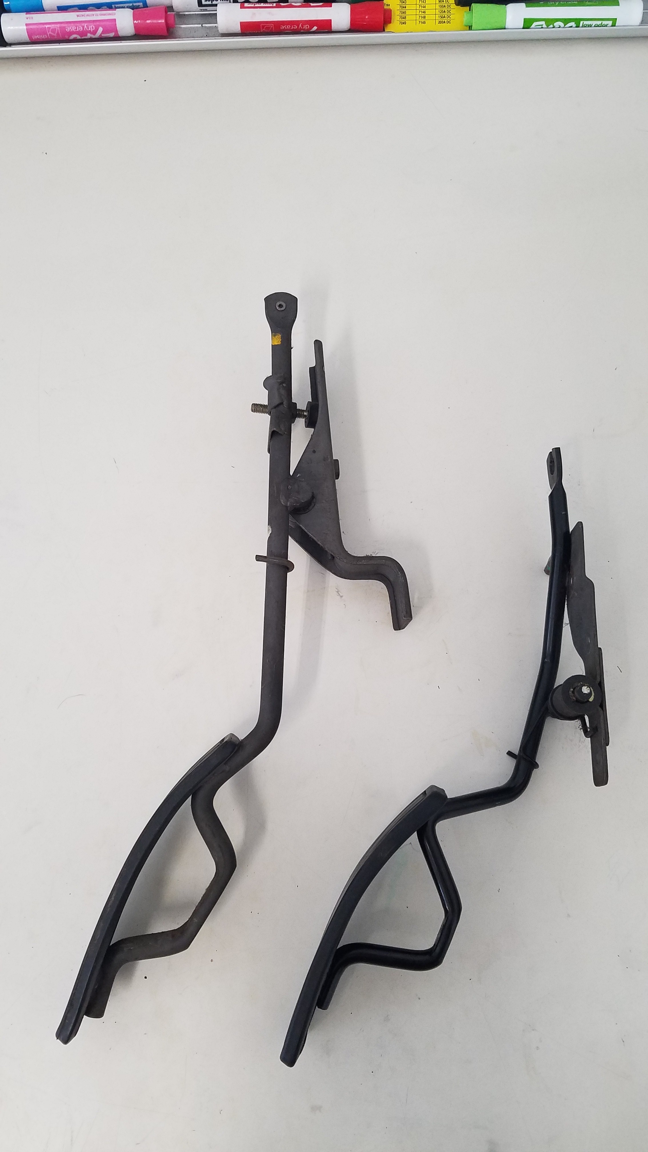
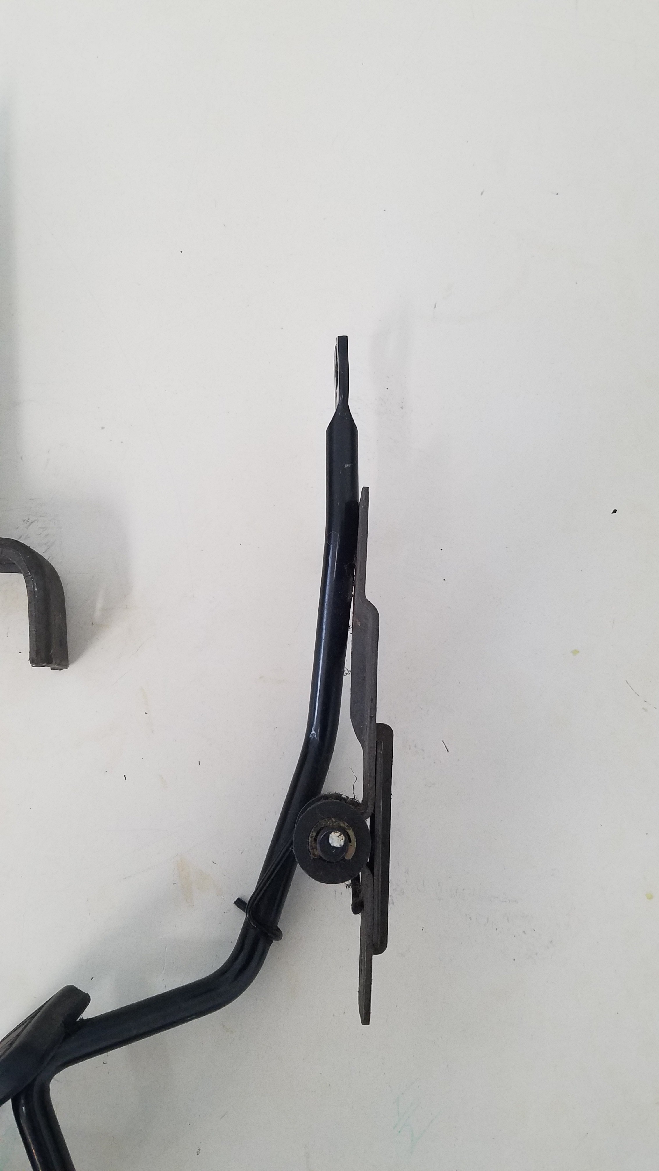
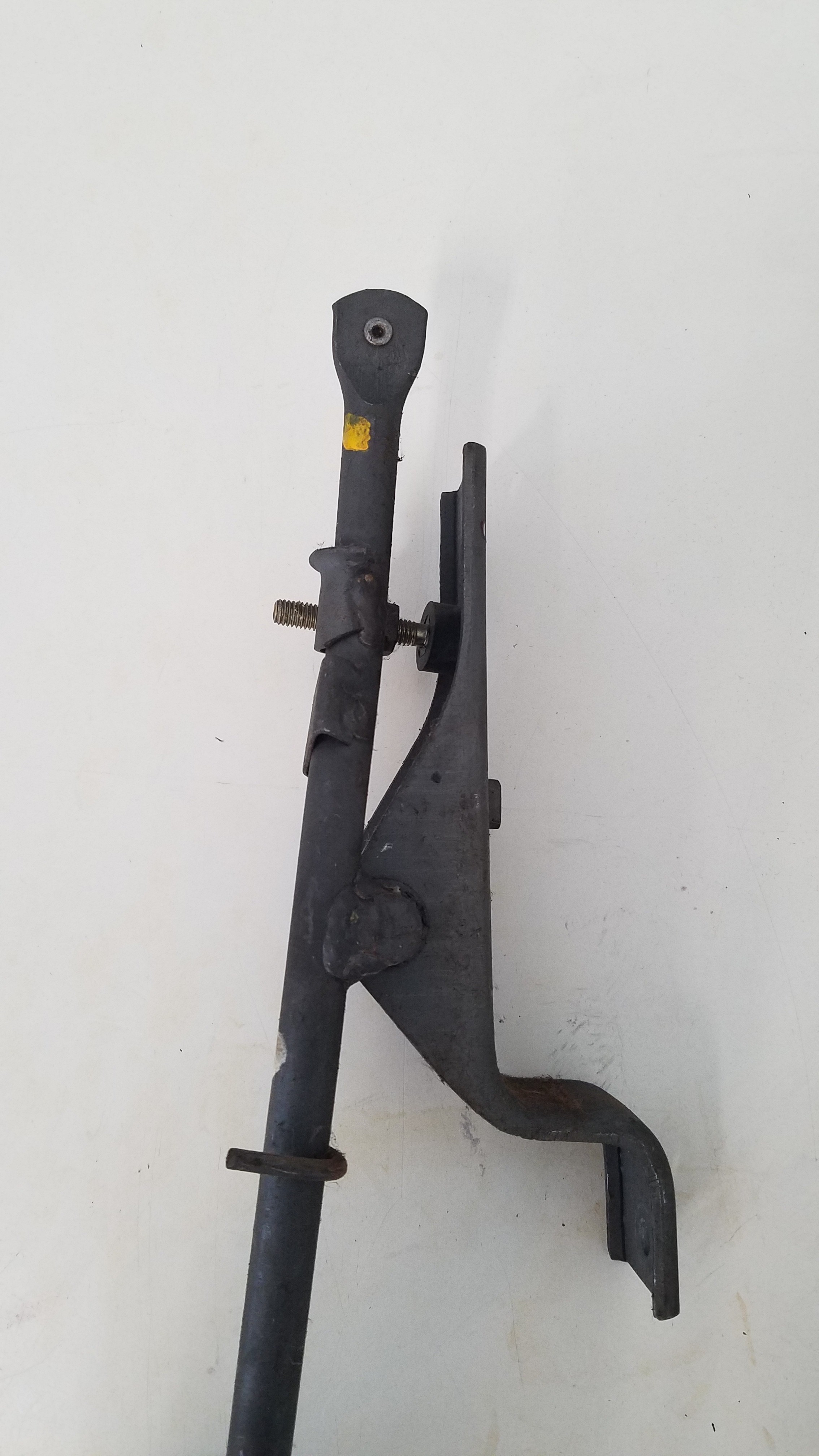
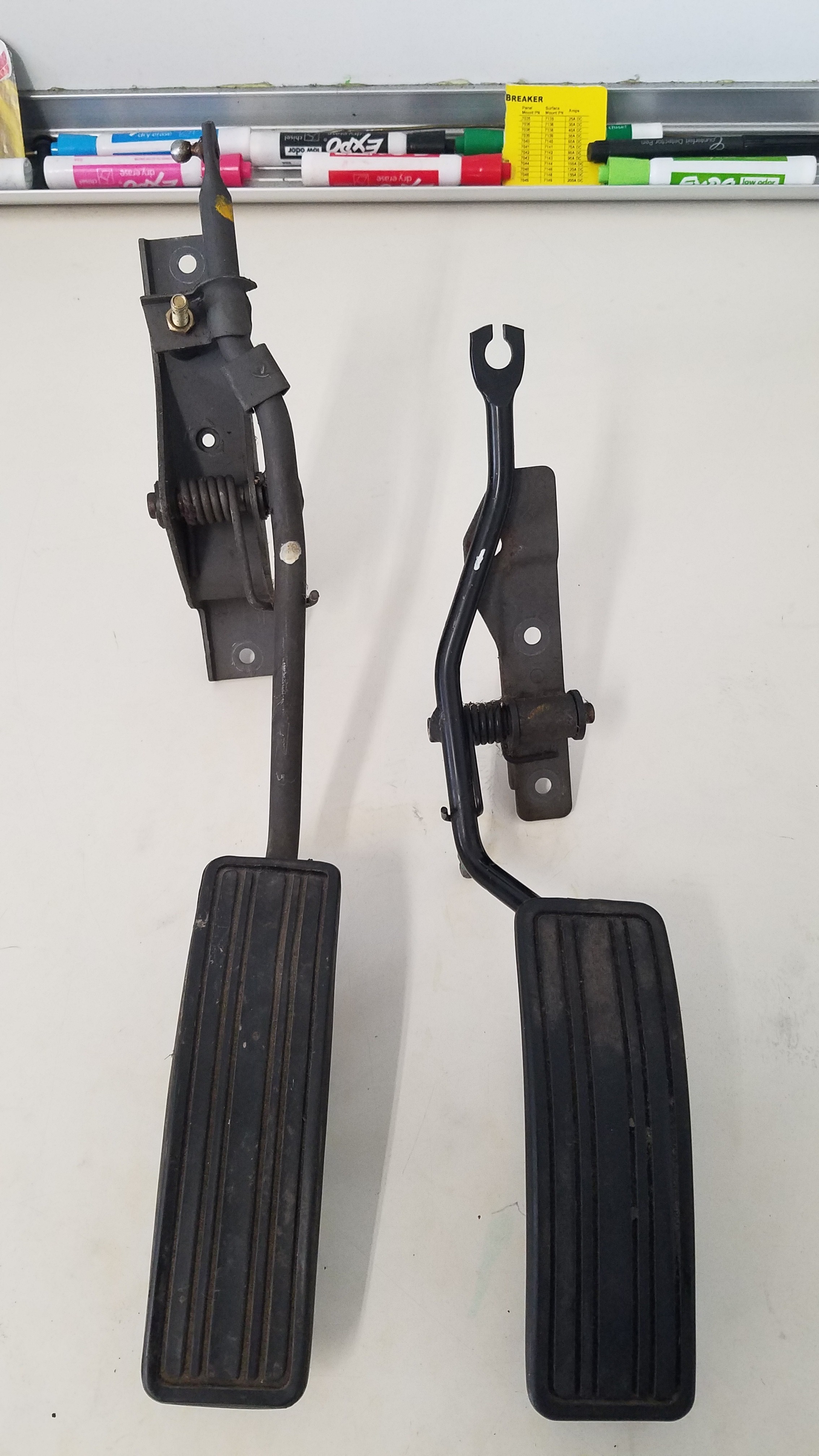
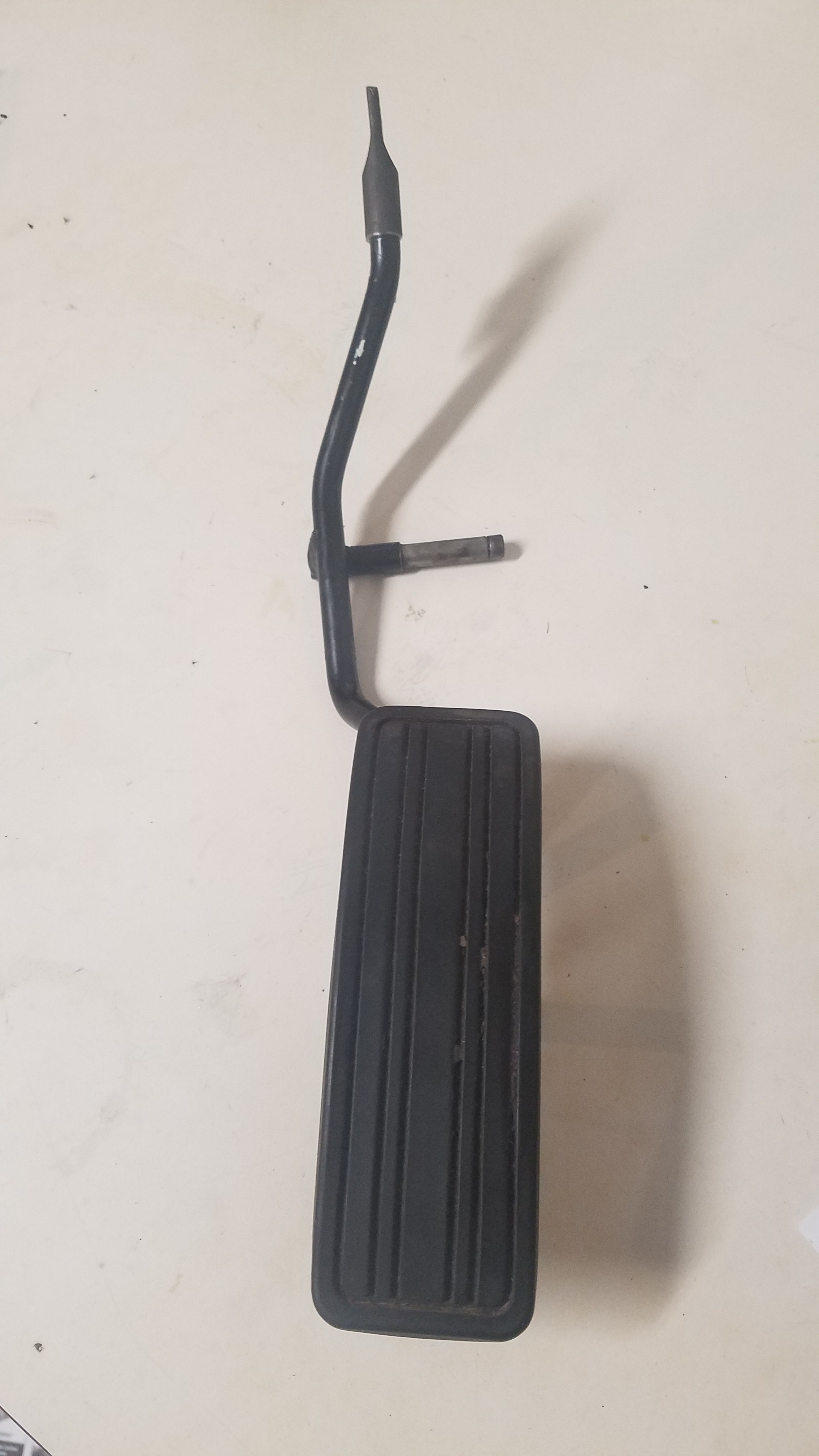
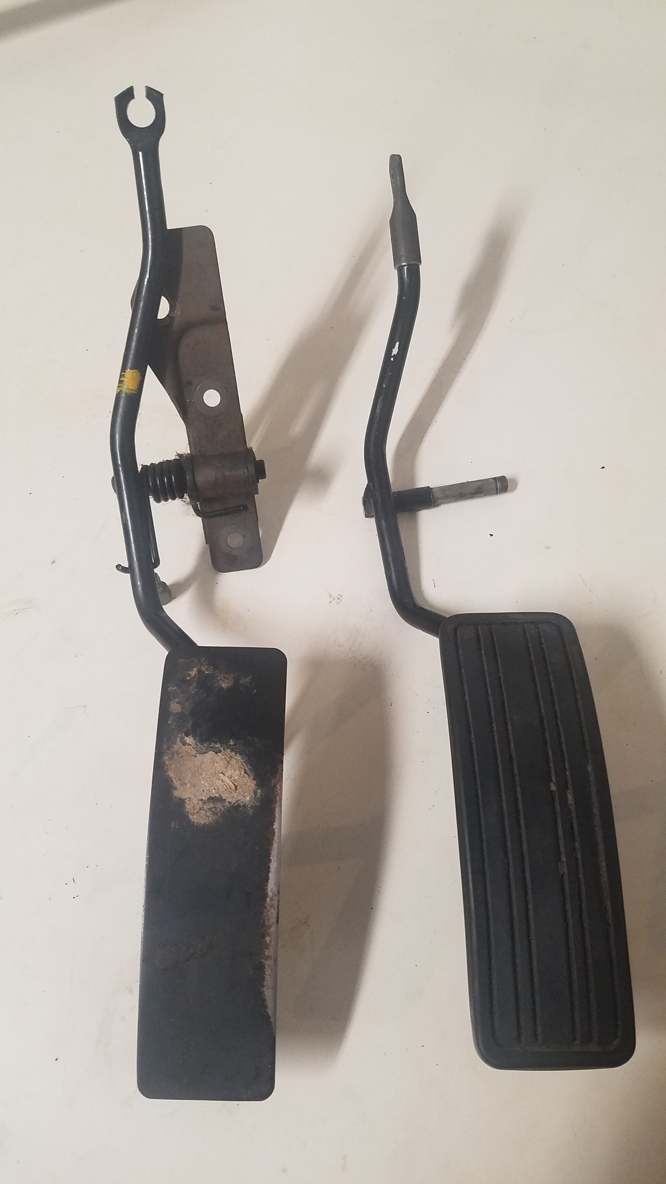
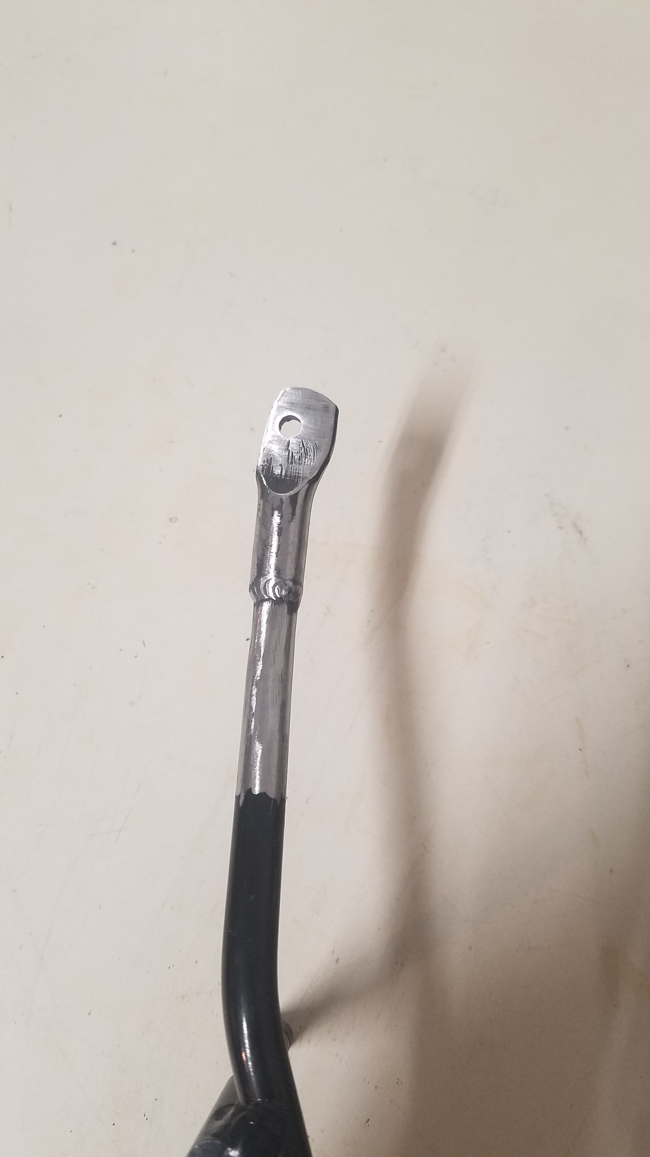
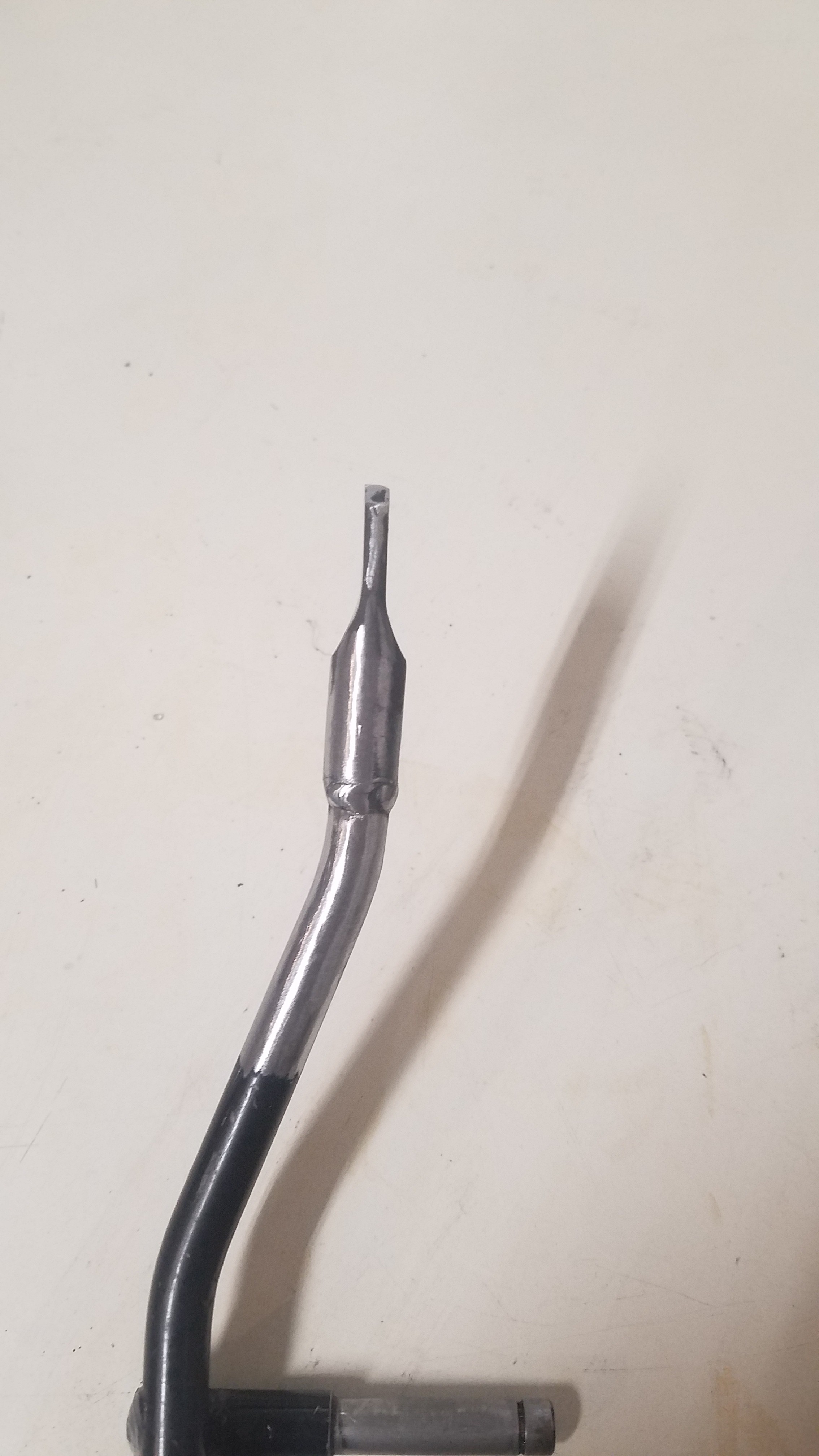
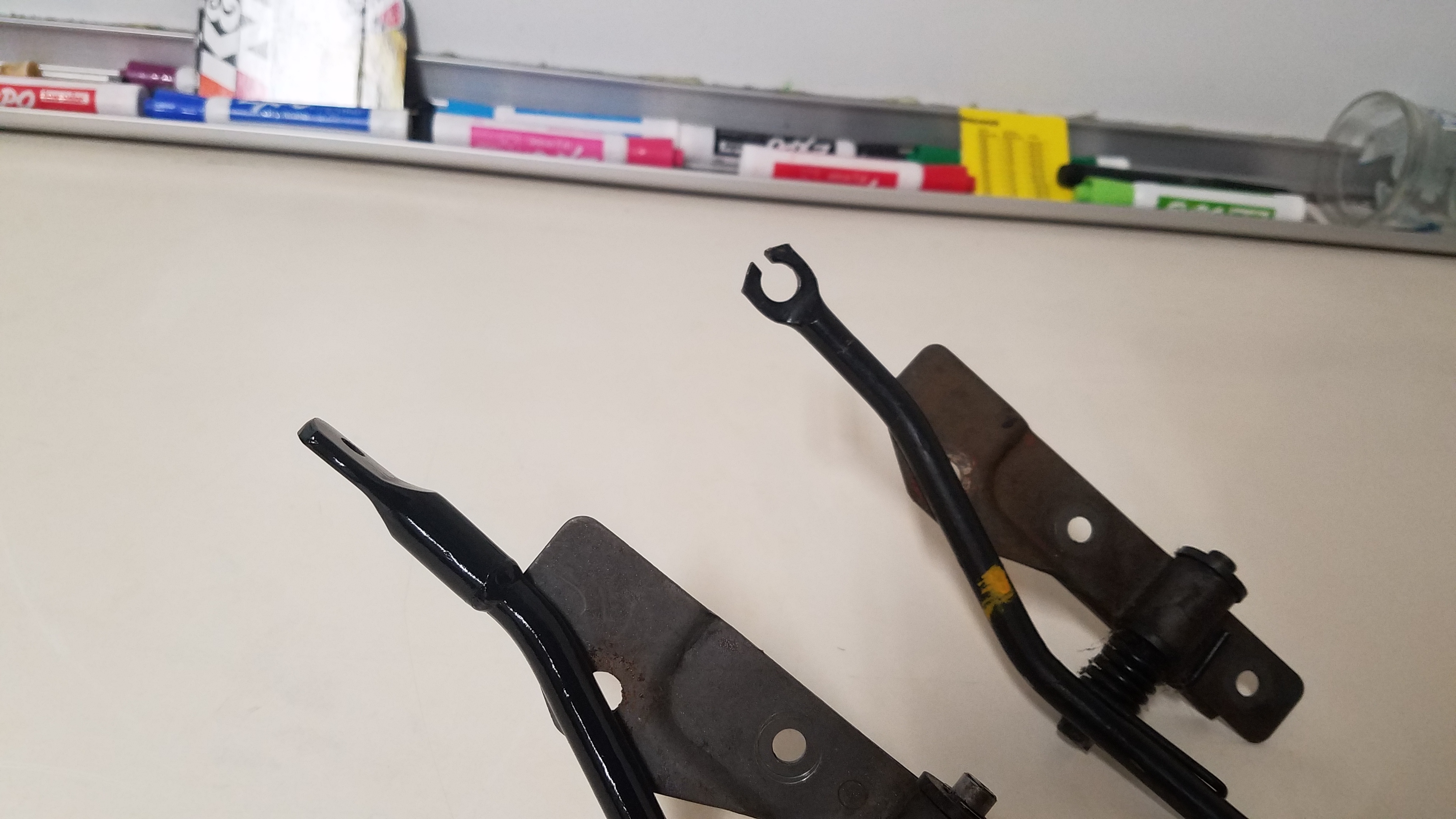
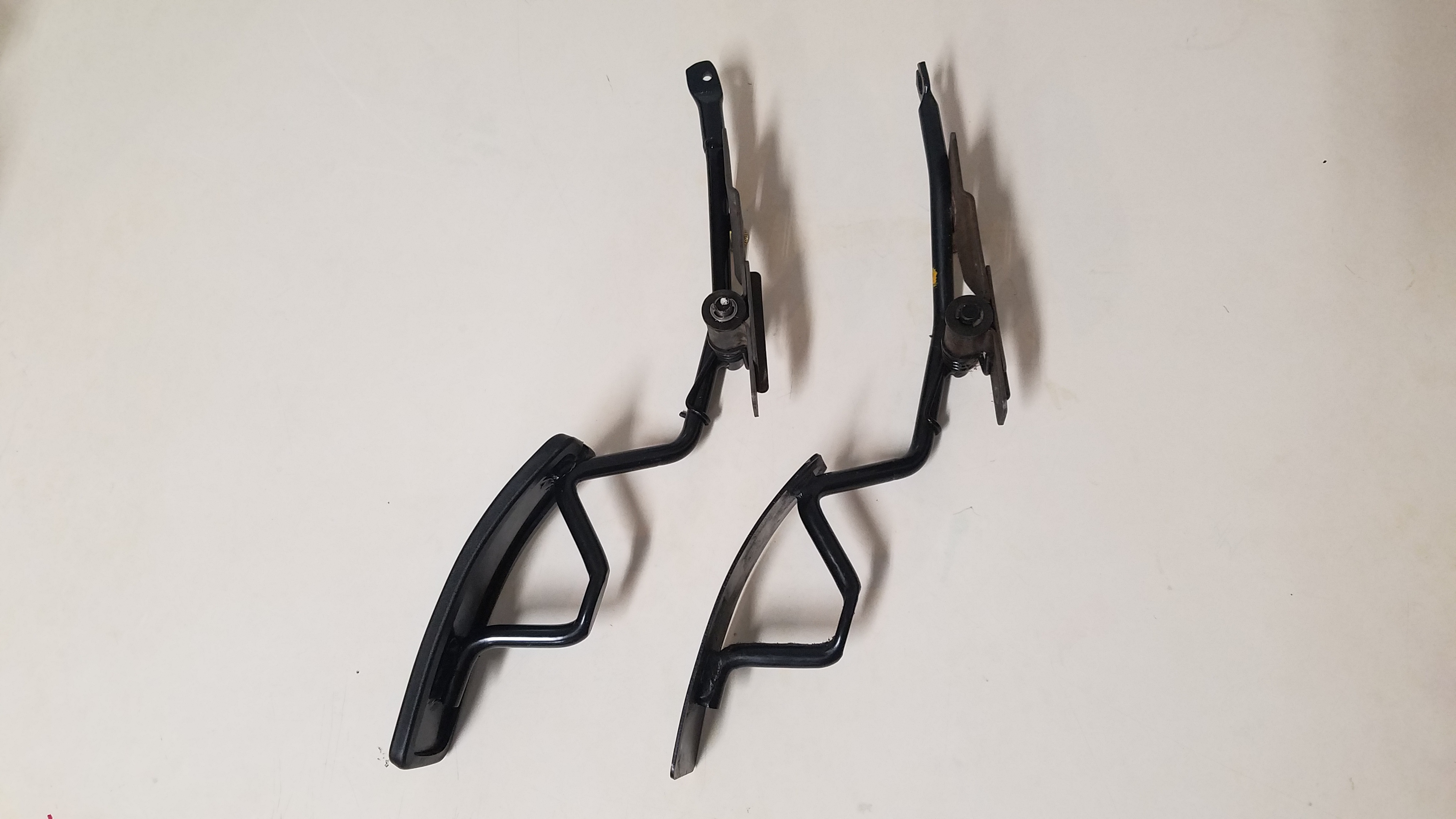
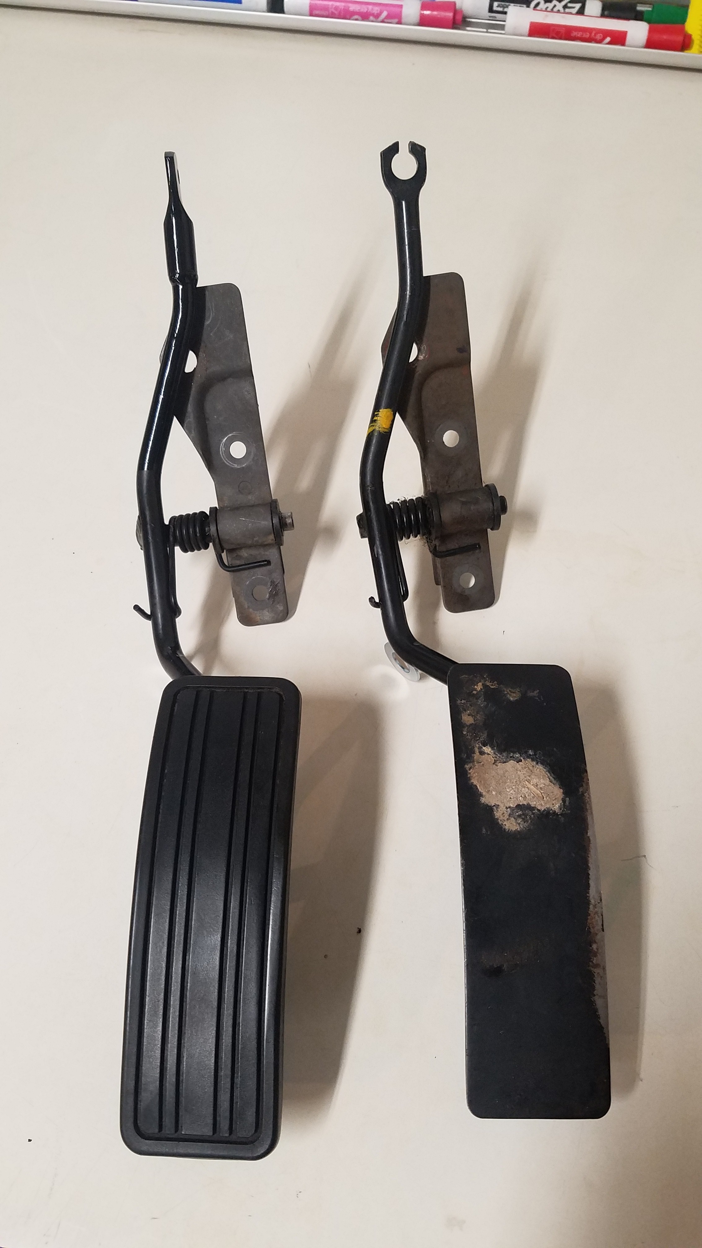
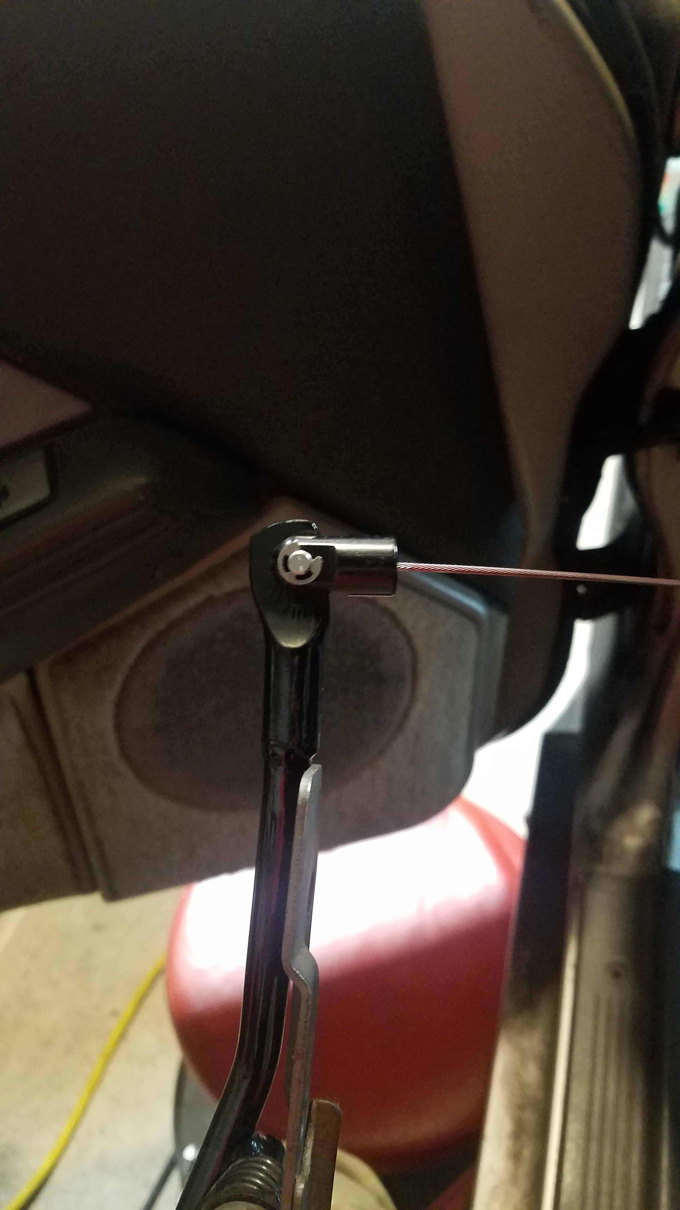
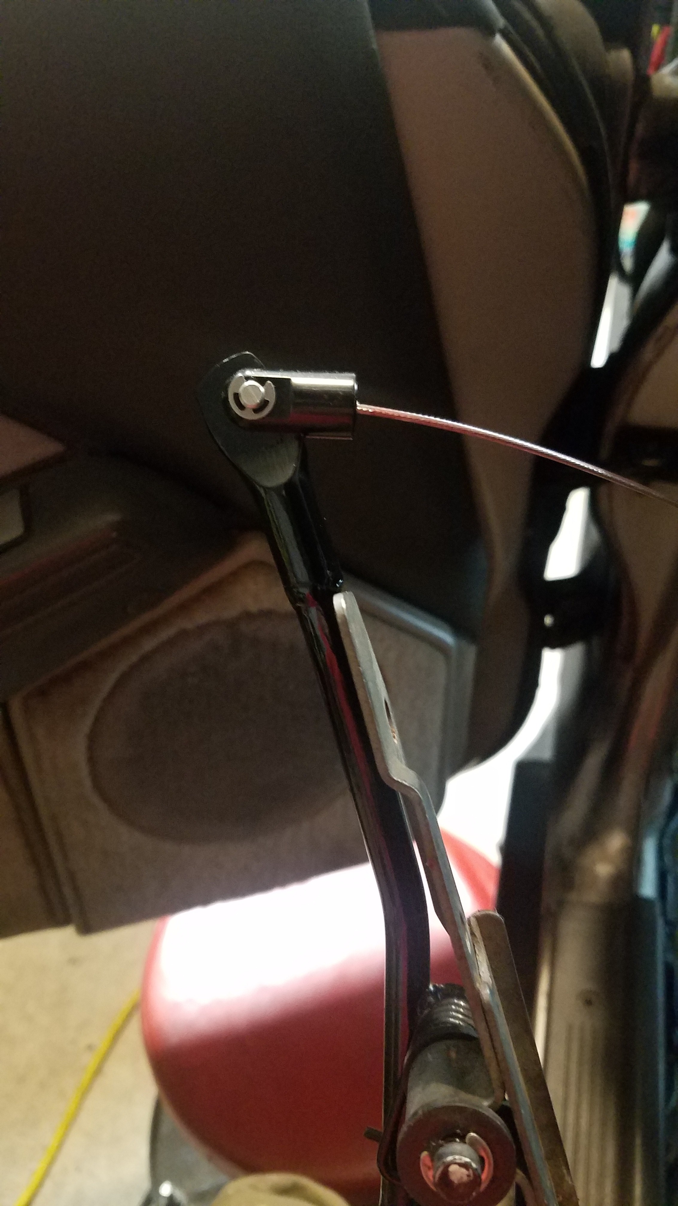
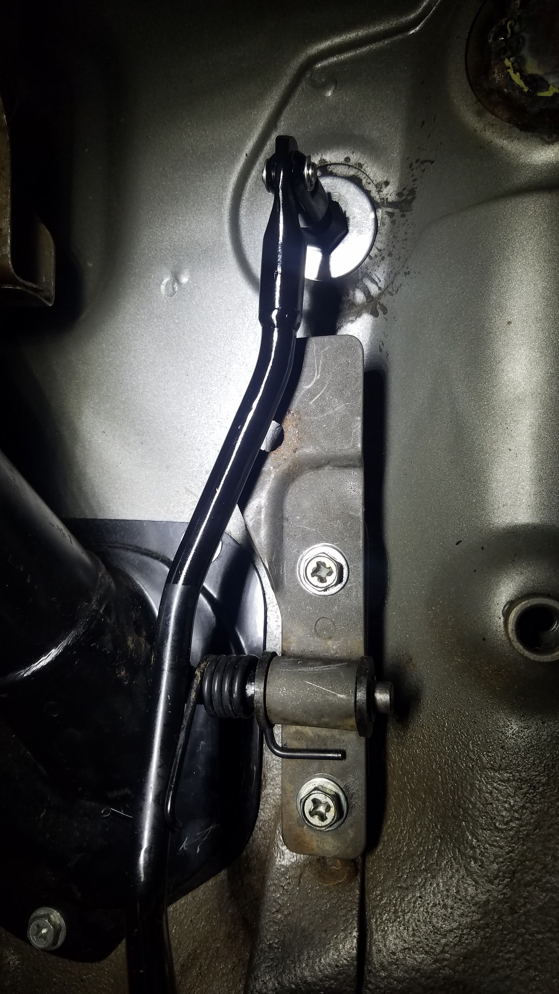
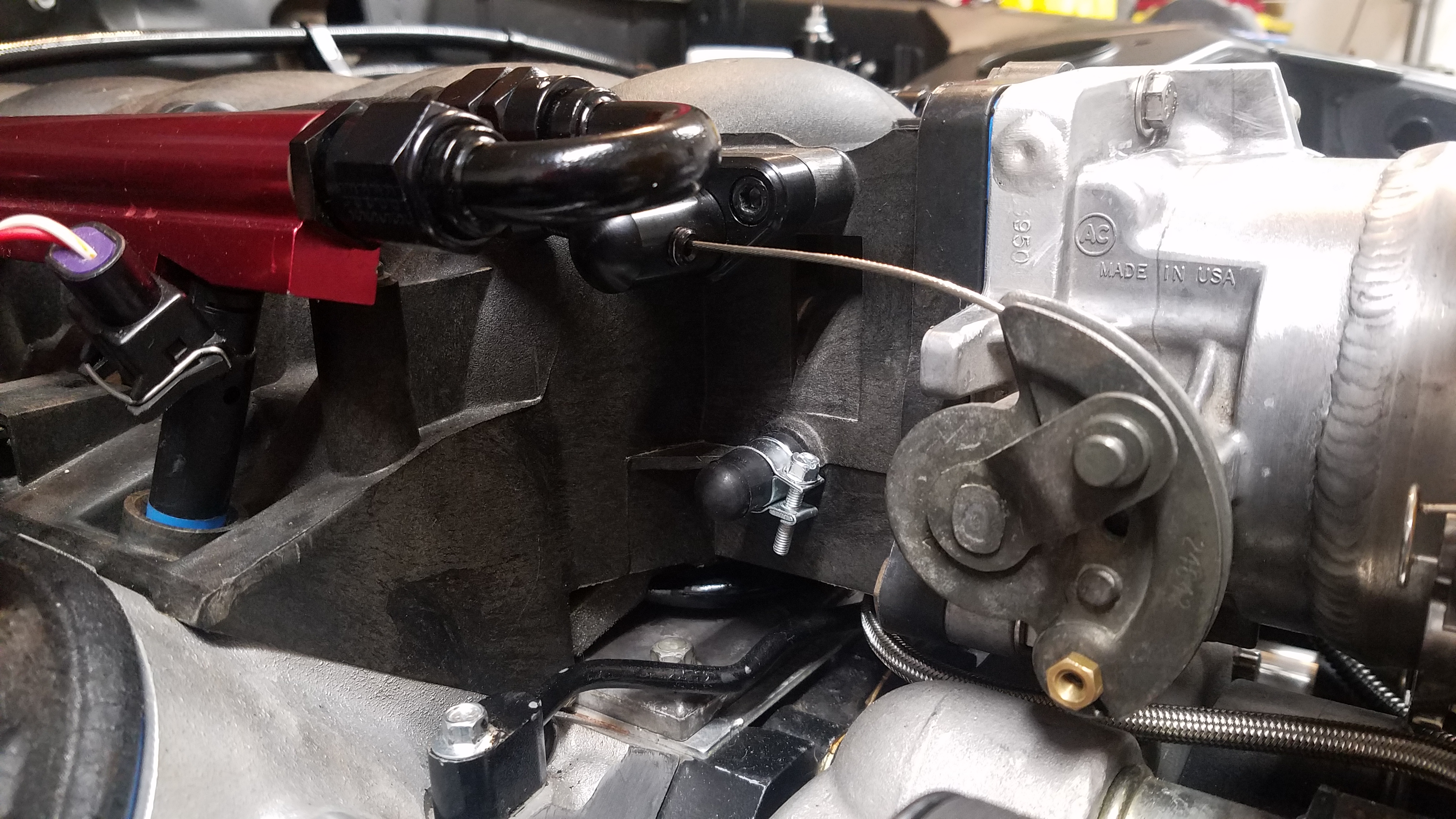
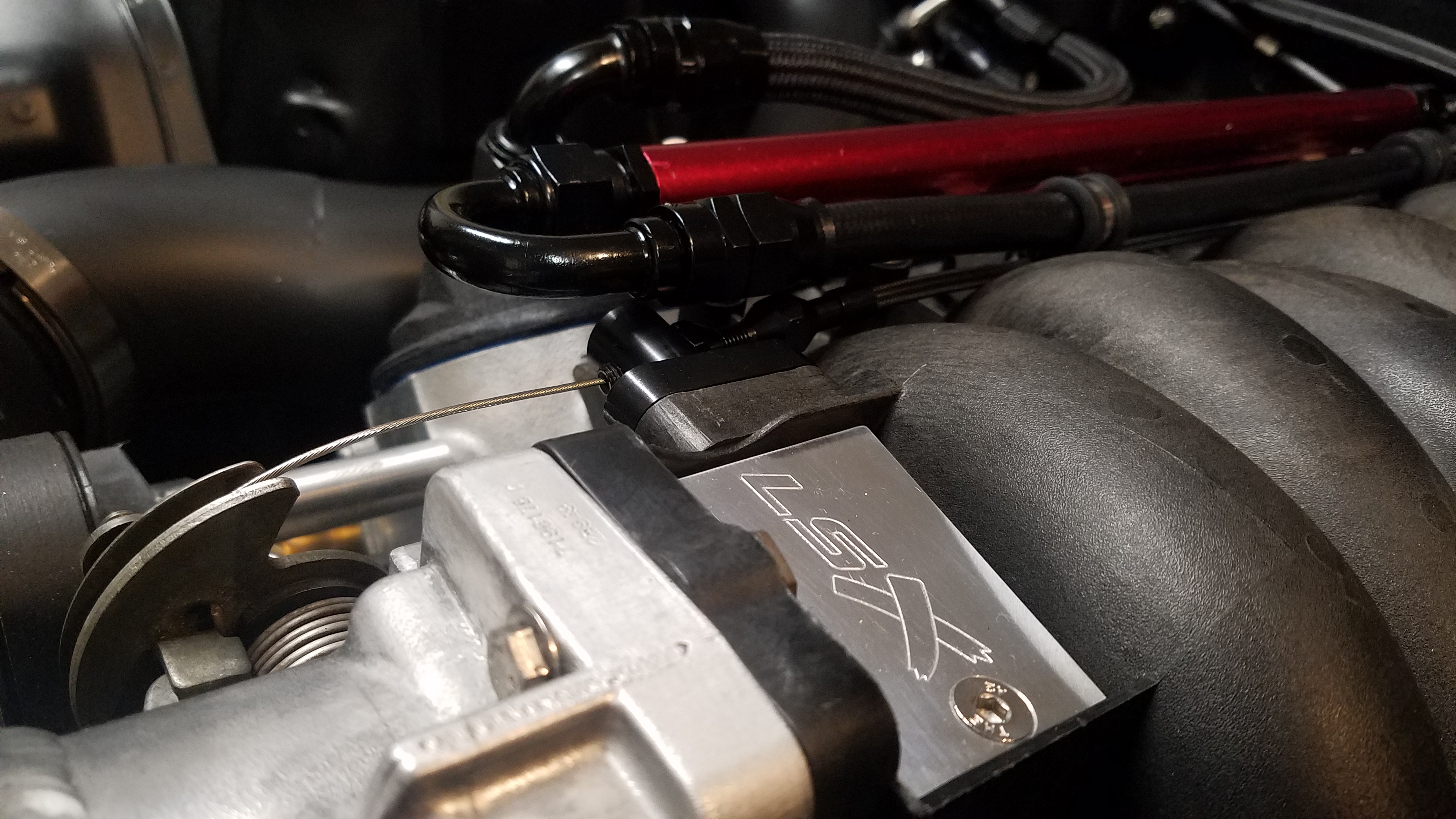
My lack of a throttle cable was needing to be addressed. Needless to say the damaged 33 year old throttle cable wasn't going to cut it. The Lokar Midnight series throttle cable was exactly looking I was going for. The Lokar cable used was part# XTC-1000LS148. Unfortunately this meant the gas pedal must be modified to accommodate the Lokar cable. My pedal solution was "combining" a S130 (280zx) & Z31 (300zx) gas pedal. Only the very top part of the S130 gas pedal that was used. I cut the last couple inches off & drilled the rivet ball from the end. Which left a hole perfect for Lokar clevis pin fit inside of. The only issue was clevis couldn't pivot freely. That was easily corrected with some filing. The top portion of Z31 pedal removed. It was made exactly the same length as the piece from the S130 pedal. Then the two were welded together to retain the factory length. Once this was done & installed I only had left was shortening the throttle cable. Here's some pics.
-
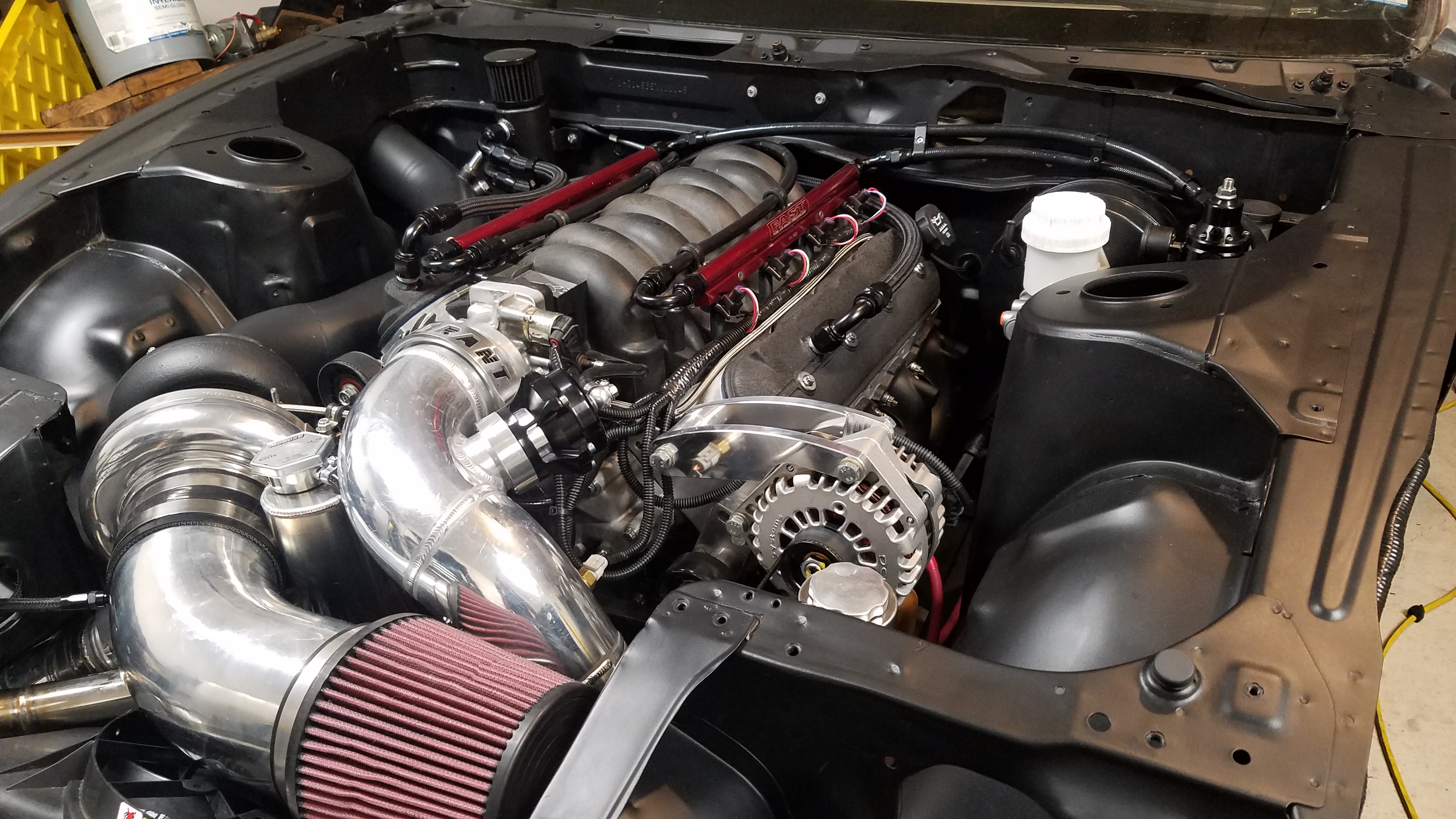
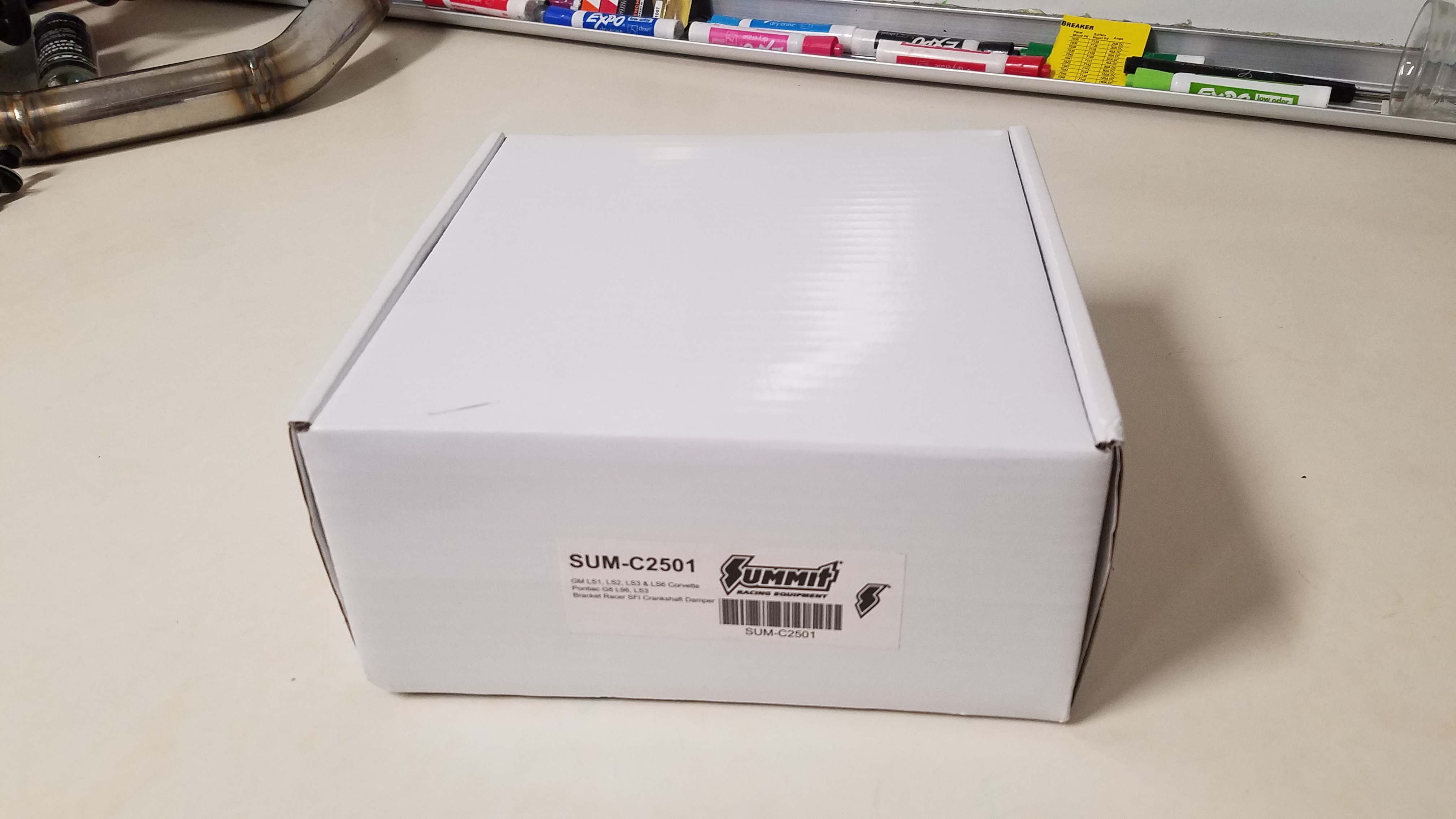
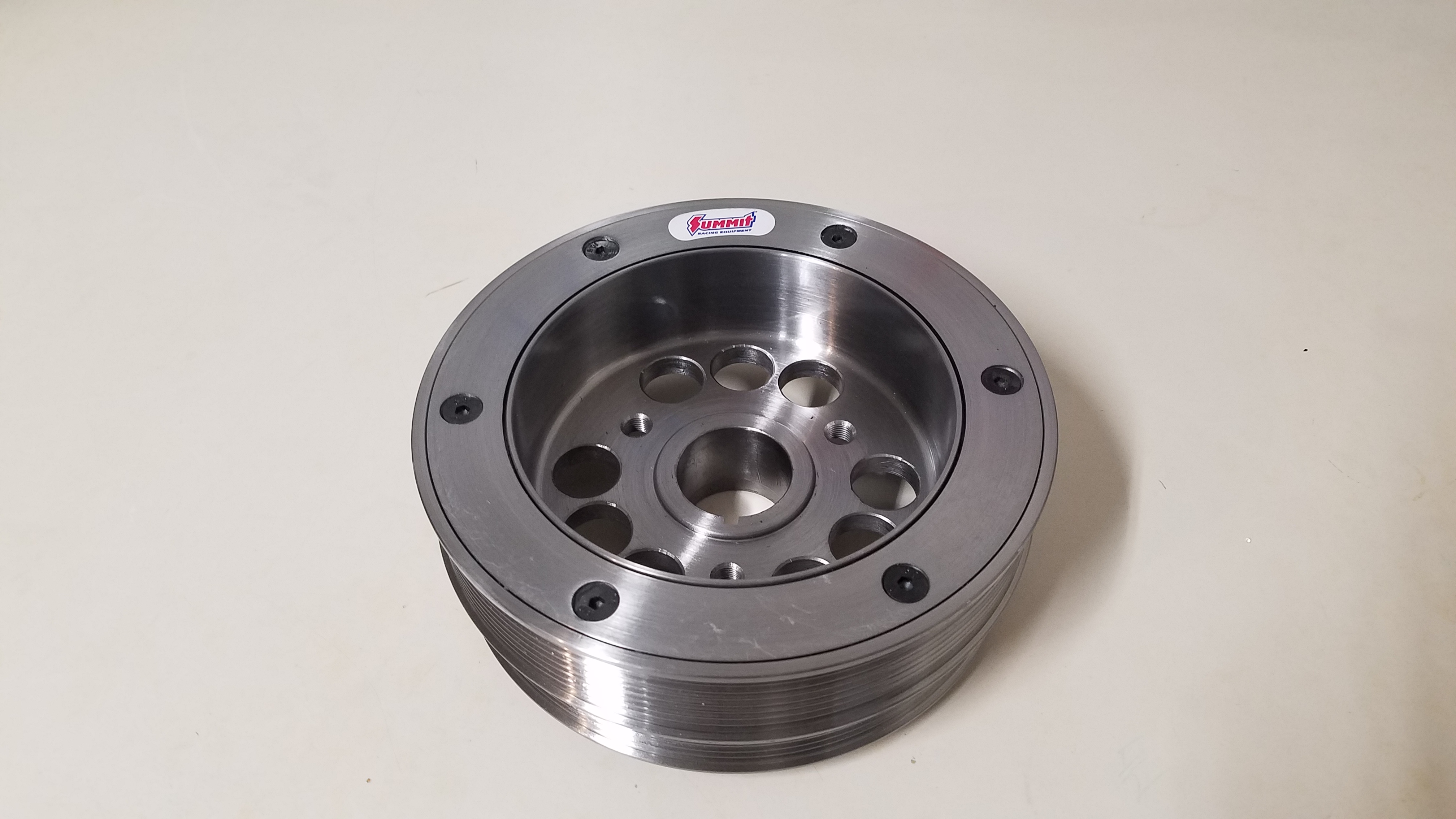
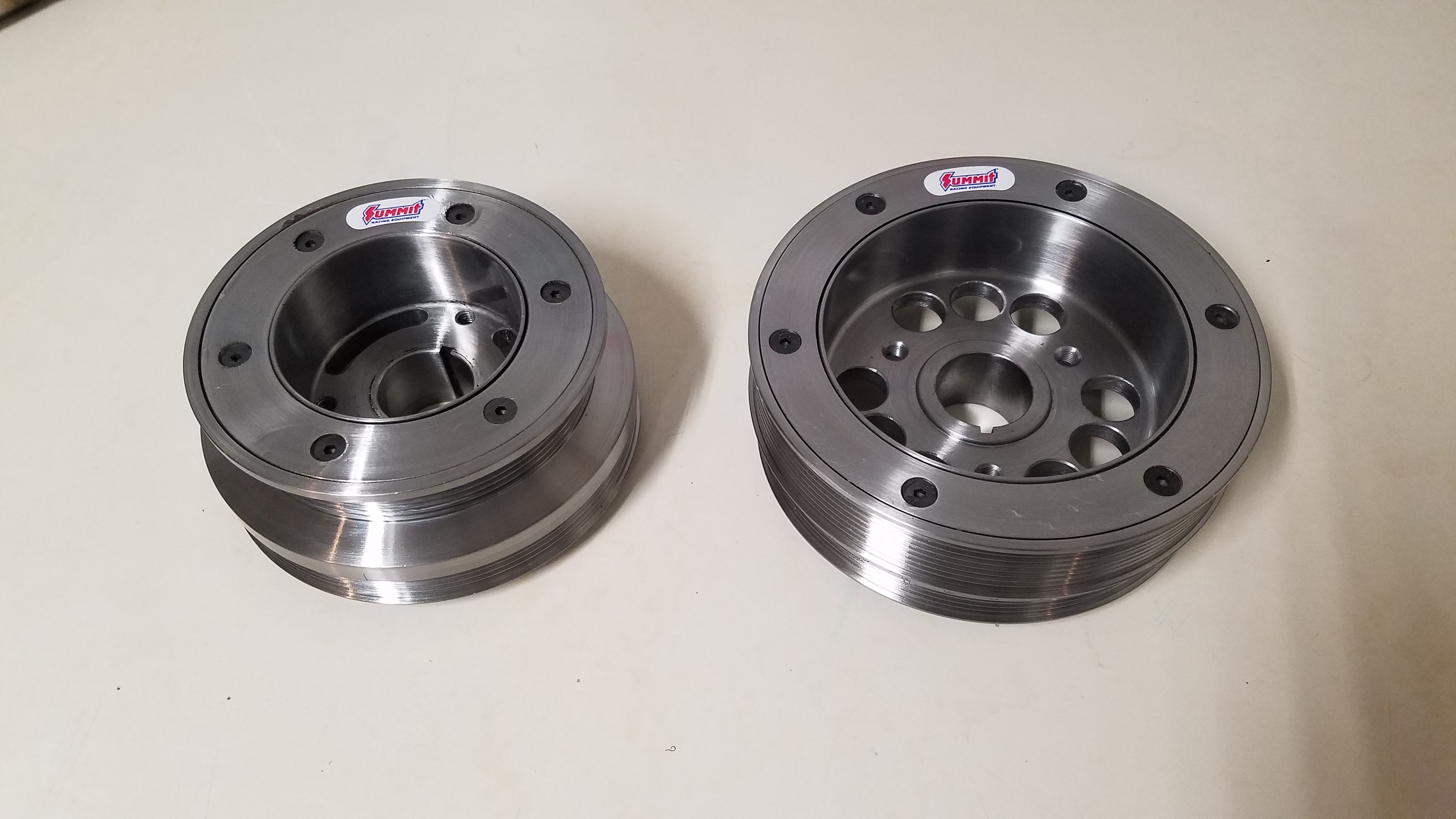
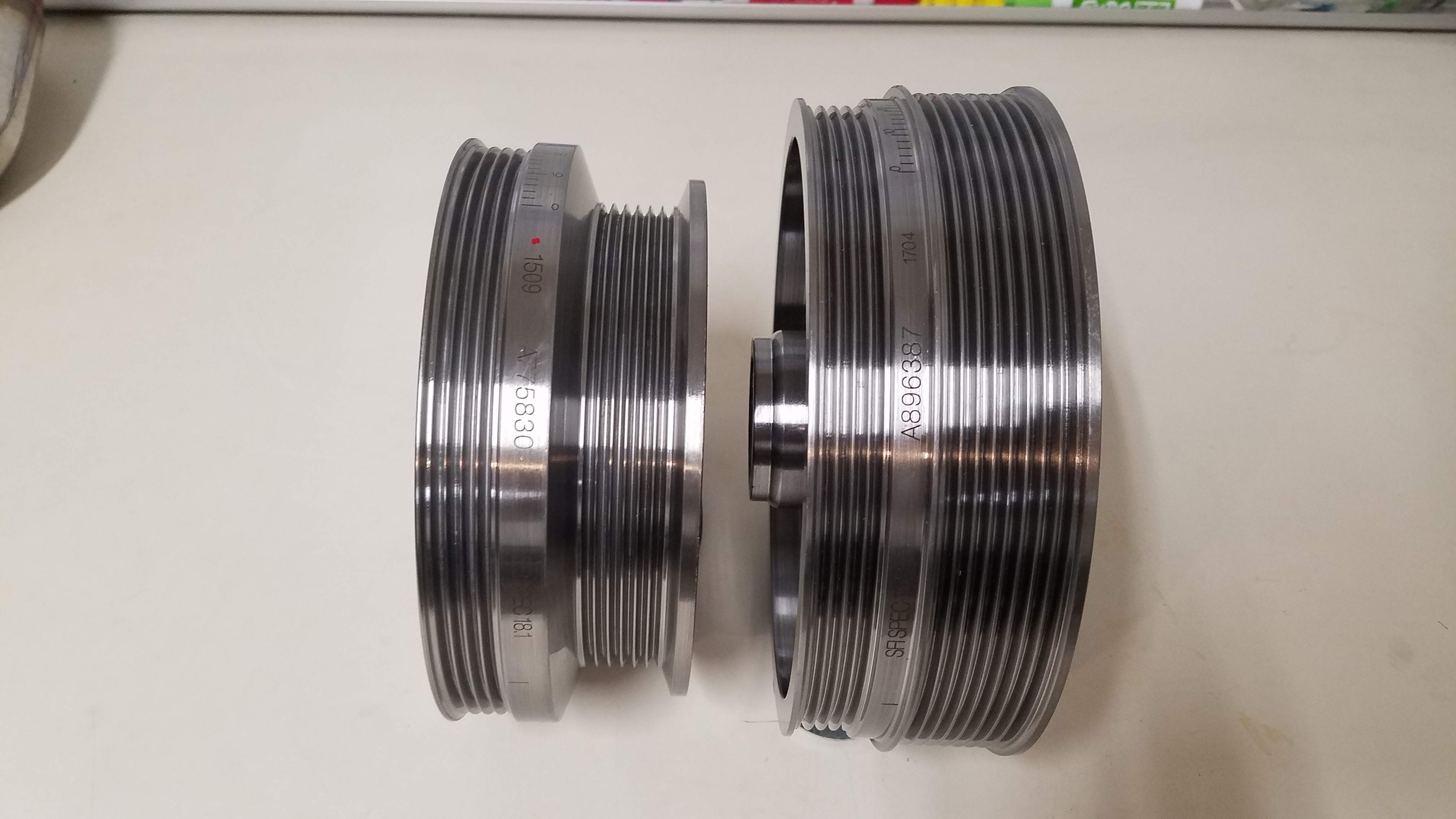
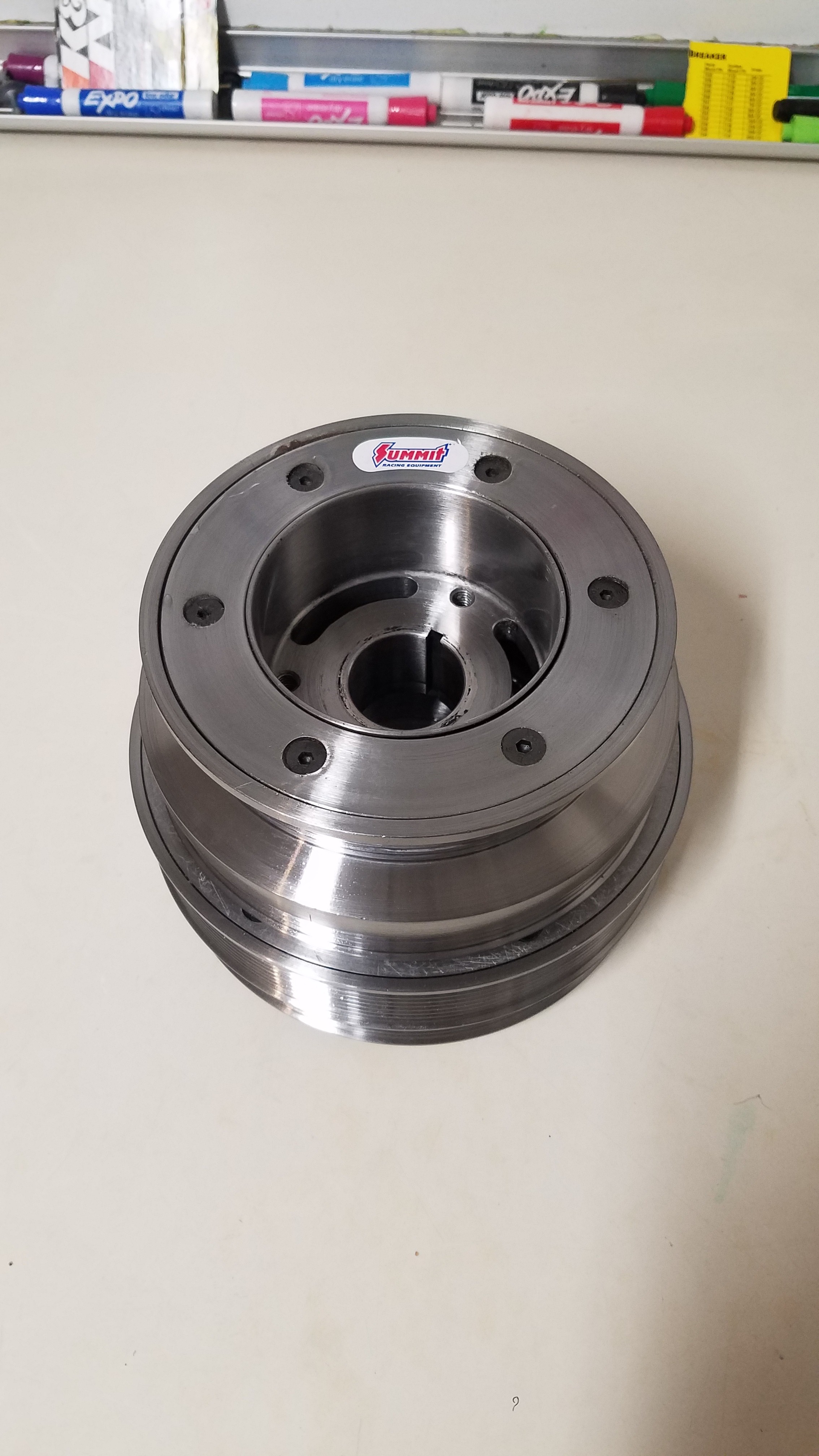
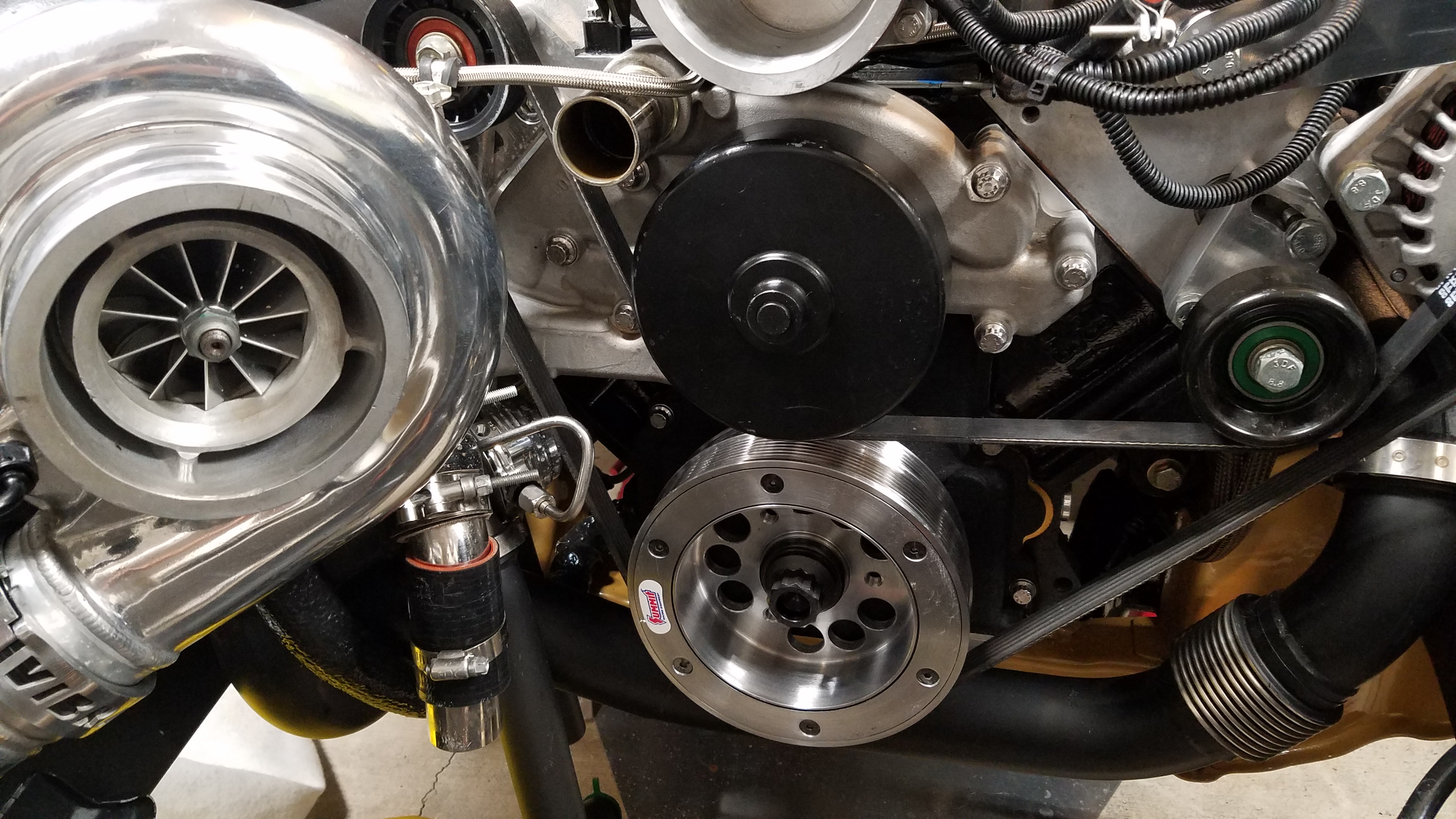
Many other's were also reporting they couldn't access/download their photos in bulk. Luckily I already have EVERY pic I've posted saved on my computer. With that said, I began exploring my options. I noticed most the free/extremely low cost options don't really allow you to use it on the "entire" forum. If you read the fine print in the terms it'll disclose "Not to be used for any sales and/or promotions. Nor should ____ be used on any website that has such a section." Or "You may not exceed X number of photos per page." Among other things. I wanted a image hosting solution that couldn't potentially to put me back to square one in the near future. Even if it meant spending a few $'s a month. The best bang for buck solution IMO was Smug Mug. I've got to admit, it's amazing! I don't know why the hell I had stuck with photobucket all these years. I've uploaded all the previously posted content on my Smug Mug. The content can be found here. https://turbolsxz31.smugmug.com/ They're under "Previously posted build pics". Each # folder contains the equivalent major group of post/ update. I.E. "Previously posted build pics 1" is the entire pic collection from my very 1st group of posts in this build thread. If there's anything you don't see here, but would like to see please let me know. Next for this update was replacing my underdrive harmonic balancer with a regular sized harmonic balancer. Originally Summit had regular sized balancer out of stock due to changing it's manufacturer. Which lead me to purchase an underdrive balancer. My old balancer was the Summit 25% underdrive part # SUM-C2503. The new regular sized balancer is part# SUM-C2501. The reason behind the change was I wanted more rpm for accessories. Mainly it was done for peace of mind. Below you'll see a few comparison photos along with it installed. I also included a video showing how the was held crank while I torqued the balancer bolt. https://youtu.be/CYNK7O_Fqdw
-
Well it's update time once again. I had originally planned to have this out by Christmas time, but things obviously didn't go as planned. I'm sure that you've noticed by now Photobucket has stalled/killed a good bit of forum content. I began to see an increase in pm's & emails regarding my content. Upon further investigation I encountered this dreaded image.
-
Thank you!
-
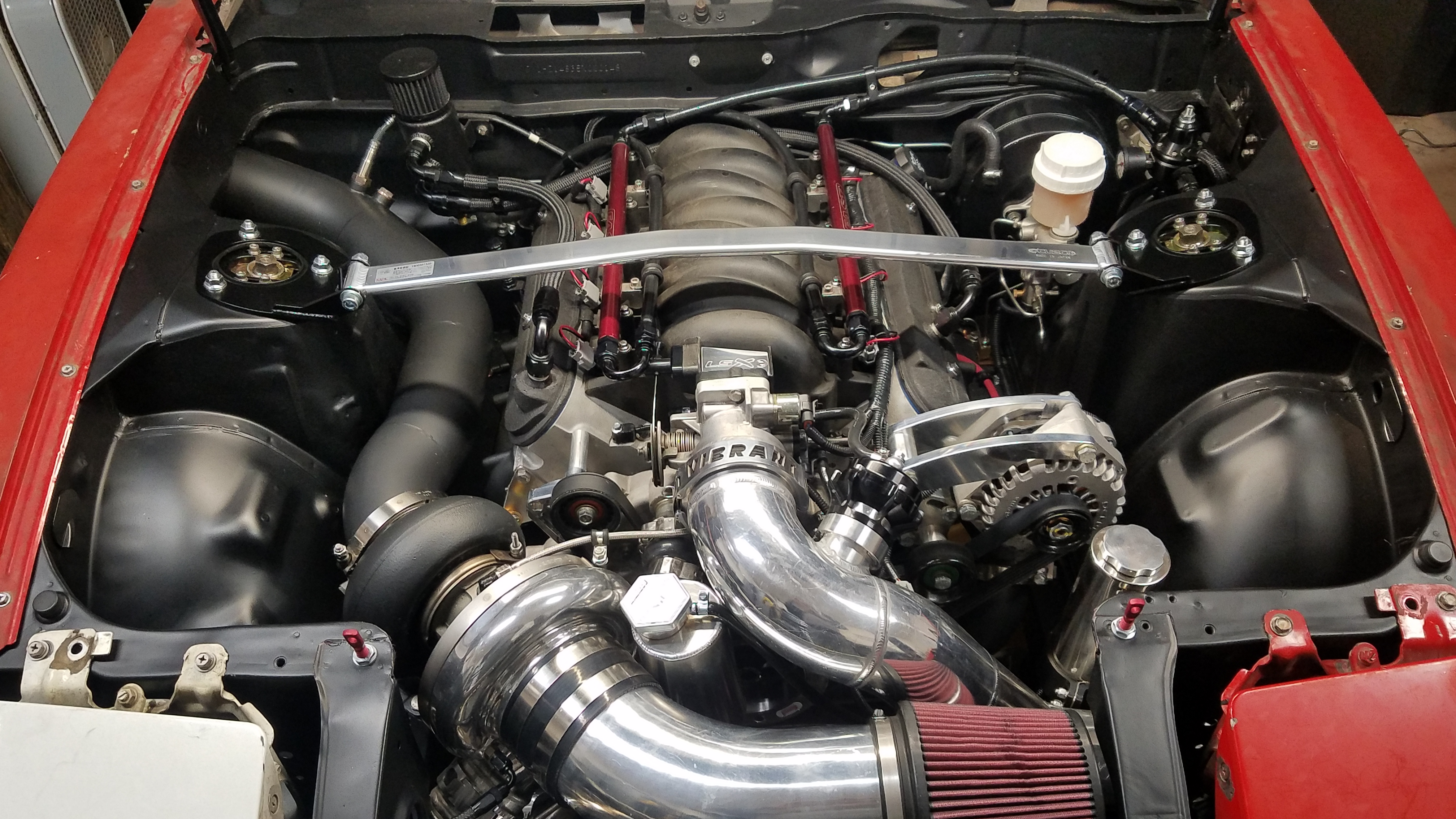
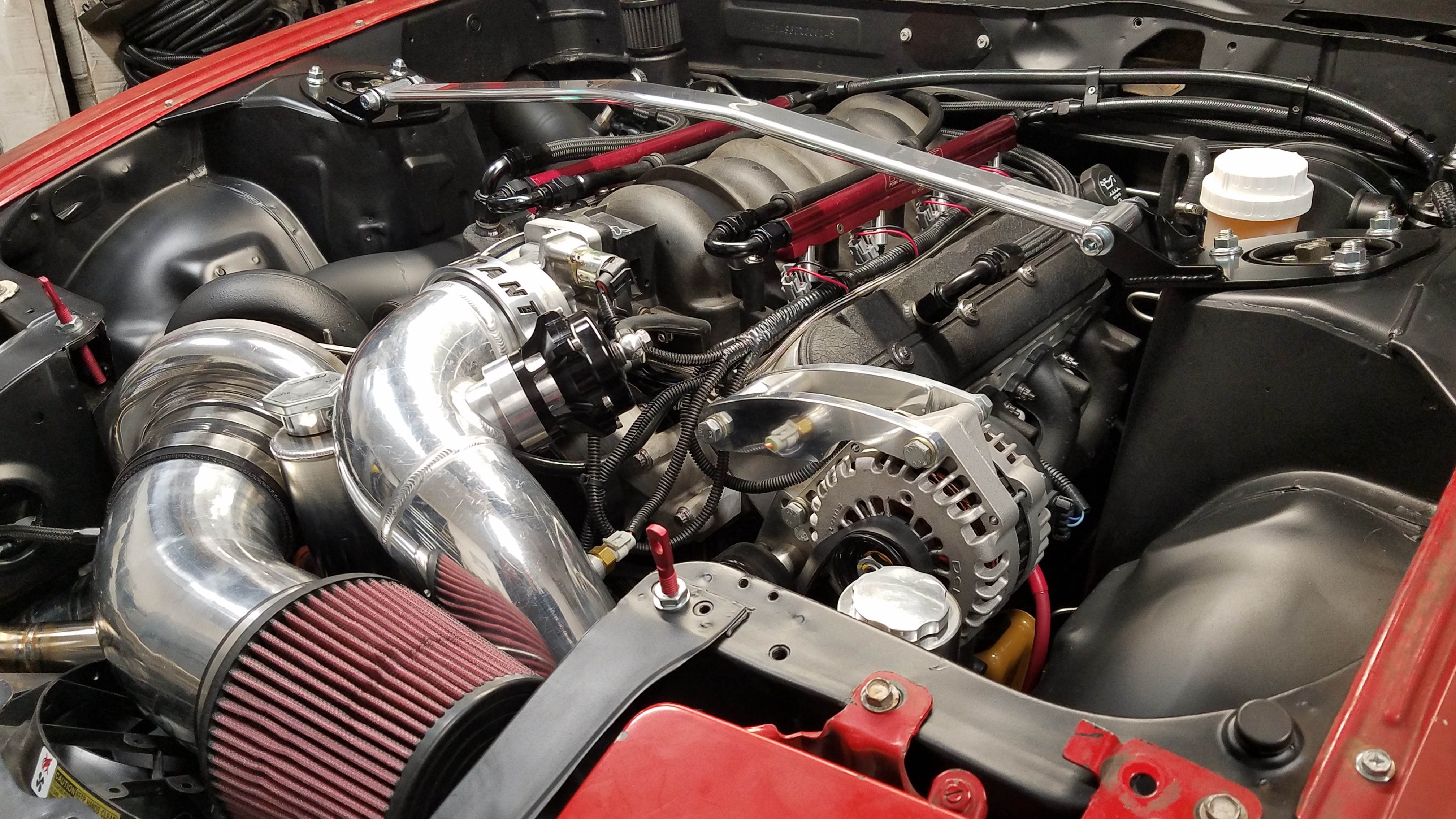
At this moment I was SO SO close to my very 1st start up I could taste it. Got some E85. Topped off my oil & coolant. Double & triple checked everything. Installed Tunerstuido on my girlfriends laptop(mine all shit the bed). Armed with my chicks laptop I started my 1st Tunerstudio project ever. Then loaded a Efisource pump gas base tune. Only thing I wanted to have setup before cranking was the oil pressure gauge. Well I along with my buddies Matt & Andrew fought with the IMEI process. With no luck I bought the registration. Finally I was ready to start the car. Cranked it several time. Had Not RPM Synced alert. Took several composite logs. Still couldn't figure out what was wrong. The tooth count was correct as was the tune. This was late Friday night. Emailed the logs to Efisoruce. Well I fought with it all weekend checking everything from wiring to sensors. Monday came around. I contacted Efisource. Initially they thought I installed the Cam 180 degrees out which I thought would be impossible. So I tore the entire car down to verify. Just like I thought it was perfect. Well they asked for my to degree the cam 180 out & take another log. (Which I did without the pushrods & rockers installed. Not wanting any crunchy stuff going on.) It gave me the exact same result. My E85 tested perfect too. With that done I put everything back the correct way. with the exception of leaving my coils & injectors unplugged. Then we began to suspect my OEM crank sensor. Due to the fact my tooth wave looked nothing like other peoples composite logs. So I went to my nearest dealer to buy another Factory GM sensor. Came back home & installed it. Gave it another try. Still Not Rpm synced. WTF!!!!! Now I reloaded the tune even though I hadn't changed anything beside the engine size for required fuel. Gave it several more tries. No Luck. Took a break to eat dinner. Came back out cranked it 3 more times. Still nothing...... Towards the end of 4th time I noticed my Not RPM Synced alert went away. Then checked the composite log to see what the Not RPM Synced line looked like. It was SMOOTH!!!!! I was like **** it. Hooked up my coils & injectors. Set my phone up to potentially record my very 1st start or fire which ever comes 1st lol. My girlfriend was armed with the fire extinguisher just in case. Began to crank it up after a several seconds the car STARTED!!!!!!!!!!!!!!! It actually runs now! It was an uphill battle the past 72hrs have been hell & heaven at the same time. I have everything else to put it together & on the road but a custom driveshaft. I hope to take it to ZCON in Austin in June. It'll be very very close but I'll still try. Thanks too all that motivate, view, & follow my build!!!!! Biggest Thanks of all goes to my Girlfriend for putting up with this never ending car.(She honestly was more excited than was!) Enough talking here's some pics & videos! 1st Start Cutoff test
-
Next was ditching my outdated fusible links. They're a pain in the ass to locate. Really just in general. Maxi fuses were my meal ticket IMO. They Are held by a JL audio 4 gang power distribution block. I began to look for a easily assemble spot to mount it along with other fuse blocks/ terminals. Not finding anywhere, a "trap" door was constructed. It's 1/4in ABS plastic with a stainless steel hinge attaching it to the firewall inside the cabin above the passengers feet. Flush mount furniture "nuts" were used as anchors for everything to be bolted to the panel. That way passengers wouldn't scratch their feet on bolts & what not. The panel is held up level with the dash using custom brackets & threaded knobs. Turned out quite nicely for little $ I invested into it. The fuse box in the upper left is all 12v switched. The other fuse box/group with the fused relay is for the MS3 Gold Box. Maxi fuse box/block towards middle/bottom is what replaced my fusible links. Moving on I install the new AEM 30-0300 X-Series Wideband UEGO AFR Sensor Controller Gauge. (Note there is multiple versions some have OBD2 support unlike mine.) It has more wires than previous Uego units I've used. It also responds much faster too. I reached out to AEM looking for support but they just tried to sell me a Infinity & AEM net unit. They insisted it was the only way to enable communication for data logging. GTFO Ain't No body got time for that. I ended up brainstorming with Mike @ EfiSource about it. They said they hadn't heard of anyone using the X series Uego with MS3 Gold Box yet. I ended up only using the Red(12v switch), Black(Ground), White(Analog +), Brown(Analog -). I wired the White to the 02 wire & brown to Sensor ground on the MS3 Gold Box harness. Works like a champ. I also wired/set up the AEM Trim pot switch for boost control. Big Thanks to Matt Happel for all the info covering this! I also wired up the Factory GM 3 wire Oil psi sensor & Mac 4 port valve. According to MAC the 4 port valve it only requires a 12v switched on any of the 2 wires. (On the 12v switched side I installed a 10amp fuse. per their recommendation) The other goes to the ecu which sends a ground signal. In the past I've never any issues with the 3 port without a fuse but whatever lol. I made this speedo block off. By modifying broken speedo sensor & tapping it to approve a old magnetic LS oil drain plug. So I made this contraption/rig to prelube my engine. It was a old fresh water pump I tore down/cleaned. The ball valve "regulates" the amount of oil going into the engine. The blue 90 is where the oil goes. The pump is activated via my power probe 3. This setup yielded me 25psi of oil pressure before start up. (I pumped 3 qts in) This setup isn't pretty but it worked. It's only dumb if it doesn't work......... or that's what they say.
-
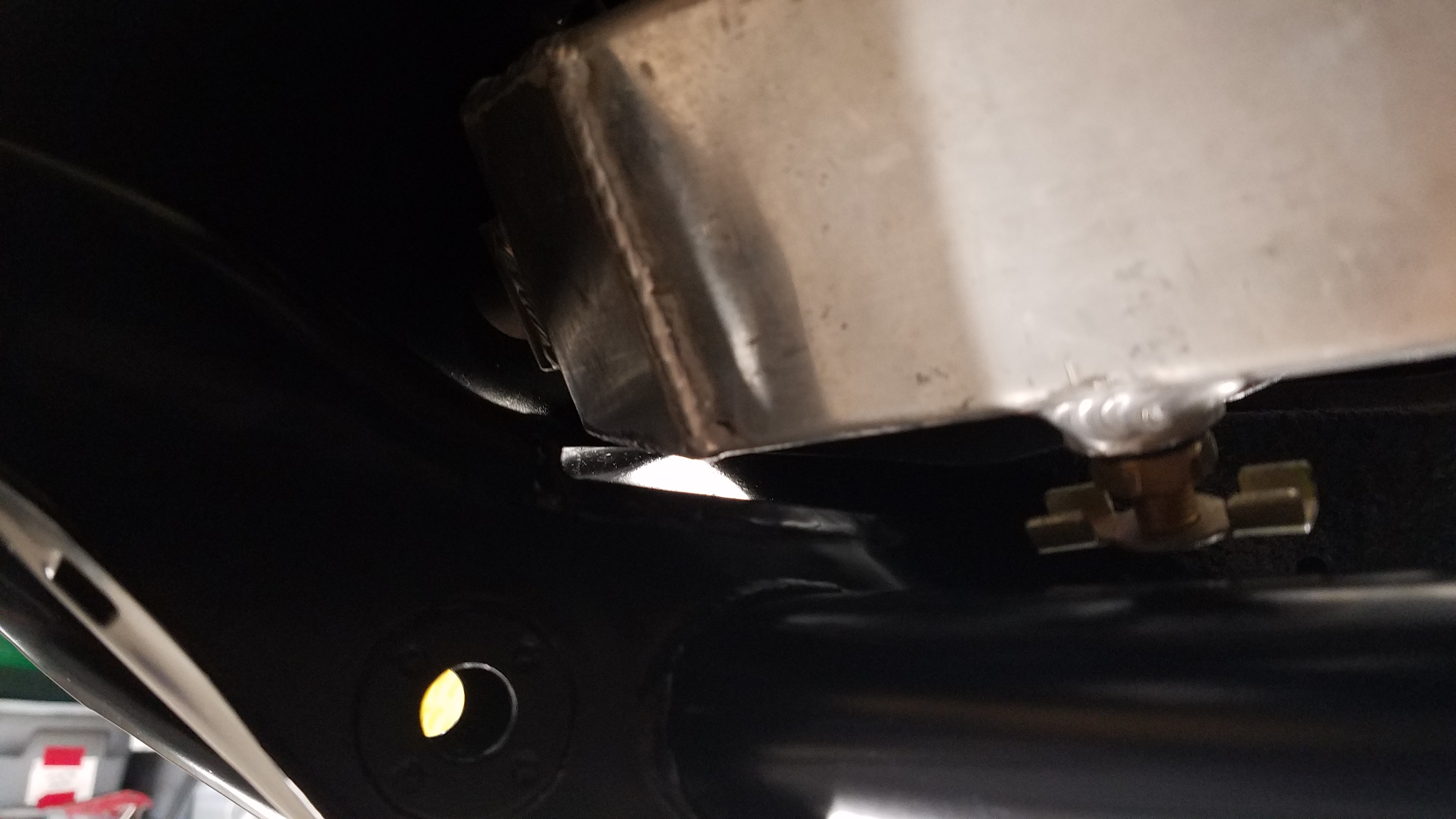
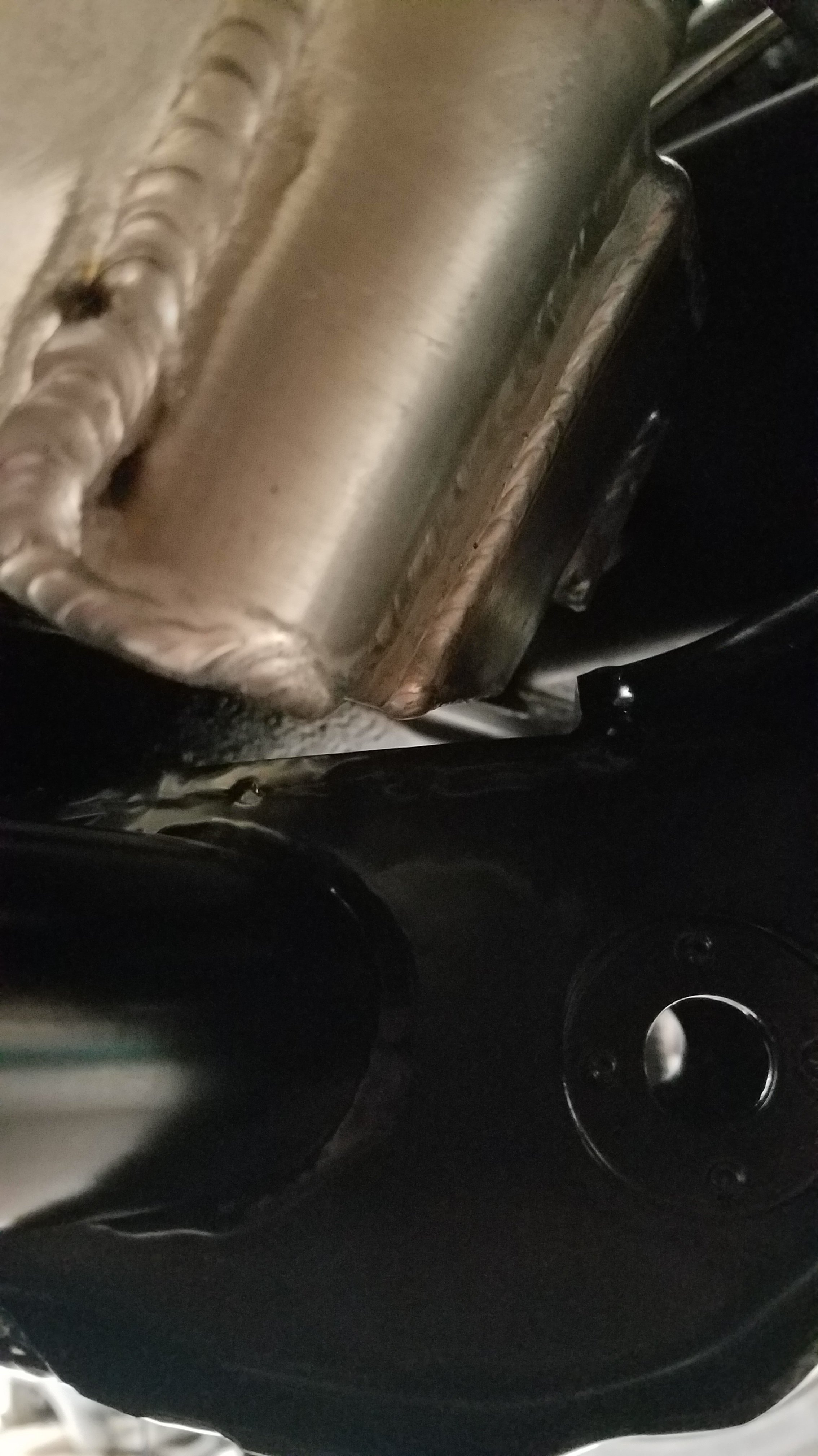
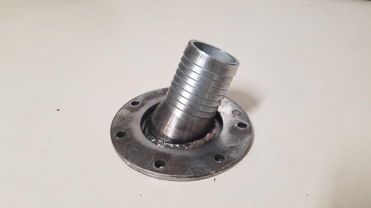
After I finished up the alternator/battery wiring I finally got my fuel tank back. It wasn't until I was installing it I had a Homer Simpson "DOH!" moment. The battery partially blocks the filler necks path. Here was my solution.


.jpg.77023aaeddf2c822810336d56cd5d571.jpg)