
dat240zg
-
Posts
817 -
Joined
-
Last visited
-
Days Won
1
Content Type
Profiles
Forums
Blogs
Events
Gallery
Downloads
Store
Posts posted by dat240zg
-
-

Saw those. Just didn't want to get into a bidding war with someone and end up paying out the wazoo for them.
Thanks.
Bryan
Dat240zg
-
Needing the pair. Thanks for your help. Please include shipping to 72758.
Have a great one!
-
Looking for a set of billet R230 CV adapters.
Bryan
Dat240zg
-
I've searched and can't find the answer, so I'm hoping someone else has already experienced this.
I'm getting ready to pull the trigger on a 2010 Infiniti G37 R-230 rear end. Any one know a reason why the newer R-230's won't work in the swap (different bolt patterns, spacing, mounting, etc)?
Bryan
Dat240zg
-
Finally in a position to get the R230 swap going, so...
I'm hoping to find someone who may be abandoning an R230 swap. I'm needing the entire mounting kit, diff, axles, etc.
Anyone have wanting to get rid of theirs?
Bryan
Dat240zg
-
"Is this for the MAF of speed density systems?"
I may be wrong, but I think he meant to type MAF or Speed density.
-
Let me know if I can help you with info.
Bryan
-
-
Well, this started several months ago when the Z started cutting out intermitantly and got to the point where it was undrivable. I started digging in to the wiring harness (potential for disaster: high) and found a whole nest full of screwups by the supposed "pro" that I initially paid to get the car going. Wires that were twisted/taped together for a connection, some butt connectors and a few soldered joints. And to add to that, there was extra wire out the wazoo.
Wheelman encouraged me to dive in to it (go ahead jump!!!) so I got to pulling the entire harness from the car. BTW, I have no wiring experience beyond installing my own sound systems, so this was a big step.
I figured that I could share the info that I gathered. If you're going to tackle this, you'll need (at least) the following websites: http://shbox.com/1/harness.htm and http://www.thirdgen.org/techboard/ltx-lsx/176800-lt1-wiring-dummies.html.
I also decided that I needed to learn to solder well instead of just using butt connectors, researched that, bought a good solder gun and practiced on some scrap wire that I had. One cool/simple/cheap thing that I came up with was a way to build a rig to do my soldering in. I bought a set of aligator clips at Wal-Mart, cut the wires and inserted them, clip up, in my vice about 3 inches apart. Tightened the vice and, voila, a perfet way to hold my wires secure while I soldered them. Total cost: $1.38.
I started by removing the harness and began tagging each wire and connector (I just used small pieces of masking tape to label each wire). Take your time on this and make sure that you're clearly labeling each one. Better to label well than to try to remember later. If you're just going to repair your harness, I wouldn't de-pin the ECU connectors. I wanted the harness to fit like it belonged in the Z, so I went ahead and labeled each wire at the ecu end (what it went to and which pin it went to - really important!!). To depin the ECU connector, open the clam shell covers on the back of the connector and then remove the colored cap on the front side (just takes a small flathead screwdriver and a gentle touch). Then, to depin the connector, lift the white retaining plastic piece with the flat head and gently push the pin out the back side of the connector. Again - don't do this unless you've really labled the pin number for each wire!
Next step is to seperate all of the wires as much as possible. The LT1 harness (maybe others too?) is weird in that it uses common power and ground wires throughout - and the placement of these clumps of common power and ground wires doesn't make much sense. Make certain that you mark each wire where it enters each common power and each common ground. After seperating all of the wires, I found that it really boiled down to needing a common power on both the driver and passenger sides as well as one up nearer to the ECU. Same thing with the common grounds.
After taking time to really get to know the harness and where things belong, I started by taking one connector at a time, plugging it in and measuring the amount of extra that I had at the ECU end. Then, depending on if the wire had been poorly connected or damaged, I either fixed the problems or shortened the wire as needed.
To save your self a lot of frustration and time, make sure that you have all of your supplies before you start: Solder gun, solder, plenty of differnt sizes of wire heat shrink, a small torch (for the heat shrink), a good pair of wire strippers, wire cutters, scissors, electrical tape, masking tape and a fine point sharpee (for labeling wires).
The old adage of measure twice, cut once really applies here. You don't want to get your wires too short (where you have to stretch them to fit - not bueno). Once you do cut the wire, make sure that you slide a piece of heat shrink to cover the solder or butt connector before you connect them back. Don't ask me how many times I forgot to do this.
Plan on taking the harness in and out 3 or 4 times before you finish. Also, if you're a beginner like me, plan on the job taking a solid 4 days. Once you've repaired/trimmed the wires, begin building up the harness on the Z. Especially on the LT1, make certain that your grounds are done well. Also, as you're going through the harness, look for damaged connections - I found one on the optispark connector that was damaged and needed repair.
When all your wires are done and triple checked, plug everything back in but don't wrap it back up. Test it first. I was fortunate that it started first time. Which was then quickly followed by me running around in the front yard yelling like a crazy man. The neighbors are used to it now.
After that, I re-wrapped the harness all pretty and called it finished! One nice side benefit of this job was that I'm not nearly as freaked out by wiring - rather, the harness makes sense now and I believe that I'll be able to diagnose things better as a result of knowing it better.Here is the wire listing for the LT1 that I used from the thirdgen website (I didn't come up with it - they have a resident LT1 expert):
A is RED PCM connector.
B is BLACK PCM connector.
C is GREY/CLEAR PCM connector.
D is BLUE PCM connector.
Pinout Color Where it goes:
A2 blk/wht PCM Ground
A3 blk Injector #1 Control
A4 lt blu/blk Injector #4 Control
A5 yel/blk Injector #6 Control
A6 red/blk Injector #7 Control
A7 dk grn/wht Fuel Pump Relay Control
A9 gry EGR Vacuum Control Signal Solenoid Valve Ctrl
A10 dk blu Secondary Cooling Fan Relay Control
A11 dk grn Cooling Fan Relay Control
A12 tan/blk Electronic Brake & Traction Control Module
A13 wht TACH Output
A14 brn Air Pump Relay Control
A15 dk blu Performance Mode Indicator Lamp Control
A18 tan/wht PCM Ground
A19 lt grn/blk Injector #2 Control
A20 blk/wht Injector #5 Control
A21 pnk/blk Injector #3 Control
A22 dk blu/wht Injector #8 Control
A23 orn/blk Electronic Brake & Traction Control Module
A25 dk blu Fuel Enable Signal(Theft Detterant System)
A31 ppl VSS Ground
A32 yel VSS Signal
B1 dk grn/wht A/C Request Signal
B2 red/blk Low Resolution Signal
B3 pnk/blk Distributor Reference Low Signal
B5 wht Ignition Control
B6 blk A/C Evaporative Temperature Sensor
B6 blk A/C Refrigerant Pressure Sensor
B6 blk TPS Ground
B6 blk Trans Fluid Temperature Sensor
B7 lt grn 1-2 Shift Solenoid Control
B8 dk grn/wht VSS Output
B12 yel/blk 2-3 Shift Solenoid Control
B13 gry Skip Shift Solenoid Control
B13 wht Control Solenoid
B14 red Distributor Ignition Feed
B15 orn PCM Battery
B16 blk MAP Ground
B19 yel MAF Sensor Signal
B20 ppl/wht OR lt blu/blk High Resolution Signal
B21 dk grn A/C Clutch Status
B28 gry 5v TPS Reference
B28 gry A/C Refrigerant Pressure Sensor
B29 gry MAP 5v Reference
B30 pnk PCM Ignition Feed
B31 orn PCM Battery
C1 lt blu/wht IAC Coil
C2 lt blu/blk IAC Coil
C5 lt grn/blk IAC Coil
C6 lt grn/wht IAC Coil
C7 tan rt o2 Sensor h02s LOW
C8 ppl rt o2 Sensor ho2s HIGH
C11 lt blu Electronic Brake & Traction Control Module
C13 lt blu Performance Mode Switch Signal
C14 lt blu/blk Brake Signal
C15 orn/blk Park Nuetral Position Sensor(4L60E ONLY)
C16 red/blk Pressure Control Solenoid
C19 tan/wht lt o2 Sensor ho2s LOW
C20 ppl/wht lt o2 Sensor ho2s HIGH
C21 tan IAT Sensor Signal
C22 dk blu TPS Sensor Signal
C23 lt grn Map Sensor Signal
C25 yel ECT Sensor Signal
C28 pnk Trans Fluid Temperature Sensor
C29 dk blu Trans Fluid Temperature Sensor
C30 red Trans Fluid Temperature Sensor
C32 blk/wht PCM Ground
D1 tan/wht PCM Ground
D2 lt blu/wht Pressure Control Solenoid
D6 brn Torque Convertor Clutch Solenoid
D6 lt grn Reverse Inhibit Solenoid Control
D8 dk grn/wht A/C Clutch Relay Control
D9 brn/wht Malfunction Indicator Lamp
D10 dk grn/wht EVAP Canister Purge Solenoid Valve Control
D11 tan/blk Torque Convertor Clutch Solenoid
D12 red A/C Refrigerant Pressure Signal
D12 red/blk A/C Refrigerant Pressure Sensor
D15 wht Skip Shift Lamp Control(T56/T5 ONLY)
D20 wht/blk Output Field Service Enable.
D22 dk blu Knock Sensor Signal
D24 dk blu A/C Evaporative Temperature Sensor
D24 dk blu A/C Evaporative Temperature Sensor Signal
D28 yel/blk Trans Fluid Temperature Sensor
D30 pnk PCM Ignition Feed
D30 tan Serial Data
Hope this may help someone else get brave/crazy. Have a great one!
Bryan
Dat240zg
-
Paul:
Money sent to you for the cover.
Thanks,
Bryan
Dat240zg
-
I'm interested. Any pics?
I think that I have the upper and lower piece. If you are still looking send me a PM and I will try to locate it.
-
I'm looking for a nice to very nice condition (no cracks, broken mounting tabs, etc) steering column cover for a 280Z. I'd like to pay around $35 for it. Please let me know if you have one you'd part with.
Thanks in advance,
Bryan
dat240zg
-
I believe that I have a new set of the motor mounts from a older version of my swap. Just the mounts themselves though. If you're interested, I'll let them go cheap. $25 + $5 shipping.
Bryan
-
This is probably a really stupid question, but here I go. In trying to track down a injector wiring problem, I'm going through my harness and seeing lots of excess wire length (it's just doubled back on itself in the harness). Is there any reason to not go through and shorten the wires down to the length that works best for the Z? Will shortening the wires by removing the extra length and then connecting them back together weaken the electrical signal?
I'd like to neaten up the harness, but don't want to get myself in a worse position than I already am.
Thanks in advance for your thoughts.
Bryan
Dat240zg
240Z (#248) w/LT1 & T56
-
Don't rub it in John. I just got the Stealth unburied...
Had a blast being the only sports car on the road! The neighbors just shake their heads now...
Bryan
-
This is the second big snow in as many weeks. Sure is nice to have all wheel drive on the stealth! 4 wheel snow drifting ought to be an Olympic sport...
-
I recognize that for those of you that live in the great snowy north, this won't amount to much. But for Arkansas, this is a record...
We ended up getting about 22" in 6 hours, sure is beautiful!
Buried Stealth
Torture!
-
I'm looking to buy a wreck through Copart but really think that it's crazy to pay $450 to a regular broker just to bid on a $500 car. If anyone knows someone or has a bidder number I'd be more than willing to pay a (smaller) fee for the use of your number.
Thanks in advance,
Bryan
Dat240zg
-
Thanks for the offer, but with the setup I had, I was stuck size wise with a 180. All worked out in the end.
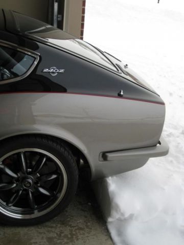
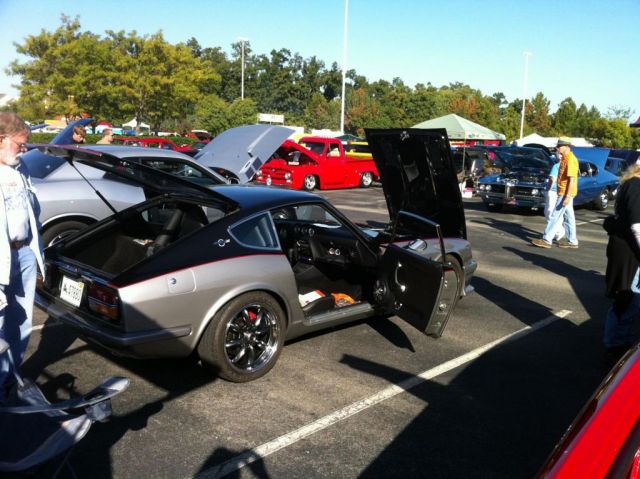
Here are a few pics:
There were a few really nice cars there - I was wishing that I could get away to see more of them. One was a old school Challenger convert that had a complete viper drivetrain swap (cool), but for the over the top element, had teh entire viper interior, front and rear suspension. Very cool!
What did amaze me was the number of non-bikers that would come up and tell me their Z stories - neat to see how many people really get nostalgic about 'em. Now to get working on the R230 swap...
Bryan
-
Won Best in Class...woot woot!!
What a day that was.
Short summary:
Friday - Take the day off of work to detail car out; check all of the fluids, and when I pull the drain plug on the diff (R190 LSD), I see some shavings on the magnet. Stick my finger in side and find 6 or 7 pieces of gears the size of my thumbnail!!!!
Friday PM - call Sommers up begging for any diff that I can swap in to get to the show, he drops what he's doing and we search through his hoard of parts, no dice.
Friday PM, #2 - call Jim Daniels, aka Zup on classiczcars and go through the same situation, but this time get lucky, as Jim gives me the rear end from the Z he's restoring.
Friday PM, #3 - 3pm - spend the next two hours swapping diffs, scraping up my MML control arms (!@#@$@$!W$#@)and test the car by 5pm. Head to the football game at the High School where I work, come home and detail til past midnight.
Saturday - Head down to Bikes, Blues and Hot Rods too, enter late, and spend the next several hours trying to convince a bunch of inebriated bikers that this isn't a furrin piece of crap....
Note to those who are interested: Getting irritated and telling said inebriated bikers that my Z is more American than their Harley is not the best idea.
Winning Best of Class was sweet! Big thanks to David and Jim.
-
Just checking...I'll have #248 entered again this year. They've created two new import categories (think that it's before '80 and after '80) so it should help. Last year they had me in the same category as the $100K+ trailer queens...it was ridiculous.
Let's get some Z's there!!! If you're going to go, let me know - it'd be cool to park them all together.
Bryan
-
I'm looking at purchasing a '92 Laser RS (DSM) and - being 15 hours away - was wondering if there was someone who could go and give it the old "turn your head and cough" checkup.
If so, please let me know! Thanks in advance.
Bryan
Dat240zg
-
The last thing on my list of things to do to finish #248 is to complete the Honda wiper motor swap. Does anyone have a list of what wires on the Honda wiper motor do what? For example, high speed = ? color, Low speed = ? color, Intermittent = ? color. I'm in a different spot as I have redone the whole wiring system. Thanks in advance for the help.
BTW, I have searched and found a diagram but it didn't have the info that I was needing.
Bryan
-
Well, this is getting a little crazy. Last year I sheared a driveshaft at the rear of the car, directly in front of where the shop had spliced the Datsun and Chevy pieces together. I got a little laugh out of it and chocked it up to ton's o' tourqe and a weak DS. Well, it looks like the problem is repeating itself. Which brings me to my question...
I know that this will sound like a dumb question, but if the motor/tranny and the rear end were out of alignment, would that result in the DS going out like this? The car only has 120 miles on it. Since the first time I started it after the LT1 install, I've had a rhythmic vibration that we initially thought was due to two piece wheel adapters, etc. We switched wheels and did away with the adapters, but no luck. Vibration still remains and I'm wondering if it's a symptom of the problem. The rear end is a very aggressive R-180 LSD.
I know that many of you have much more experience than me, so I'm hoping that someone may shed a little light on my problem
Thanks....
Bryan
 After that, I re-wrapped the harness all pretty and called it finished! One nice side benefit of this job was that I'm not nearly as freaked out by wiring - rather, the harness makes sense now and I believe that I'll be able to diagnose things better as a result of knowing it better.
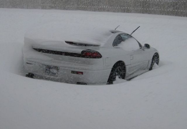

WTB: JDM 240z tail lights
in Parts Wanted
Posted
How much are you looking to spend? I have a set that are on my 240.