Sam280Z
-
Posts
395 -
Joined
-
Last visited
-
Days Won
4
Content Type
Profiles
Forums
Blogs
Events
Gallery
Downloads
Store
Everything posted by Sam280Z
-
Which lead are you concerned about? Pin 2 on the MS DB37 connector is a ground. You should run the CAS signal to pin 24. If you have a pre-assembled V3.57 board, you can install the 1K Ohm pullup resistor internally on R57. It keeps the wiring cleaner. You should use shielded wire with the shield grounded at the MS. The other CAS signal wire can be left alone / disconnected. The difference in the two pics you posted is that the megamanual install is getting the tach signal from the coil neg. The DIY install is getting the CAS from the 280ZXT optical pickup and then driving the coil. Sam
-
MS3 w/ MS3X Install - L6 turbo, sequential injection & boost control
Sam280Z replied to Sam280Z's topic in MegaSquirt
And now I have a MAP sensor problem. http://www.msextra.com/forums/viewtopic.php?f=131&t=43918 -
MS3 w/ MS3X Install - L6 turbo, sequential injection & boost control
Sam280Z replied to Sam280Z's topic in MegaSquirt
Well I'll have to mess with it some more. Random sync loss came back on Sunday. Not as frequent, but very annoying. I had not changed anything at all. -
MS3 w/ MS3X Install - L6 turbo, sequential injection & boost control
Sam280Z replied to Sam280Z's topic in MegaSquirt
2 days with no sync loss. I'm wondering if the dwell settings had anything to do with it. Will change back to 50% when I have some time to test even though I don't understand how that could cause loss of sync. -
MS3 w/ MS3X Install - L6 turbo, sequential injection & boost control
Sam280Z replied to Sam280Z's topic in MegaSquirt
I did double check the settings and they are set as per the MS3 manual. I went back through all of my old data logs and found that it started on the 16th. The same day I installed new firmware. I had no sync losses on the way in to work this morning. If they start up again, I will revert back to the old firmware. Forgot to note that I also reduced the dwell duty from 50% to 25% this morning. -
MS3 w/ MS3X Install - L6 turbo, sequential injection & boost control
Sam280Z replied to Sam280Z's topic in MegaSquirt
spoke too soon again. Sync loss started happening again today. I'm pulling my hair out... Reading: http://www.msextra.com/doc/ms2extra/MS2-Extra_tooth_logger.html -
MS3 w/ MS3X Install - L6 turbo, sequential injection & boost control
Sam280Z replied to Sam280Z's topic in MegaSquirt
I've been dealing with an intermittent miss for a while now. It happened mostly when hot and was mostly visible on the AFR gauge. It would indicate an increasingly widening range of AFRs with massive swings to lean. It was barely discernible in how the engine ran. While poking around, I discovered that wiggling some of the spark plug wires (Magnecore) would make it better or worse and wiggling the #5 wire could kill the engine. I figured I needed new wires and consulted the Crane HI-6 manual which called for low resistance wires (which the Magnecores were not). The recommended Crane Fire Wires were back-ordered until March. I called Crane tech support and was told that any high quality wound wires would work. Bought a set of universal MSD wires and installed them on Monday. This completely cured the intermittent miss but now there was a seemingly random sync loss especially on first start up which became progressively worse over the week (from one or two to over 40 sync losses in a 20 minute drive). Turns out, when changing the cap, rotor and plug wires, I must have inadvertently knocked the ground wire to the CAS loose. I'm surprised the car ran at all without the CAS ungrounded, but it did. Now to replace the rattling Dynomax VT muffler. Put it on a year ago and thought the rattling was from hitting the differential. Fixed this and it turns out the early VT mufflers had problems. It is covered under warranty. I just have to swap it out. Spoke too soon again. Today while driving was getting regular loss of sync to the point it was annoying. I'm pretty sure it is the MSD wires. A scan of my datalogs shows no loss of sync before they were installed on Monday. After messing with the wiring and double checking everything, I enabled interrupt masking and period rejection in the noise filter dialog (.1ms and 15%). Have not has a sync loss since then. -
Who'd be interested if we made a L28ET trigger wheel?
Sam280Z replied to Matt Cramer's topic in MegaSquirt
What are you using? MS1, MS2, MS3? I followed Matt's instructions: http://www.diyautotune.com/tech_articles/using_diyautotune_nissan_trigger_discs.htm I made sure the JP7 jumper was installed on the MS3X and put a resistor on R57 on the mainboard. No need for resistors in the wiring. Really cleaned it up. -
Who'd be interested if we made a L28ET trigger wheel?
Sam280Z replied to Matt Cramer's topic in MegaSquirt
Matt, I've been playing with the injection timing table and can get no discernible effect regardless of how I change the values. I started with 393 which is 10deg before the intake opens. I can go as low as 100 and as high as 500 with no change in AFR, MAP, or RPM. I have the injectors wired correctly (cyl1->A, cyl2->E, cyl3->C, cyl4->F, cyl5->B, cyl6->D) I was wondering if there was a way to check if the timing is actually firing the #1 cylinder at the right time. The stock trigger wheel required an offset of 63.4deg. When I installed the DIY trigger wheel, I set the offset to zero. Thanks, Sam -
MS3 w/ MS3X Install - L6 turbo, sequential injection & boost control
Sam280Z replied to Sam280Z's topic in MegaSquirt
Tim, I am using Siemens Deka 63lb/hr high impedance injectors. This motor is pretty far from stock. I spoke too soon on the small pulse widths. It's not in the manual, but the PW1 calculation does not directly tie to the PW for each cylinder. My PW's are smaller, but not as drastically as I thought (10%-20% instead of 50%-60%). Spoke too soon again. The difference I was seeing was because I neglected to put the correct deadtime value against the MS3X injector drivers. I had only updated the mainboard bank drivers. The MS3X drivers were using a value of 1ms instead of .495ms which is correct. Now PW1 and the seq PW's are nearly spot on. -
MS3 w/ MS3X Install - L6 turbo, sequential injection & boost control
Sam280Z replied to Sam280Z's topic in MegaSquirt
Got it going full sequential today. First impression: MUCH smaller pulsewidths needed for the same AFR. I should see a significant improvement in MPG. Edited to Add: Had wrong (too long) deadtime settings for MS3X drivers. http://www.msextra.com/doc/ms3/sequentialfuel.html -
MS3 w/ MS3X Install - L6 turbo, sequential injection & boost control
Sam280Z replied to Sam280Z's topic in MegaSquirt
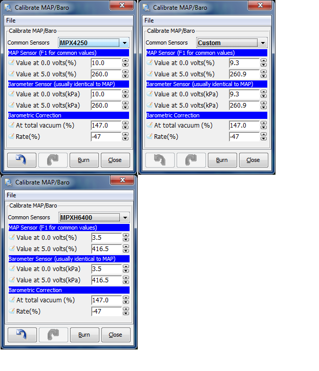
While I was modding the 3.57 and MS3X boards according to the DIY instructions, I went ahead and switched out the 2.5 bar MAP sensor with the MAP Daddy 4 bar sensor that was in my MS1. This will allow real time baro correction. When I calibrated the sensor I noted that the old settings did not match the 2.5 bar settings. I'm not sure if I had ever calibrated the sensor after I got the MS3. Settings for all three calibrations (4 bar, 2.5 bar, and custom - as delivered) are shown in the attached image. The "custom" settings were not too far off of the 2.5 bar settings and resulted in the MAP readings of about 5 kpa more than what I'm seeing now.
-
MS3 w/ MS3X Install - L6 turbo, sequential injection & boost control
Sam280Z replied to Sam280Z's topic in MegaSquirt
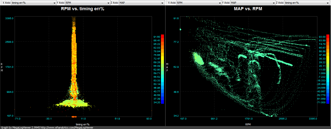
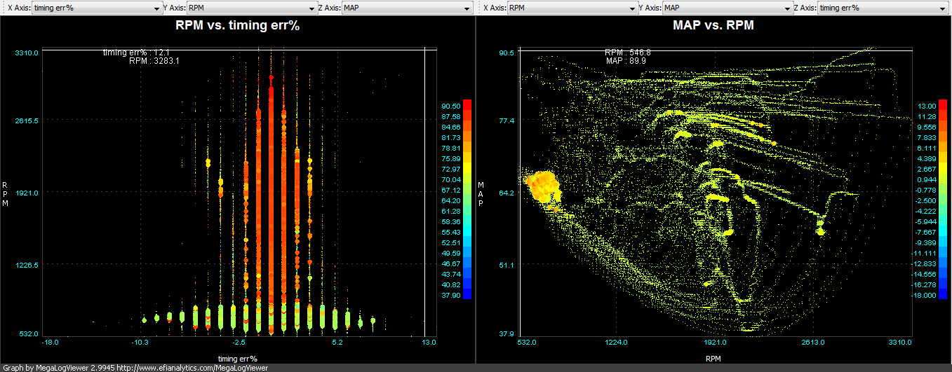
Got the DIY trigger wheel. Install Instructions Took just a few minutes to get it installed. Took a little while longer to get it started since I didn't put the center dist wire back. It is critical to turn off and back on MS3 between changing trigger settings. When it did start, it was advanced 50 deg. After a couple of tries I settled in on a tooth angle of 355.4 - not too far from the initial setting of 345. Idle timing is rock solid now. It used to bounce a lot. Setting the trigger angle was much easier and could be done at low engine speed. Engine smoothed out noticeably at low speed, especially under load. You can compare before and after graphs here: Old: New:
-
Who'd be interested if we made a L28ET trigger wheel?
Sam280Z replied to Matt Cramer's topic in MegaSquirt
Got mine yesterday and installed it this afternoon. Took just a few minutes to get it installed. Took a little while longer to get it started since I didn't put the center dist wire back. It is critical to turn off and back on MS3 between changing trigger settings. When it did start, it was advanced 50 deg. After a couple of tries I settled in on a tooth angle of 355.4 - not too far from the initial setting of 345. More impressions will be included in my build thread: My MS3 Build -
Cowl drain. There is a rubber tube with an attached grommet that runs from the bottom of the cowl, out that hole. You can see where it connects in the first picture behind the wire harness tabs. Sam
-
Who'd be interested if we made a L28ET trigger wheel?
Sam280Z replied to Matt Cramer's topic in MegaSquirt
I've attached a drawing of what I think I need to do. Can someone let me know if this should work? Thanks, Sam
-
Who'd be interested if we made a L28ET trigger wheel?
Sam280Z replied to Matt Cramer's topic in MegaSquirt
Thanks.should it be done on the 5V line like this: http://www.msextra.c.../optispark3.png? or 12V like this: http://www.diyautotu...iring_small.jpg with another 100kO resistor for the Cam pullup? -
Who'd be interested if we made a L28ET trigger wheel?
Sam280Z replied to Matt Cramer's topic in MegaSquirt
Thanks. That's good info. I'm also looking for the best way to wire the Nissan optical pickup: provide power and connect to the MS3 / MS3X. I shouldn't have to do anything to the MS3 or MS3X internally, right? Thanks, Sam -
Who'd be interested if we made a L28ET trigger wheel?
Sam280Z replied to Matt Cramer's topic in MegaSquirt
In anticipation, I've been researching how to wire the ZXT optical distributor with the MS3 & MS3X to utilize this disc. Currently I have the stock trigger wheel and have the dist wired as described in the DIYAutoTune webpage http://www.diyautotu...iring_small.jpg. This calls for a 1kohm 1/4W resistor on a12V source. In looking into it, there is another wiring scheme for the Nissan CAS, which I assume is similar: http://www.msextra.c.../optispark3.png. This calls for 330ohm resistor on the 5V TPS VREF source. The low res CAS still goes to the man Tach In on the MS3, pi n 24. The optispark code requires using PT4 (pin 31) on the MS3X for the hi-res (360 slot) CAS. For these trigger wheels, should I keep the low res signal wired as I currently do and add another 1000kohm resistor configured like the optispark option, but wire the (would be) hi-res signal to pin 32 on the MS3x? Or should I use the 5V TPS VREF and 330 ohm resistors and wire like the optispark, but use pin 32 on the MS3X? Or something totally different? Thanks, sam -
Who'd be interested if we made a L28ET trigger wheel?
Sam280Z replied to Matt Cramer's topic in MegaSquirt
Sign me up for two. Will they be available on your website? -
Missing tooth trigger wheel for the optical dizzy
Sam280Z replied to letitsnow's topic in MegaSquirt
Still trying to get something to allow better timing resolution and sequential. After I drew up the plans, Mario_82_ZXT offered to cut one on his waterjet. I shipped him the material, he cut it out, said he was sending it to me, and then disappeared. I haven't been able to get a response since Sept 28th. So then I pin my hopes on DIY. But an order SNAFU delays the part indefinitely. So I started searching and found something else. Only thing is: it does not have the missing holes. Will this one work (scroll down the page)? http://www.xcceleration.com/PP.accessories.htm Sam -
MS3 w/ MS3X Install - L6 turbo, sequential injection & boost control
Sam280Z replied to Sam280Z's topic in MegaSquirt
Thanks. It is a TWM manifold. From what I understand it is a Cannon copy. -
Who'd be interested if we made a L28ET trigger wheel?
Sam280Z replied to Matt Cramer's topic in MegaSquirt
Ditto -
using L28e for turbo build... is this a bad idea
Sam280Z replied to zero6zero's topic in S30 Series - 240z, 260z, 280z
http://forums.hybridz.org/index.php/topic/85185-n42-vs-f54-block-strength/ -
MS3 w/ MS3X Install - L6 turbo, sequential injection & boost control
Sam280Z replied to Sam280Z's topic in MegaSquirt
ITB w/ Boost http://www.msextra.c...p?f=131&t=40879 http://www.msextra.com/forums/viewtopic.php?f=131&t=42501 Dual Table ignition: http://www.msextra.com/forums/viewtopic.php?f=131&t=42373