Sam280Z
-
Posts
395 -
Joined
-
Last visited
-
Days Won
4
Content Type
Profiles
Forums
Blogs
Events
Gallery
Downloads
Store
Everything posted by Sam280Z
-
Trying to find a source for 1.5mm head gasket for L28 turbo
Sam280Z replied to Sam280Z's topic in Nissan L6 Forum
Thanks Tony. I'll order one tomorrow and let everyone know what I find. Sam -
I recently blew the head gasket on my ITB turbo L6. I'm pretty sure that the root cause was an assembly error by the idiot (me) who put the motor together. I assembled a 1.5mm MLS head gasket from layers from two gaskets, one new and one used. Out of ignorance, I put two shims together and two embossed layers together instead of alternating them. It ran like this for over a year, with no symptoms except extremely slow coolant loss. Last week it finally gave out and combustion pressure clearly was getting into the cooling system. The motor hydro-locked overnight. I did a leakdown test and found that cylinders 3 & 4 leaked between themselves and the coolant (see videos in album linked below). In the album I have pictures of the piston tops and combustion chambers before and after cleaning. https://plus.google.com/photos/110595327894846974778/albums/5819204301794009809 To me it looks like light detonation has removed the gloss from my JE pistons . I also need to work on my throttle synchronization as evidenced by the varying shades on my exhaust valves. I thought I'd get the opinions of those with more experience than I before I reassemble. Thanks, Sam
-
As the topic title says, I need a 1.5mm head gasket for my L28 P90a converted to solid lifters and spray bar turbo motor. I need this ASAP for my daily driver. I've searched and called around with depressing results. Cometic says theirs will not work on a turbo motor because it does not have the oil passage between 3 & 4. It seems like it will take weeks to get a Kameari. Does anyone have a source for a HG that will work and I can get quicker than that? If you want to see my pain check out https://plus.google.com/u/0/photos/110595327894846974778/albums/5819204301794009809 Thanks, Sam
-
I'm running that Koyo. It is nice. Bolted in no problem. Only thing is that it uses a smaller cap and they claim that it has all the stock mounting locations. Unfortunately, that is just boilerplate language and there are no shroud mounts. And Tony, If you can get them that cheap,I do hate you. Sam
-
I too found that the car ran without the optical pickup grounded (by accident). I didn't leave it that way though.
-
Sleeper, Check out my build thread here and my other threads on msextra. I had crazy sync loss problems. Turned out to be non-resistor plugs. Make sure you have really good spark plug wires, resistor plugs, and all sensor and MS grounds are in a single location on the engine block. Sam
-
Check your valve lash too. Too tight will result in low readings by holding the valve open too long. There are too many variables in a compression test to make the absolute values of the numbers worth much. battery voltage, starter speed, all plugs out?, throttle open?, etc... I prefer leakdown tests to compression tests for these reasons and the fact that if there is a problem, you know what it is. Sam
-
You can have the head straightened before it is cut. When looking for someone to work a warped P90 a couple of years ago, I had a local shop claim they could straighten it and take less than 5 thousands off. I ended up using a different head that was already straight - but his option was there... Sam
-
Sleeper, For future reference, the crankshaft bolt is center drilled to accept a puller and the head is smaller than than the crankshaft snout diameter which allows the pulley to be pulled over it. Just screw the crankshaft bolt in and use the puller - no washer needed. sam
-
I can think of no reason to have to install the distributor driveshaft one tooth off. I would verify the timing mark on your damper. Put a drinking straw in the #1 sparkplug hole and turn the motor by hand until the straw is at its max height and the #1 cyl cam lobes are pointing up (valves closed). Is this the damper you have: http://www.summitracing.com/parts/PFS-80055/?rtype=10? Part number 80055? That damper is for many applications (L16, L18, L20B, L24, L26, & L28). The timing pointers may differ on these engines. Ignition advance has a HUGE effect on vacuum. Sam
-
If it ran fine with the Z31 ECU, it should work fine with the MS3. Verify that the distributor gear is installed correctly - it should be set as stock. While you are at TDC, it is a quick check to verify that the cam timing is correct as well (although I doubt that is your problem if it ran fine before and nothing mechanical was changed). If the distributor timing gear is installed correctly per factory manual, I'd center the distributor hold down bolt in the adjusting slot, lock it there and focus on getting your Tooth #1 Angle correct. (Mine is set to 229.3). You do not need to turn the distributor to set the timing. The software will figure out where the engine is and fire the coil at the correct time. You just need to make sure the rotor is pointing in the right direction. When setting the timing, make sure to switch the fixed advance setting from use table to use fixed timing. I like to set it at 15 deg when setting the Tooth #1 Angle. (make sure trigger angle/offset is set to 0) It really helps to use an advance timing light. Why are you doubling the VE and halving the req fuel? MS3 has plenty of resolution - in my experience, this should not be necessary. Sam
-
L28ET - Suddenly 0 oil pressure (Not a faulty gauge!) *SOLVED*
Sam280Z replied to tyson's topic in Nissan L6 Forum
Years ago my ex-wife's mustang had an intermittent and random loss of oil pressure. Turned out to be a sometimes partially and sometimes completely clogged intake screen. I always push on the oil bypass valve when I change the filter to ensure that it is not stuck and will operate in the case of a clogged filter. Sam -
I performed this repair a few months ago and it has been working fine, so I thought I'd report here. The low level warning lamp lights when current is allowed to flow to ground through a small thermistor located in the small metal can located at the end of the metal rod protruding from the fuel level sending unit. Over time this component fails - it appears that the electrical leads corrode away at the thermistor. If you can shake the sending unit and hear a rattle in the can, the transistor has failed. When you open the can, you will find a small ceramic disc. A thermistor's electrical resistance changes inversely with temperature - higher temperature results in lower resistance. Also, it heats up when current flows. So, when this thermistor is submerged in gasoline, it stays cool enough so that not enough current can flow to illuminate the warning lamp. When it is out of the gasoline, it starts to warm up and allow current to flow, illuminating the lamp. I used Mouser part #: 527-2004-1k Manufacturer Part #: RL2004-582-97-D1 You will have to pry apart the little can and solder the new thermistor in. While I was in there, I noted that the contact on the fuel level sender wiper was basically worn away. A small drop of silver solder on the end of the wiper and it seems to be working fine again. Sam
-
L28 teardown, weird stampings - crank & pistons
Sam280Z replied to Chunky's topic in Nissan L6 Forum
To answer your last question, you can lift the crank out leaving the rods/pistons in. -
It can't rev without air.Something is letting the air in.
-
If it is reving that high, air is getting in somehow. Make sure the throttle valves are closed enough. It should not run at all if the throttles are completely closed. The linkage can cause one or more carb to hang open a bit (since you haven't balanced them yet). Check for intake leaks - missing gasket, twisted o-ring, missing plug... Sam
-
I don't know the specifics off hand, but different years had different pulley widths as well. You can swap clutches, however.
-
Are you aligning the dist shaft like this? I use the rear edge of the top dist mount screw hole and the front edge of the bottom dist mount screw hole - a straight line drawn through those two points should be parallel to the tang on the oilpump driveshaft. I'd be surprised if it ran well before with the Z31 ECU if the shaft was not installed correctly. Are you sure you are looking at the trailing edge of the contact? Remember, the dist turns counter-clockwise. You can also set the #1 cyl at the max advance you would run and see if the contact lines up. Complete lack of spark at the plug could be something else entirely. There is a lot of voltage and it wants to go somewhere - usually to the wrong cylinder - which occasionally would be #1. If the oilpump shaft is installed incorrectly, I would still expect it to have spark, just at the wrong time. Try putting the timing light pickup on the coil wire to be certain it is firing. Sam
-
The factory setting for the oilpump shaft is correct. If it was working before, it will work now. Set the distributor like it was and see of the rotor contact trailing edge is lined up when #1 CYL is at TDC on compression stroke. Just turn the distributor to set it like this. Leave the shaft alone. Sam
-
You don't want the rotor centered at TDC. The rotor has a wide contact because there is no advance mechanism in the distributor. The contact has to be aligned at all desired advance angles because the ecu will determine when the spark occurs. Old distributors with mechanical and/or vacuum advance should be centered. They tend to have smaller diameter caps and narrow rotor contacts. You should have the trailing edge of the rotor aligned with the cap at TDC. This will allow the earlier (advanced) spark to occur when the rotor is aligned somewhere along its contact face. From your description, I'm not sure what you are changing. The trigger angle should be set to zero. Do not use it at all. Set the Trigger Wheel Arrangement to "Single Wheel with Missing Tooth". You should be changing the Tooth #1 Angle, not the trigger offset (which should be set to zero). Add or subtract the error you see on the timing marks from the Tooth #1 Angle to move the timing light indicated timing to match the software indicated timing (set with fixed advance to the value of one of the marks you have on the timing pointer). I can never remember which way moves it advanced or retarded so I just use trial and error. I do not use the trigger wizard and I'm not sure it is even applicable for setting the tooth #1 angle. Remember to reset MS after every change. Sam
-
Paint the timing marks white. Bend the indicator or attach a piece of wire with the end painted white so you can get close to the damper mark. It is a pain, but really necessary if you want to be sure of your timing. Stick a straw down the sparkplug hole to see when the #1 cyl is at TDC and both cam lobes pointing up - then align the marks by bending the indicator. (I used a degree wheel and a positive piston stop, but that was before the engine was in the car.) Time spent on prep will save countless hours chasing the unknown. I highly recommend getting an advance timing light. It will save you a lot of trouble. Are these the instructions you are following? http://www.diyautotune.com/tech_articles/using_diyautotune_nissan_trigger_discs.htm You should use these settings. They work for batch as well as sequential. I've run both with the DIY wheel. Did you wire the cam input? If not, I guess you could ignore the cam specific settings but I have no direct experience. I'm triggering on the rising edge as per the instructions. I don't know why my angle is 120 deg out. I have verified that the orientation of the wheel is correct and the oil pump gear is installed correctly. It did run fine with both the 280zx wheel and the DIY wheel with the angle specified in the instructions as long as I was using the distributor. It was just when I attempted to switch to COP that it messed up and I had to change the offset angle by 120 deg. Sam edited to fix link
-
Yes. 280ZXT distributor. I didn't use the trigger wizard. I changed the Tooth #1 Angle in the Combined Ignition Options dialog box until the actual and indicated timing matched. (I ended up with the 229deg value) It really helps to have an advance timing light. Make sure the Trigger Angle is set to zero. Make sure to cycle the MS every time you change settings. Use Fixed Timing as the option under Fixed Advance in the Combined Ignition Options dialog box to stabilize the timing so it won't be jumping around following your advance table. I set it around 15-20 deg to get a strong idle while setting the offset angle, then switch back to table. (If you are using a regular timing light, you will have to trust the advance marks on the timing indicator on the front cover. It also would not hurt to verify the crank pulley timing mark. The outer ring has been known to rotate - upsetting the indicated timing. If you are using the distributor to distribute the spark, your timing can be off in 120deg increments because the coil doesn't know which cyl it is firing and the cylinders fire every 120 crank degrees. (as long as the rotor is timed appropriately -set the #1 cyl to TDC and make sure it is pointing at the #1 post on the dist cap). Coil on plug is a different story. You should not have to rotate the distributor to set the timing - especially since it ran befiore. Be sure to follow the trigger wheel instructions form the DIY site. HTH, Sam
-
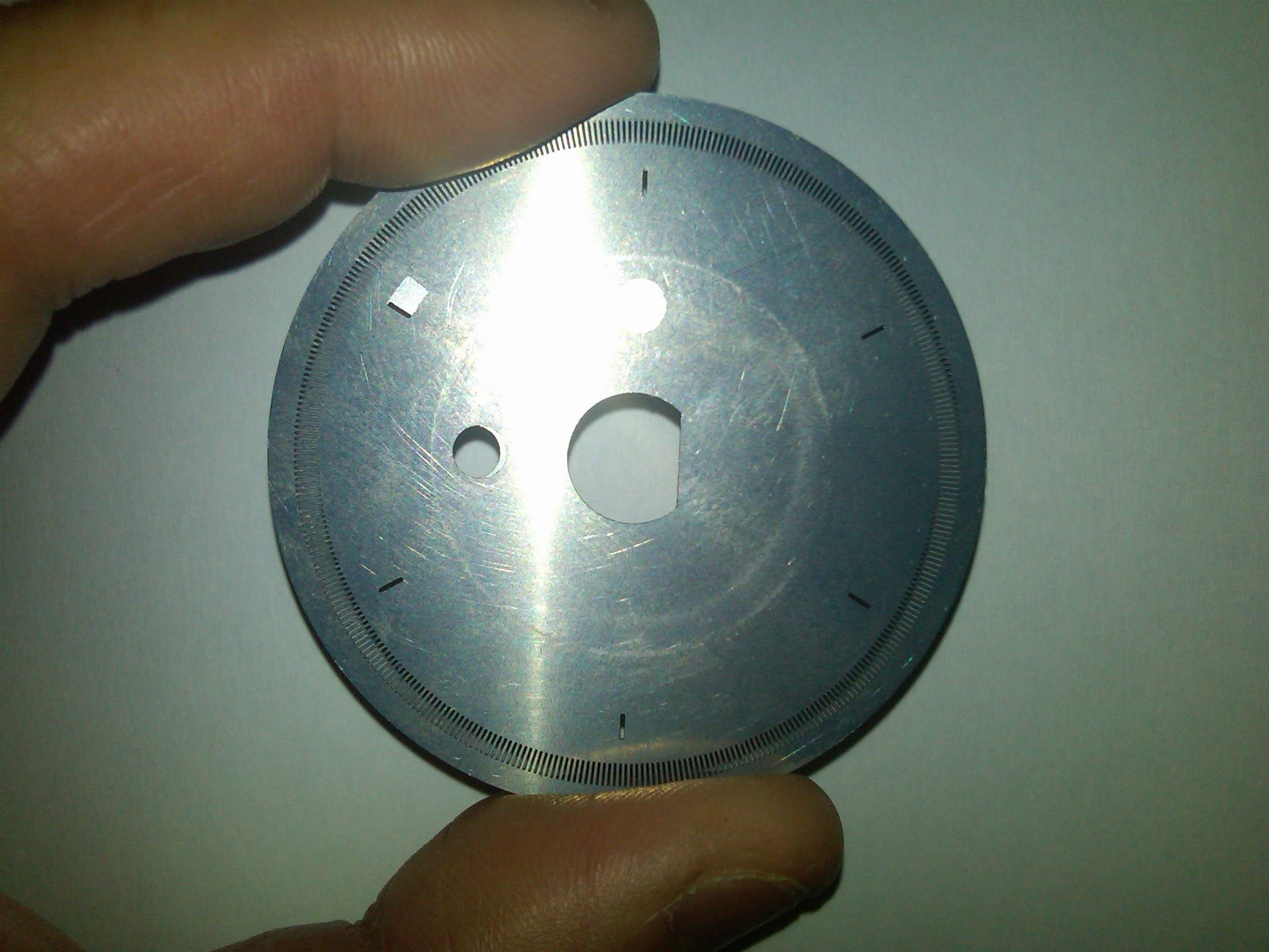
Sleeper, I've attached a photo of the 300zx wheel on top of the 280zxt wheel so you can see how the slots line up. The 300zx slot is not supposed to be centered - as it is not in the photo: Regardless, using the wheel as trigger only will just affect when the coil fires, not if it fires or not. I like the DIY trigger wheel better than the stock wheel because it gives better timing resolution, but it may not solve your miss problem. Some things to check (I learned most of these the hard way). 1- Make sure you have resistor plugs and wires. I'd even ohm out a plug to be certain. 2- Route the trigger signal wire away from the plugs and wires. 3- make sure your grounds are all run back to a single point. Sam

-
MS3 w/ MS3X Install - L6 turbo, sequential injection & boost control
Sam280Z replied to Sam280Z's topic in MegaSquirt
It appears that the problem was the use of non-resistor plugs. See my post at MSExtra: http://www.msextra.com/forums/viewtopic.php?f=131&t=45296 -
I am using the 3.57 board configured like this: http://www.msextra.com/doc/ms3/ignition.html#vrv357pull (V3.57 board - VR Input with pullup for hall sensors, optical sensors or points) I was using the stock 280ZXT wheel before i switched to the DIY wheel and it worked fine. Do you have yours set up up like this? http://www.msextra.com/doc/ms3/ignition.html#vrv3pull (V3.0 board - VR Input with pullup for hall sensors, optical sensors or points) That should be the equivalent to how mine is wired. If you do this, I think you do not need the pullup shown in the DIY diagram as it is on the board. look at the instructions on the DIY trigger page as well (except for wiring the MS3X cam input and software settings). http://www.diyautotune.com/tech_articles/using_diyautotune_nissan_trigger_discs.htm Sam