
Derek
-
Posts
1337 -
Joined
-
Last visited
-
Days Won
48
Content Type
Profiles
Forums
Blogs
Events
Gallery
Downloads
Store
Posts posted by Derek
-
-
It's amazing what you can find with a little digging!
Alright now I'm sold on the sealer idea. Good enough for the "majors", good enough for me!
And the data sheet from the MFG (I think)
http://www.achesoncolloids.com/NR/rdonlyres/02BD7E6E-0BC8-41C3-93AC-EAA59144426A/0/Dag213.pdf
I'll do some more digging and see if I can locate it in a little larger quantity.
Derek
-
Check out this link to a patent.
http://www.freepatentsonline.com/5640942.html
Scroll down to the description and it sheds a little light on it.
Never heard of pre-sludging before.
Derek
-
The BMW stuff is what I am referring to, IT IS NOT RTV!
This is the same stuff Nissan uses on it's own throttle plates. Trust me, unless you get a throttle plate THAT STICKS SHUT you will not be able to make it seal at an angle that won't stick off-idle. The grey 'paint' lets the throttle plate seat at an angle slightly less than metal-to-metal fit---which will prevent sticking. Anybody ever get a TWM big-throat that STICKS? I did. Brushing in a sealant kept it from that annoying habit. I got mine in a small applicator-in-cap bottle from the aforementioned NISMO Employee (now former NISMO Employee...)
It done dried out and it was 'generic'---he had a bigger source in the shop, but he just brought me the small bottle.
It has to be the BMW stuff...if one person can get it, anybody can get it.
That is the stuff I'm talking about. The sealer makes your life WAAAAAY easier. Metal to metal will gall. Metal to metal will wear.
You need something to 'soft seat' onto, and make a nice seal. Paint does that. I'm thinking it's an epoxy matrix with graphite in it. Kind of like the coatings they spray on oil-free screw air compressor screw elements....hmmmm... that gives me another possible source. I gotta call Mike in Buffalo now...
Aluminum against aluminum would be really sticky. Hot aluminum is even worse. The fact that I have aluminum against stainless will help. When I cut the plates on the angle jig the leading and trailing edges will have a chamferd edge that will aid in sealing.
My plan is to get the best fit I can without the sealer. I'm then going to put the whole rig into an oven and let it heat soak. Then I'll check the fit and stick on the plates.
At least that's the plan for now subject to change without warning!
My client who makes the hot rod parts also told me about offsetting the throttle plate on the shaft. This lets the engine vacuum help seal the plate in the tube when it's closed.
More stuff to chew on!
Derek
-
heres a site with some information on a black sealant that BMW uses on their throttle plates.
http://www.westcoastriots.com/htmlfiles/obd1.html
maybe you can contact them and ask them for a BMW part number of some kind, but I don't see why Kinsler wouldn't have something they can recommend.
If these products are hard then that could create problems on their own. My throttle tube is machined stainless. There really aren't any imperfections other than the ones I put in after the fact by mistake. I think my main problem is the inaccuracies in the machining of throttle plate. I talked to one of my clients who makes injection systems and carb parts for vintage hot rods. I described my angle jig for machining the throttle plates and he said that's exactly the way they did it.
I guess for all practical purposes if I waxed up the throttle tube and painted the adhesive on the butterfly while it was closed then the adhesive/filler would stick to the plate and not the tube. This would create a sealed edge for sure.
Derek
-
might try this stuff. permatex #29132
I've used it several times for similar issues on carburators. its awsome because its the only stuff i've found that resists gas and solvents unlike other silicone gasket makers. it might be the same as the nissan stuff. its also grey.
That looks like what Tony was talking about. The specs are certainly in line.
Thanks
Derek
-
update?
Nothing much happening. Buried in work right now.
But boy do I want it!
Derek
-
Hi Joe
Great looking setup!
I'm casting my own ITB EFI manifold. I have an L28 with an E88 head. I'm trying to figure out my injector sizing and thought I had it nailed until I saw your post. The calculators I used are calling for a larger injector than the 14LB your using. I'm not quetioning your choice I'm wondering if I'm thinking a little too big. Can you give me a little info on how you made your choice?
Thanks
Derek
-
I've lived in Florida since 1968. I grew up here and learned to drive here. Rain and wet roads are a fact of life. The road conditions are poor and there's always one road or another under construction. If your only doing 5 over the speed limit you sure as hell better be in the right lane, so we don't consider 75 in a 70 speeding. A maneuver that you've made hundreds of times on wet roads before suddenly becomes an out of control spin for no apparent reason. It's happened to me a few times. It happened to my dad and he defined the description "slow and cautious".
To me this would be tantamount to me criticizing some one in the north for loosing control of their car on a frozen road.
We don't call it "Florida ice" for nothing.
Jeff posted his experience here so people could gain from it, and because he wasn't contrite enough for some of you, some posters decided he was a menace to the roads. Most of you did it in ways that were guaranteed to elicit the types of strong responses you received. You can wrap it phrases like "tough love" or "trying to make you a better driver" but all it does is turn discussions into flamefests.
Derek
-
Holy crap that's a little harsh. maybe you should try some decaf.
One of the few times I wish I was a moderator!
Derek
-
I will second Bryan's comment of shooting for NO gap. The bypass is your idle control. Frank280ZX just went through this on his ITB setup and wasn't getting an idle below 2300, after screwing them down to even a paper-thin opening (like less than 0.003" cracked, it was still idling the car at 1700 rpms.
Normally a fixed bypass orifice sets the 'no stall minimum idle speed' (say 700rpms) and the IAC makes compensations ABOVE that point---so even iwth an IAC, you are wise to incorporate a fixed or variable bypass orifice from the external air source to keep the IAC working near it's seat, instead of much wider open...makes for better and smoother PID control of the IAC when your A/C kicks on (or whatever). Working the IAC near seat keeps air velocity up and helps prevent buildup. You will be cleaning your IAC if you don't have a good air filtration setup!
EFI is designed to idle with the throttle closed for maximum intake manifold vacuum off-idle. You can always make a non-linear throttle actuation to help tip-in form a low idle, but you will play hell trying to get your idle down to reasonable levels with the six throttle plates open.
A simple 1/4" vacuum hose is what I have controlling bypass air to all my engine, and with a reworked 82/83 NA idle air bypass needle valve through that 1/4" hole I can raise the idle to over 2200rpms easily. They don't take any air at all to idle!
Kinsler throttle plates, why make the jig...they're cheap!
Hi Tony
I'm absolutely not going to have any air gap on the butterflies. I can see the cumulative effect of a little gap on each one time six! I can also see the benefit of having the bleeder.
I'm in a catch 22 situation on the butterfly jig. In order to make this manifold work I have to make the jig. If I go to the trouble of making the jig I might as well make the butterflies. I called Kinsler and they want $16.00 each for the butterflies. $96.00 is close to the tipping point anyway for me to MFG them.
Can you go into a little more detail on this:
I heard you could get the same grey sealant that was OEM on the Nissan TB's for total sealing once the T/B is staked to the shaft. Nissan guys got ahold of some, ideally that is the way to go, than way you can use a slightly 'loose' butterfly and minimize the chance of Sticking when it gets hot or loaded with debris...like some of the TWM bodies are known to do...
Thanks
Derek
-
Go with the vintage air kit. It replaces the heater and fan assembly. I'm running one in my 73. It's been in the 90's in Florida and it's cooling the car with no problems.
Here's a link I posted on it.
http://forums.hybridz.org/showthread.php?t=133709
Derek
-
Aw Jeff that really sucks. Is this going to affect your move?
On the bright side you get to get rid of that Rustoleum roller job!
Call me Monday if you get time.
Derek
-
You are gonna want NO gap, or atleast plan for not gap, or you will never get your idle down low enough. The best way is to have no gap, and do all of your idle controll through a bypass valve. I have build a few ITB setups for L28's, and it is always a pain, getting everything syncronized and timed correctly. What is the ID of that machined hole where the Butterfly has to fit? I ask this, because you can rob butterflys from other throttle bodys, with the same id, and it already has the cam, built on the butterfly, and the two holes, and you would be ready to go. How do I know this? Because I came accross the same dilema a few years ago, when designing ITB setups for these motors.
I'm controlling the idle with a IAC. The bores are 1.495. I just need to get through this one as I'm going to buy pre-made butterflies from Kinsler if I do any kind of production. They have a 1.523 as a stock size and they'll make any size you want. I'm also going to make everything work with their throttle arms and shafts. No need to reinvent the wheel. Their stuff has a really nice old school feel and will work well with the style.
Derek
-
You do know, that butterflys are NOT round correct? You can make them on a 4 jaw, or a buck chuck, but will require a few setups, to make them in a lathe. They would be easier to be made on a mill, yes it can be done on a manual mill, with rotary tables, but I would do it on a CNC.
Yep I'm aware of the oval shape. If it's round it won't close as well and has the potential to stick. My problem is my mill isn't as fresh as it was when it was new. It has a little backlash and while perfect for pattern work trying to make a butterfly fit properly is a bit of a problem. I'm thinking of making a mandrel for the lathe that has a 14 degree face on it and 2 screw holes to hold the butterfly blank. I'll machine the blanks a little oversize in the mill and then screw them to the mandrel and make a finish pass with the lathe. This should also cut a knife edge on the leading and trailing edge of the butterfly.
In theory this should work but of course we all know I live in theoryville!
I wish I knew how much gap I could get away with but I figure it's easier to do it right and just be done with it.
Derek
-
Anybody remember the old CAN-AM or Formula cars with their stacks all askew? That's what this reminds me of, I love the look!
The performance and sound are frilly intrinsic benefits for motorheads!

This is exactly how I describe my design concept to my friends. Like the "old CAN-AM cars"
I guess I got pretty close then!
My God.... It's full of STaRZ!.. Derek, that's an amazing manifold. please please get it going soon, the suspense is deadly... all I can say is WOW.For the back triple I guess it wouldn't work to cast the same upside down. since the Injector bosses would be on the wrong side then. Perhaps in the production casts, you could make them swapable. Though I suppose it's just as easy to make the 2nd cast unique..
So once these are figured, what would a ballpark cost be if say we wanted to order a set?
Phar
"pardon my drool..."
Making the patterns for the rear manifolds aren't that big of a deal. All I do is mirror the design in the 3D program and add the additional bosses.
Since there seems to be a fair amount of interest in this thing I'm making some changes so that the machining can be a little easier.
The cost is going to be a little pricey. Most certainly more expensive than the TWM setups. But I like to think your getting a lot more for the money!
Thanks again everyone for the kind words. It really does help on a large risky project like this.
Derek
-
Looks incredible. I wish I knew how to do castings.
Just wondering, will the back be the same as the front? If so I think you might have some clearance issues between the two middle airhorns.
Luke.... trust your instincts in the 3d solids program. Alright, after looking at the pics again you made me go out and check with a square against the head. I'll have about 1/8" between the center horns. It sure looked like it was going to be collision city though.
Can you refresh my memory as to why you went with vertical throttle shafts?Because the throttle bodies come in at different angles along the horizontal plane, having horizontal shafts would be a real pain to machine. And besides I love the look of the linkage on the top.
Repeat after me, form first function second!
Derek
-
First off I know I could have picked a nicer head and valve cover but this is the best I could come up with.
This is probably the last I'll be doing on the manifold for a month or so. I'm super busy right now and in this economy I better get while the gettings good.
I will be doing the final design on the rear manifold in the meantime.
Derek
-
I 'd be intrested once they are perfected.
Thanks guys. The biggest compliment you can get is someone interested in buying your product.
I will be selling these assuming it works to my expectations. I will say though that it won't be a budget manifold. There's a lot of hand work that goes into this thing.
Derek
-
those are fantastic. And are going to sound pretty nice ( understatement methinks ) as well.
Are you going to try to blend the shape of the throttle butterfly rod into the butterfly ( i know that sounds newb but then... I am ! ) ? So it has some sort of flow around the rod.
In any case very very inspiring work.
Yea I can't wait to hear them run.
At this time I don't have plans on streamlining the shafts. If I start producing these I may increase the shaft size to 5/16" diameter. this gives me more options on pre made components like levers and such.
Derek
-
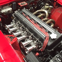
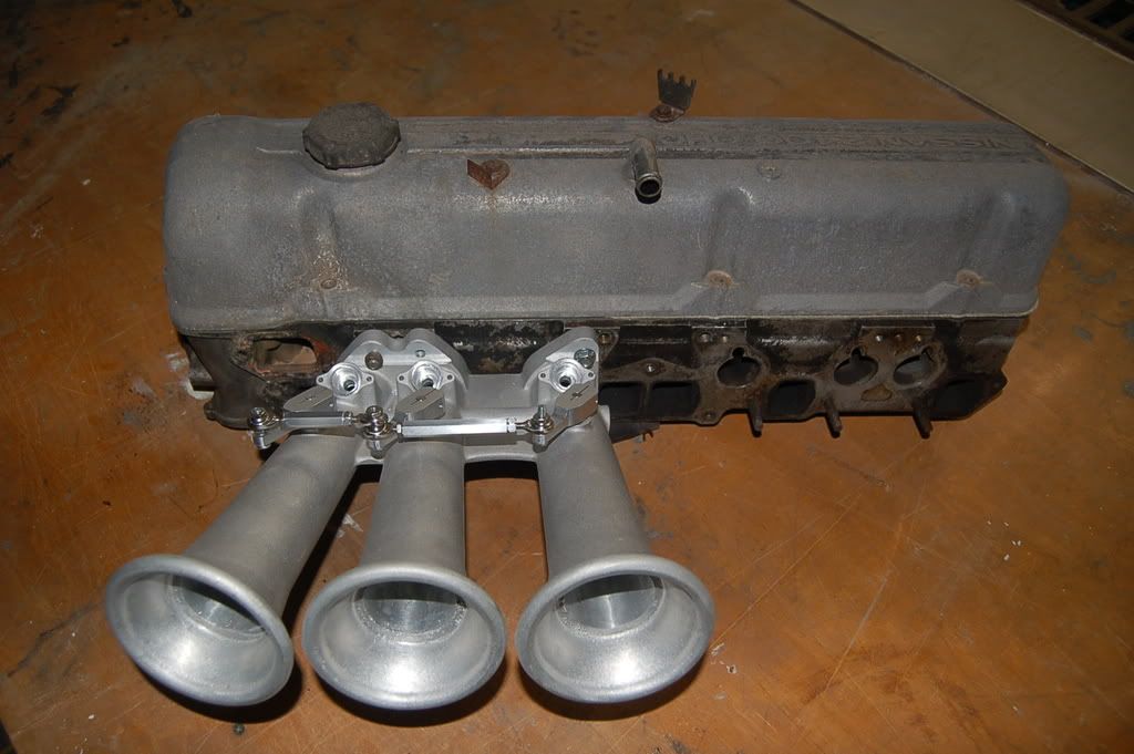
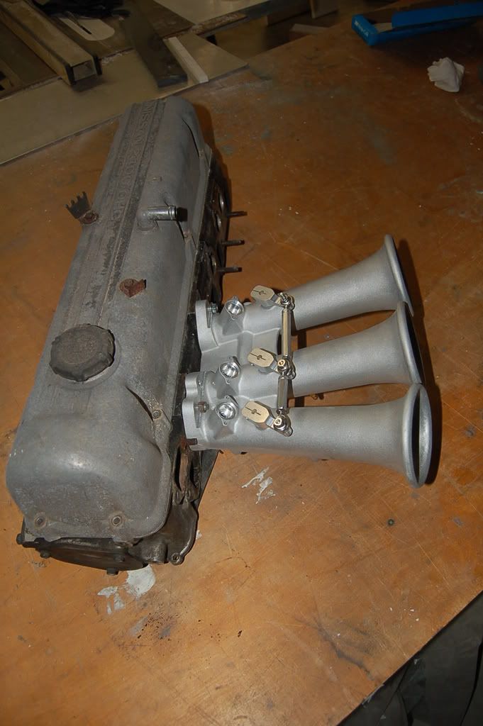
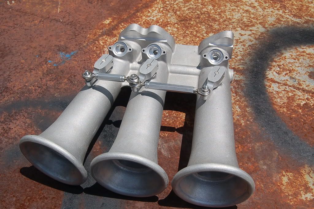
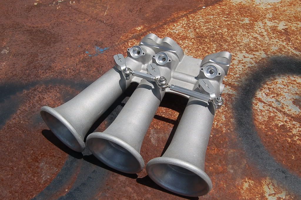
I think I have everything mocked up at this point.
Here's a shot of the linkage with the throttle closed.
And open
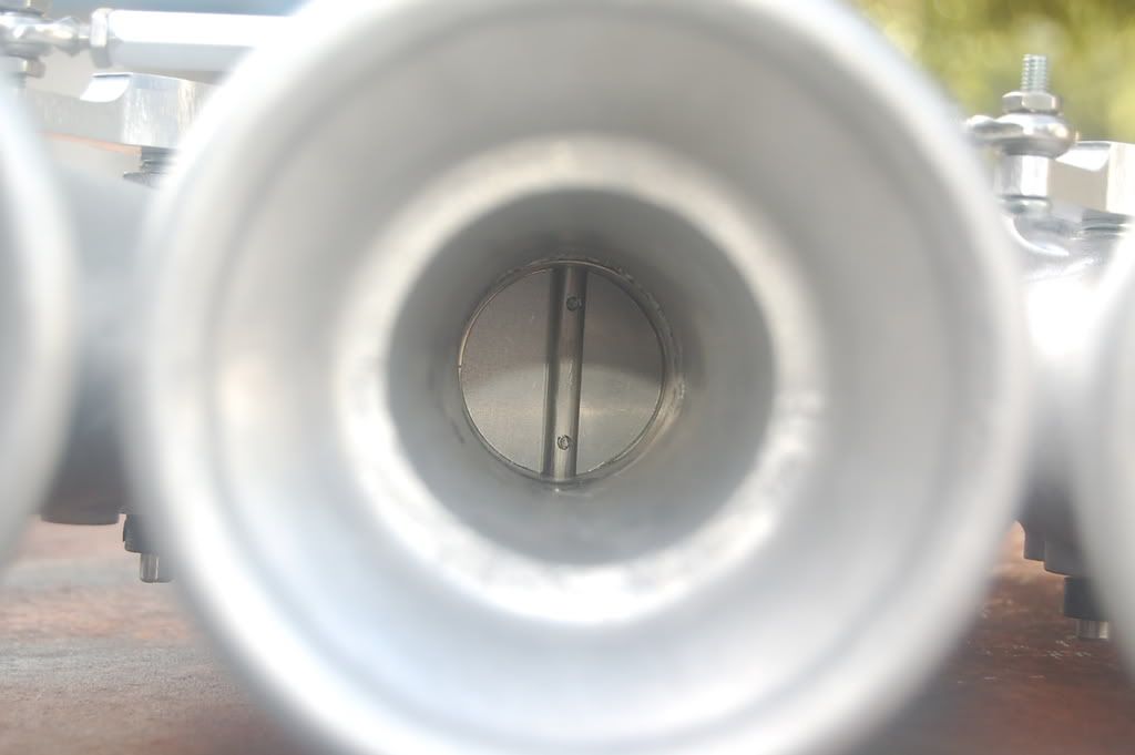
This is just a practice butterfly. I need to make a jig for my lathe so I can make these as a turning operation. Milling them just isn't giving me the results I want.
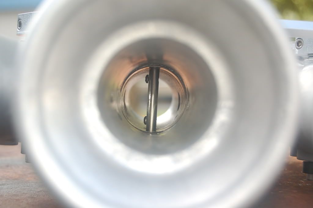
Say AHHHH
And yes that is a giant step between the casting and the throttle tube. I have a fix for the next manifold. I just need to figure out what I'm doing on this one.
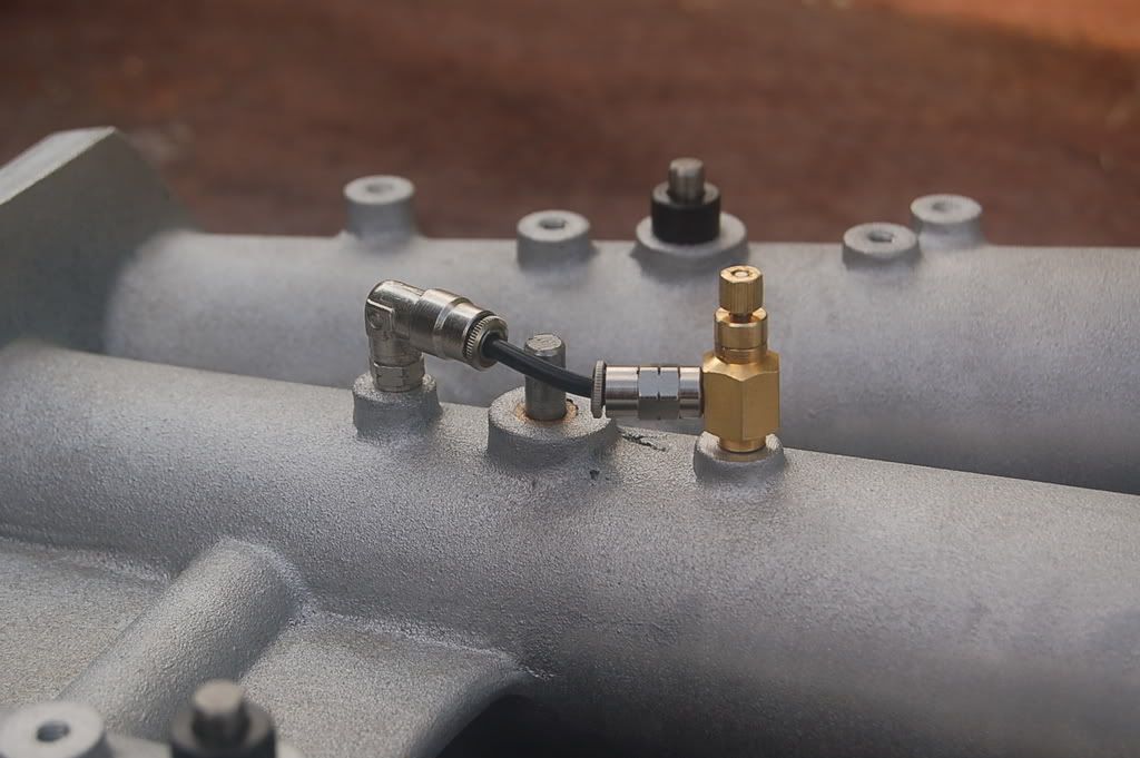
This is the vacuum bleed for synchronizing the venturis. I need to lower the rear boss. Also the throttle shafts will be shorter. It looks a little shabby this way.
At this point I think I have enough info to finalize the design for the rear manifold.
Now all I need is time!
Derek
-
hey, ross machine has a drill bit that they sell that will make the injector holes a one-gun ordeal.
costly bit at 120 bucks, but if you plan to run these... and your customers find out what you're really doing, you can make back your customers lost time!
Yea I looked at those. They're nice and if I had a manual mill I'd be all over it. With my CNC mill though it's just a two step process. I drill the through hole with a drill bit and then orbit in with a 3/8" end mill to cut the injector bore, o-ring pocket and injector clearance pocket.
Ain't technology grand!
Derek
-
You are building an extra one for me Right?? lol You know im gonna find another z and want to build a nice NA motor!!! lol
Yea sure thing. I'll bring yours with me on Saturday!
It's a good thing my customers don't read this forum. I've got about 10 other things I should be working on right now!
Derek
-
Thanks for the feedback guys.
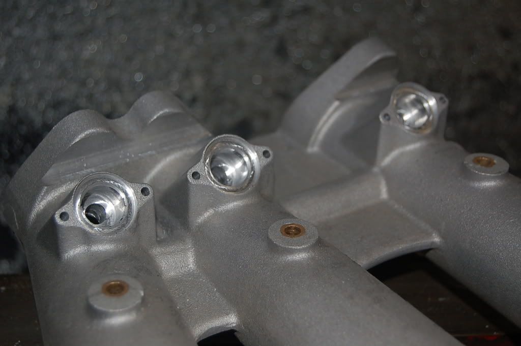
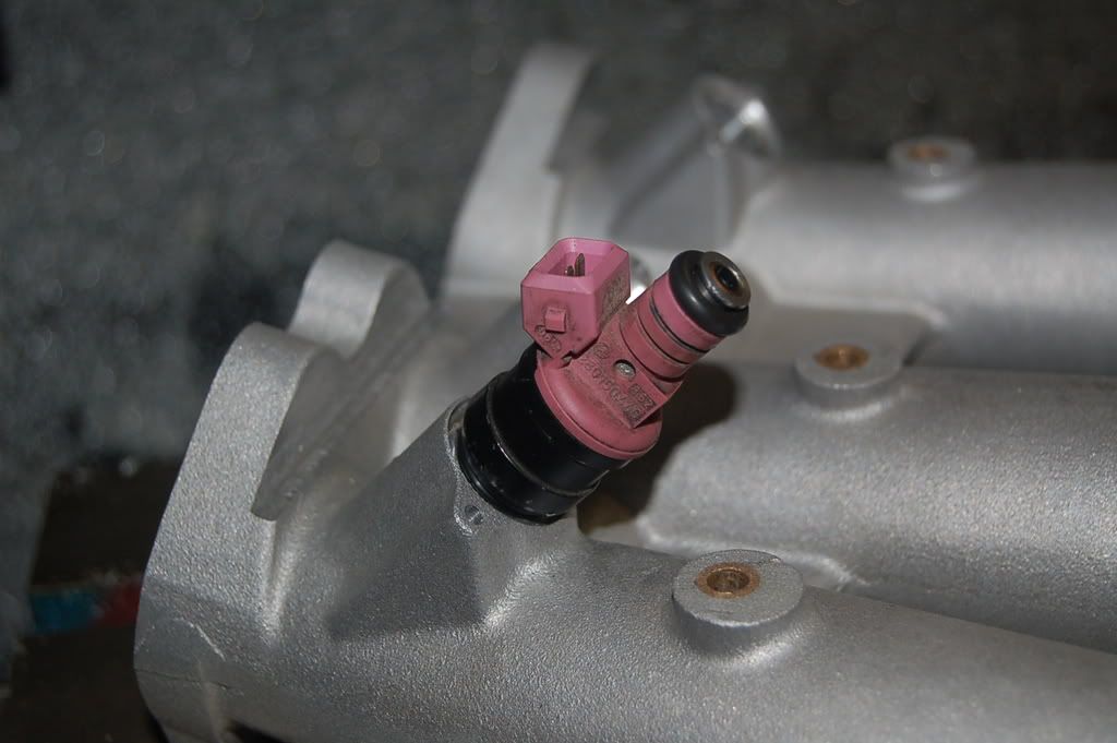
I had a delay of game on a pattern so I decided to knock out the machining today. It went really well. I'll make a few adjustments in the next pattern to make things better. I was trying to get some info on injector boss dimensions and settled on making a smaller hole through the runner and larger hole in the boss for the injector. I removed the cap and o-ring from the bottom of the injector and I'll use an o-ring on the shoulder of the injector for sealing.
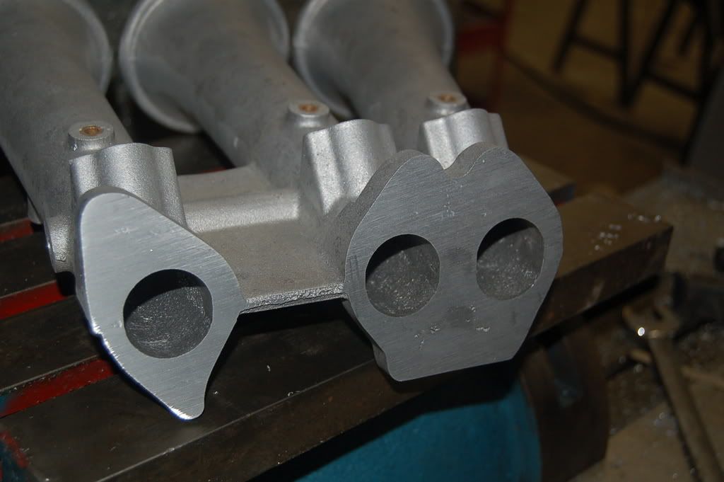
I machined the flange at 14 degrees which I think is the right amount. I'm borrowing a head this weekend so I can start mocking everything up. I have enough meat left on the flange to re machine it if necessary.
I ended up with an inclusion on the flange but it's shallow and won't affect anything.
The ports are under sized so I can match them to the head.
Next I'll be machining the throttle shafts and butterflies.
Derek
-
Wouldn't some turbulence help the fuel spread out better in the chamber? Don't mean to answer a question with a question. Sorry.
I was wondering that myself. It must not be a big problem as I can't find any posts regarding it on the web.
Derek

Making my own EFI intake... The First Casting
in Nissan L6 Forum
Posted
Wow nice find!
Unfortunately they appear to be in France. Now do that same search magic for a place in the states and I'll really be impressed!
At this point I'll probably buy a couple of kits from the guy on ebay and see if the stuff works. If it does the job then I'll try and source a larger quantity if I go into production.
Thanks
Derek