-
Posts
637 -
Joined
-
Last visited
-
Days Won
1
Content Type
Profiles
Forums
Blogs
Events
Gallery
Downloads
Store
Everything posted by ozconnection
-
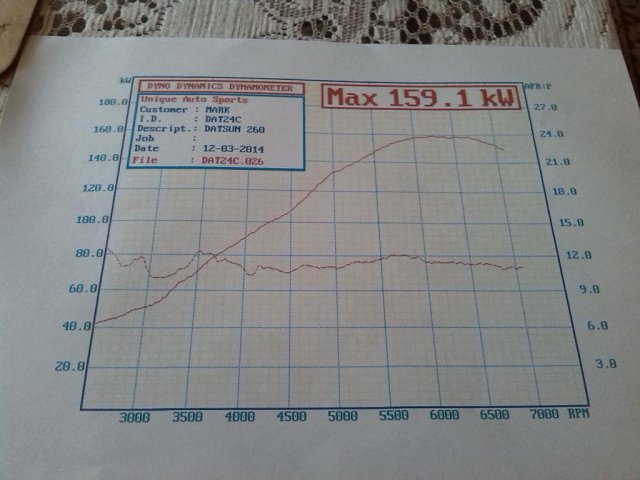
I got serious and managed to get a final figure of 159.1 rwkw which converts to 213 rwhp. NA. Megasquirt. There's certainly nothing too wrong with the Clifford if it can support this much power. Ignition is standard 280zx dizzy, 20 deg. static with 30 total.
-
Hi there, I'm wanting to try an aftermarket cam in my L28 and need "200" lash pads throughout. Where the stock pad sits nicely within a stock retainer, aided by the recess under the lash pad which lets the pads be better supported by the retainer's shoulders, rocking motion of the lash pad is minimal. Without measuring it, the contact surface (between the ears) of the lash pad and the top edge of the retainers (shoulder) is 20 thou or so, there shouldn't be any possible contact between the rocker arm and the retainer. With the 200 lash pad, there is considerable rock when sitting it in the stock retainer, due to a flat bottom on the thicker lash pad and relatively little support by the shoulders on the retainer. I have aftermarket steel retainers. They do provide support for the thicker 200 lash pads, but are too tall in that the top edge of the retainer its about 20 thou too high and above the top, contact surface of the lash pad. The other issue, is that the installed height of the retainer/valve springs is higher than with the stock retainer, extra valve spring shims will be needed to restore correct seat pressure on the springs. I know, welcome to world of hybridz, aftermarket cams and valvetrain mods....no big deal and I'm happy to proceed and perform whatever work is necessary to make this project come together. Howevever, 1) the head is on the engine 2)do retainers with different 'shoulder' heights exist that I can simply purchase and use without modifying those I already have and 3)can I use the '200' lash pads with the stock retainers? Will the pads be too big and render the rocker gear unreliable ( max rpm's will be 7000 rpm) Thanks for your input.
-
What type of accelerator pump diaphragm valve do you have on your Holley? I had the best results with the umbrella type found on the more modern bowls. The older style with the captive ball bearing isn't as crisp and takes time to seat and the shot delivery lags behind the throttle opening. Is there a phenolic insulator between the heat shield and the carb at all? I love this thread....
-
What the hell is that Tony? I know I haven't been around for a while but that thing looks like....FUN!! Thanks for the advice on what style of injectors I might try, and the theory and practise on 'homogenizer screens' Interesting idea!
-
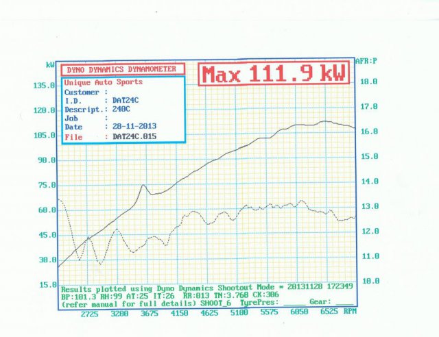
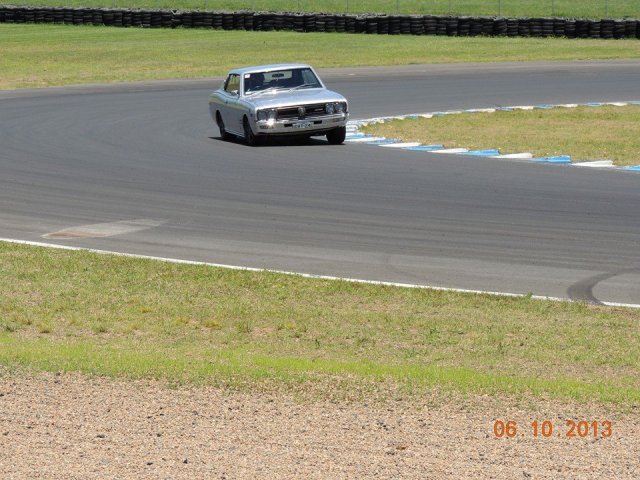
Love what's happening there Super Dan. I recently did some work on the dyno and netted 111 rwkw with a mapping and a tweak to the cam timing. The operator of the dyno suggested a few things to try, my setup needs better injectors, the Seimens don't atomise finely enough, the mapping needs to be done with an N-Alpha (tps) and the phenolic insulator needs to be ditched. A heated throttle body would dramatically help with fuel mixing with the air in the vicinity of the TB. My injectors are outboard of the throttle, so atomisation here is VERY important. He also removed the vacuum line to my Malpassi regulator because of the erratic mapping on the VE map it was causing. Tuning the fuel curve seemed much easier after this little mod. Very happy with it overall, works really well on the track
-
Excellent news!!! I have some updates myself and will post them up later today. (At work ATM)
-
Those diagrams are well done Blue72! You do know that there are even more ways the water hoses et al were routed on L series engines? Cedrics had water from the water tap on the block under the manifolds at the rear of the block feeding the heater box in the cabin. I don't see this on any of the zeds. What does this mean? Dunno, apart from just pointing out variances and therefore options should one be required.
-
A similar problem with my LC-1. No end of trouble with it and chased my tail for weeks. Junked the LC-1 and ended up buying an Australian Tech-edge unit (2CO) and had absolutely no problems with my wideband since. Consistancy seems to be the main issue surrounding the Innovate units. Sometimes they work, sometimes they don't. PAINFUL.
-
If I were to show you these two dyno runs again, that were done on the same dyno on the same day and were to look at just the AFR curve (the lesser curve) of both, could anyone guess correctly which is the carburetor engine and which was the EFI one? WTF is going on here?
-
'Tractive effort' was used to describe it. Had it written on the bottom of many of my earlier (older) dyno runs. 600 posts!
-
I don't follow. The X -axis on both graphs is in Km/h and there is no torque table as far as I understand it. The 'lesser' curve in both plots is A/F ratio. As far as RPM's is concerned, the sedan run was done in second gear lock on the auto. The ratio is 1.542 and the diff is 4.11, tyre is 205/70/14. The coupe was done in 4th gear, 1 to 1 ratio, diff is 4.11 and the tyre is 205/50/16 BUT. don't rely on the the dyno's speed calibration, they are often very wrong. I wish it could just read rpm's on the x axis as well.......
-
-
I put the coupe on the dyno (rolling road) and a friend of mine posted this vid on Youtube/Facebook for me. Here's the link. http://youtu.be/4IpzjwGZbpA Final figure was 106.7 rwkw (143 hp).
-
Thanks Tony, The small port head engine made just under 100 kw, it was the coupe that made 106,
-
A visit to the local dyno as part of the Sydney Datsun Club sanctioned event allowed me to run both of my cars. Significantly, the sedan with the L26 P30/Y70 combo almost busted out triple figures today, maxing out at 98.4 rear wheel kilowatts. I'm very happy with that. My old N42/N42 combo, which is in my mates Cedric wagon with manual transmission pulled a best of 88 rwkw. (My car is an automatic as you may recall.) The dotted line on the dyno charts are air/fuel ratio measurements taken from the tailpipe. The old Holley on that engine is doing a pretty good job out there. Compare it with the Megasquirted EFI L28 AFR's and it looks even more impressive. The revs on the dyno graph are just on 7000rpm. At 6400rpm, the revs were slamming against the MSD limiter and I pulled out the pill, at that point power was strong and not falling off as expected. That little Y70 is doin orite! The coupe was put on the dyno today too and put out 106.7 rwkw's which is pretty good for an 8.3 compression engine with a stock "A" grind cam. The head is the P90 with 1mm over intake and exhaust valves. Won a trophy for that effort. Yay! Datsun heaven......
-
You bet it does!!! Great to see someone else moving in this direction. Tell me about your throttle body, injectors, intercooling, management, turbo, compression, cam, head and bottom end configuration, Oh heck, tell me EVERYTHING...please! Looks awesome mate. Cheers. Ps. Xnke was very patient with me and I have the car running well based on his advice. There is certainly more work to do with megasquirt, getting it to run factory smooth but I just ran a round trip to Phillip Is. from Sydney (2500 kms) which included some track time and I was very happy with it. Heat shielding is very important, my fuel was getting hot and the tune was changing on longer drives. It's better now.
-
Yeah, thought about that one years ago....funny that no-one has got one and posted a pic or vid of it. BUT, how much would you really see with all that oil up there. At idle it might be ok but. Cool idea!
-
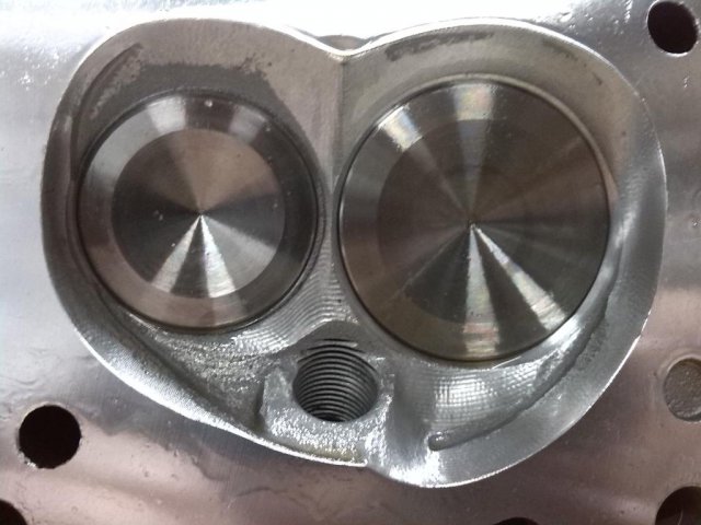
I appreciate your response Gollum. Is this the first time you've ever read this thread? I thought you may have wanted to interject your thoughts sooner to have created a more balanced or rounded topic discussion. BUT, you have now, so thank you. With the Holley vacuum operated 4 barrel (leak, LOL), my P30/Y70 combination works very nicely. The small cylinder head ports help with mixture velocity and homogenisation is improved. AFR’s are very smooth and consistent, with less ‘jumping around’ seen with the N42/N42 engine. In addition, the design of the intake manifold (Arizona Z Car) lends itself to promoting low rpm torque by having a split plenum, SMALL plenum volume and relatively small runner diameters (but larger than the ports in the Y70 head). I mention the manifold trends here and I will contrast them with the Clifford 6=8 manifold shortly but the split plenum design in the Arizona creates a dual plane arrangement where the cylinders are essentially broken into two groups with alternate firing in each bank that relies on wave harmonics to assist with cylinder filling. This plenum type of manifold configuration may be considered by many to be a poor choice of induction on an inline engine when it lends itself nicely to IR type induction setups. Sure, but I’m not comparing my setup with them. I’m exploring my options with what I already have in my collection of parts, somewhat limited but specific in terms of my end application. I mention a small plenum with the Arizona manifold. That might be thought of as a liability but I’ve found that this manifold is extremely forgiving, I could run a mechanical secondary 390 cfm Holley with the N42/N42 and could almost get away with it. I would have to first bring the engine rpm’s up to around 3-3.5k rpms before I could just nail the throttle. Excellent on the freeway with kick down!! When the N42/N42 was replaced with the P30/Y70 combo recently, I could just nail the throttle at any rpm’s even off idle without any fear of flat spots or bogging. (the tuning was never completed for this carb so there is even more to be had from it potentially. The L26 now runs the well tuned vac. Sec. carb. as was used with the N42/N42 engine). The Clifford intake is a single plane design with a very large, open plenum and it’s extremely sensitive to carb size and would bog even with a poorly calibrated vac sec operated carb and it was just hopeless with the mechanical secondary version. The plenum volume is paramount here with a WET manifold design. I know from real, firsthand experience that wet manifolds need to have small plenum volumes for good torque BUT for maximum power, with the throttle fed progressively, the Clifford will give more top end horsepower. (Dyno tested and verified by me several years ago). I could be scientific and measure the cross sectional area/volume, their port runner diameters etc for both manifolds but for argument sake, let’s just assume that the Arizona manifold is designed for torque and the Clifford with its open single plane configuration is built for top end power. My point is that the transition from atmosphere through carburettor to the plenum area of the manifold is quite different in both manifolds at this crucial point. If air speed in this area is governed by the volume it has to ‘fill’ and is drawn from, then it’s no wonder that fuel will fall out of suspension with the Clifford manifold when sudden wide open throttle applications are made. It’s too big and there is too much surface area. Some here will quote the X-Tau layer, laminar and turbulent flow etc but this is the scientific part of the argument that’s somewhat beyond explanation here. There is a point of ‘recovery’, that is the 4 or so inches of manifold runner that finally ends with the manifold bolting onto the intake side of the head. Experimentation with a stock N42 head, where there was match porting of the runners with the head would indicate no acceleration of air speed at this point. The use of a small port head (eg Y70) could again work to step up gas velocity in the port area and past the intake valve and into the cylinder, further increasing mixture homogenisation by the step down from runner to port and past the intake valve on its way into the cylinder. Gas velocity is only at its highest at the point of most restriction once beyond the throttle blades. The EFI manifolds you mention increase the velocity of the inducted air at the wrong time, leaving the manifold at high speed and only to slow down again slightly because of the ‘larger than runner’ diameter and thus volume, port (actually made worse by enlarging the volume of the port ie porting). EFI manifolds have a rather large plenum volume in comparison with the wet manifolds. Importantly, all runners connect to this plenum without division or separation so therefore by definition, must be considered a single plane manifold. Little effective resonance takes place so it’s only by virtue of the small diameter runners that torque levels at low rpm are enhanced BUT become a flow restriction at higher rpm’s. We know this. Nothing new here in regards to the factory EFI manifold. Enter, however the P65 EFI intake manifold for the Nissan L Series sixes. I’ll let Tony recount his experiences with this style of manifold. The factory did acknowledge the ability to maximise torque through runner length and so these manifolds exist. I have one, complete, at home. Its runner diameters match EXACTLY the diameter the ports in the Y70 head, thus no step up or down exists at this interface. No turbulence, just laminar flow at high velocity to promote cylinder filling and provide excellent torque characteristics on the small, two litre six cylinder engines that motor 1420kg Cedrics. Now I want to apply that same ‘advantage’ to the L26-28 engines by only using the final part of the equation, the Y70 head. In the future, I may wish to experiment with the P65, but I’m in the middle of ‘something else’ at the moment. The exhaust system is generic: interference style, square port and is followed by a 2.5 inch pipe with two mufflers. That’s on the P30/Y70 engine. I would love to spend the time and money developing a better exhaust for this engine but funds are limited and so is time. Although perhaps not optimum, there is an acceptable exhaust sitting under the car ATM. Compression ratio is good 10:1 in the P30/Y70. That’s got to help but I don’t want to get overconfident and build a ‘miscalculation’, something that I have to go to lengths to counter. Ie water injection, colder plugs, retarded ignition, octane booster etc. APITA for anything other than an all out race machine...even then there are better ways to go about it. Thermal management is extremely important, as I just found out in my Megasquirted 240C coupe. Fuel was getting too hot and my swirl pot was warming up. The tune would change after long drives because the fuel was becoming less dense. On the freeway, it would lean surge and the AFR’s were telling me the same story. I made a heat shield. Nothing fancy but I wanted to make sure nothing else melted!! (The fuel rail sits an inch above the TPS wiring) I’ll see how that turns out.
-
LOL, but you said retarded Mr D. "Special" is an entirely different thing...DUDE! LOL
-
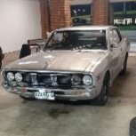
Electric fan thermostat switch location
ozconnection replied to 280Z Turbo's topic in Nissan L6 Forum
I've bought and used a simple computer temp switch which triggers at 70 deg Cel. IIRC. It's a NO switch and has a 2 to 3 degree hysterisis. I use it to trigger a relay to power my engine fan. I place it high on the radiator but now I use a second one in parallel about halfway down. I had a coolant leak at one point and the switch didn't activate because it never came up to temp. The lower one compensates for a low coolant level if it happens. No cutting, just some wiring required which is simple to manage. The switch came from Jaycar in Australia and is only a few bucks....cheap as and it works. I'm sure you guys will have something the same or very similar. -
Some more than others, it seems. LOL
-
I was forever telling my mates years ago that "In America, the L series engine..." Now I can say, "In Australia, we can build..." thanks to people like Peter and co who are finally pushing the boundaries for us 'down under' About time.
-
Yes Richard, these guys have a good reputation. Getting the head developed the way I want it is only just a question of money...better start saving!
-
The summary here on port velocities is interesting and I have no reason to doubt what you're saying Xnke. Indeed, my ports will run out of flow once gas speed approaches V.Max but this phenomenon isnt happening at silly low rpms, at 6000rpm, I'm looking for the next gear anyway. If we look at cfm figures for the small port heads, the intakes flowing about 120cfm, and not allowing for percentage volumetric efficiency losses (100%) on the intake side of things were flowing 720cfm. Thats Holley 4 barrel territory. If we work with 80% VE, then we flow 576cfm. If this is what the engine can flow taking into account flow and induction restrictions, then its not the ports that are restrictive but the rest of the induction system that's not optimised. (I'm talking Arizona Z car/Clifford four barrel dual/single plane type manifolds here guys, NOT IR intakes!) This is probably why almost nobody uses these manifolds for racing, they can't flow what is needed to get the power that is seen with IR induction setups. There are other reasons too but that's a discussion for another time. It's a flow thing... The intake port/valve combination is only part of the induction system. Do I need bigger ports/valves when the rest of the induction system can't seem to match the flow potential of the head? Whats the point in putting more effort in the head then? Regardless, the small ports seem to do the job at the desired rpm ranges it most commonly sees. (I might add that during my drag run with Dave, I was hitting the rev limiter in second at 6250rpm. It wasn't a wall there either, just it was time to shift because I'd hit the limiter on my MSD.) In a few weeks, Dave and I are attending a Club day on a local chassis dyno. I can't wait to post those figures up so we can compare the two graphs to see what's happening where through our different engine and driveline combo's. Cheers.

