SidWell
-
Posts
171 -
Joined
-
Last visited
Content Type
Profiles
Forums
Blogs
Events
Gallery
Downloads
Store
Everything posted by SidWell
-
Yes you can certainly do that. The issue is that you then have to have the harness hooked up and installed in the car. You then either have to adjust the spark plug wires or rewire the connector. My aproach, while crude, only involves the coil box and can be done on the bench.
-
I got the information below from the V3 EDIS sticky. It was posted by BRAAP. The pic below is of the 36-1 spinning under the strobe of the DBtoZ timing light and the camera was able to capture exactly what we saw. Note that the spark was actually occurring at the trailing edge of the 6th tooth. We were under the impression it fired in the middle of that tooth. __________________
-
Yes you got the idea. Make sure the volt meter is set on the lowest possible setting.
-
If you are not sure about the input wiring, this is a very crude option will help you find out what goes to each coil. It requires an analog multimeter, (an oscope would be even better) some wire and a 1.5 volt battery. Do not use your car battery or anything with a lot of current capacity. A "AA" battery may do just fine. Hook up the multimeter across one set of spark coils. Hook the wires up to one of the input trigger pins and the other to pin 3 (the common leg). Set the multimeter to a very low voltage sensitiviy. Quickly touch the battery to the input wires and release it. Do not continuously hold the battery shorted to the input coil that will burn it out. You should see the meter or oscope deflect at the moment of contact and then when it is released. If it does not, move to the next spark coil set. I am not sure if the AC voltage setting will see the single pulse. If you have it on DC voltage it will only deflect when the battery is either touched or released. If you have a digital multimeter you may or may not see anything at all depending on the sample rate. Like I said, This is very crude, but it should help you to mark which input pin goes to which coil. Warning! The coils wires are quite fragile when not used for their original purpose. Think of them as a cross between a light bulb and a fuse. If you run too much current thru them for too long a time they will all burn out. A quick touch and release is all you need to do the job. Because this is nothing more than a specialized transformer it is the application of voltage and release of voltage that cause the deflection.
-
this link may help you. The key to your answer is in the photograph at the bottom. Make sure you have the Mopar connector. Match the wire colors on the connector to the red, black and white square patches painted on the coil pack. http://forums.hybridz.org/showthread.php?t=133381
-
Datman, How bout zipping up your .msq file and posting it? I have a non-stock N/A, EDIS engine and would like to compare notes.
-
I finally found the config setting that will allow viewing the O2 sensor reading while cranking. In Fuel Set-up, Other Fuel Settings, there is a setting called Max Cranking speed. If your setting is greater than your crank speed, the O2 sensor will not be active. If the Max Cranking speed is less than the actual cranking speed you will see the O2 sensor responding. I spent way too much time trying to figure this out.
-
I have put a scope on pin 14 of the CPU and watched the trigger from the simulator. I hooked up the MS and watched the pulse while it cranked. I set the stim to the same crank rpm and verified the pulse form. The stim is a narrow pulse that drops from 5V to zero and then goes back up. The input from the EDIS is a square wave. The down-going pulse is at the same location on the scope. The CPU is reading the tach pulse as RPM. I am also looking at my O2 sensor on pin 28 at the same time. After about 30 seconds of the MS operation the voltage goes to 5V. When I crank the motor, my O2 Lamda continues to read 0.5. When I run the stim the Lambda reading tracks the voltage with no problem. Could there be a setting somewhere that is preventing the reading from being read? It all looks like it should be working. I have gone over my config but it all looks like it should. Any ideas? Here is my .msq zipped up. megasquirt200808091547.zip
-
I like the location of the boss. If it works for you I will be in the market for a mount like that. Rossman, want to separate with one of your brackets?
-
KTM... If you still need a reverse nut, try McFadden-Dale Hardware. They are in Anaheim near the 91 & 57 juction.
-
Thanks for clearing the A/C issue up for me. My bracket does not have the boss you are refering to. If you are going to use the two extractor tap holes, be sure to make very beefy stand offs. Remember the pulley will be spinning up to 6K rpm or over. That would be a very bad time for the trigger wheel to start to wobble.
-
Are you going to remove your A/C compressor? In your first post you say you have an A/C compressor. In your last post you talk about mount the VR pickup to the A/C compressor boss. I don't know where you are going to find room on the compressor side of the engine with the compressor in place. Take lots of pictures. I want to see how you do it. I have A/C as well and wanted to put my VR pickup over there but could not figure out how to do it. I also want to see how you mount the 36 - 1 wheel behind the pulley.
-
You may have installed a polarized cap in backwards. Usually if the cap is polarized there is a + on the positive leg. Check the value of the resistor you installed. You may have accidently installed a 100 ohm resistor where a 10,000 ohm resistor should be. I have not looked at the board for the resistor value. I only say 100 and 10,000 as an example.
-
It looks right. Before you apply the power to the MS take a few minutes and power up the relay, take a multimeter to pins 3 & 5 and make sure it is closed. I would suggest that you learn a bit more about the relay you have. Specifically find out how much current it is rated for and where you can find a replacement.
-
That is the problem. The car won't start. If I need the tach pulse to trigger the O2 sense, and I have the EDIS CAS wired backwards or wrong, I may not be getting the correct tach pulse and the car won't run and the O2 will not be sensed. I thing I need to go back over my EDIS and CAS wiring again.
-
When I hook up the LC-1 directly to the laptop, I get a lambda reading of 22.8. I believe that this is what it should be reading in open air. By the way; the O2 sensor did work properly until I rewired the engine bay. I have gone over the wiring several times.
-
I can watch the voltage change from .3 volts before it is warmed up and after about 30 seconds I see the voltage go to 5V on pin 20 of the relay board and on pin 28 of the cpu.
-
Innovative LC-1 WB sensor and controller, Megatune 2.25p3, V2.88 code. My Lambda readout is constantly zero when hooked up to the LC-1. The voltage in free air on analog 2 output is 5 V when measured at pin 20 on the relay board as well when measured at pin 28 of the CPU. I have the EGO sensor set to single wide band. The AFR calibrator has been set to both Innovate LC-1 and also manually entered as a generic wide band with 0V = 7.35 and 5V=22.30. At no time do any of the air fuel mixture readings indicate anything but the minmum reading. Even the real time display shows zero in the O2 graph. Easy you say... pin 28 on the CPU has failed, or the firmware is bad. Well, here is the issue. When I hook up my stimulaor board and run the voltage up and down on the O2 potentiometer, I see the voltage change on pin 28 of the cpu and the O2 reading changes on the display. When I manually put 5V on pin 28 while the stimulaor is running the O2 sensor maxes out. All other sensors such as tach, tps, air temp, water temp all work properly when it is installed in the car. I reflashed the eprom today as well. Any ideas?
-
You can try flashing the processor firmware again. That would be the easiest thing to do. The only other option if you do not want to go romping around inside the ms is to veryify all your grounds. A bad ground can cause many different issues. Go to the latest documentation and verify your grounds on the relay board are set up exactly like the drawing shows.
-
It turns out that my LC-1 was bad. I now have a new one.
-
Assuming you are refering to the JP2 terminal block, it provides +12v to the injector coils. JP1 Terminal block pins 1 thru 4 provide the ground thru a couple of power transistors inside the MS box. When the transistors are switched on, they ground the +12 thru the injector coils causing them to inject the fuel. If you are refering to the JP2 terminal block, Yes. To make it easy, wire from pin 1 on on JP1 thru the injector coil and current limiting resistor if you are using one, to pin 1 on JP2. Pin 2 on JP1 goes to pin 2 on JP2 and so forth. Since I have an L6 engine, I put 2 wires on pin 1 and two wires on pin 4. I left pins 2 & 3 with a single wire to reduce the chance that the middle conductors could some how become shorted or cross connected to each other.
-
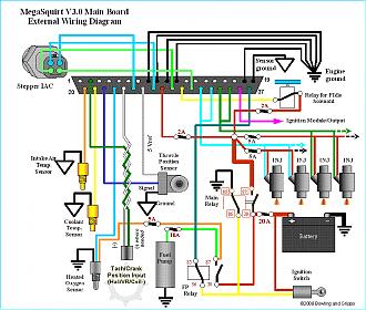
Are you hooked up per the latest drawing info at http://www.megamanual.com/v22manual/mwire.htm#rb ? External Wiring with a V3.0 Main Board Because of the added stepper IAC, ignition control, and PWM idle capabilities of the MegaSquirt-II, the V3.0 main board has been designed with these functions in mind. As a result, five additional connections are made at the DB37 connector. These are shown below: Note that you should read the appropriate section of the MS-IITM EFI Controller manual for the V3 board - it contains much more wiring information that may be important for your installation:

-
Under load, eh? That is when the injector drivers are working the hardest. The power transistors for the injectors could be heating up and failing. You might want to replace them. Do you have access to any Freeze Spray? Open the MS box locate the suspect transistors and when the unit fails, spray the suspect transistors and see if the car starts again.
-
this is the mounting method that I used: http://forums.hybridz.org/showthread.php?t=135616 I have yet to figure the best mounting point to attach a third mount to the bracket, however. I am toying with the idea of drilling and tapping a hole into the timing chain cover. I need to figure out how to keep it from leaking though.
-
:hijack:Darn it Tony! I have just spent an hour looking and messing with the slipping crank pulley you gave me some time back. Now I only have more questions than answers. The only answer I have is yes it is possible to mount a Ford EDIS 36-1 tooth wheel to the stock 81 ZXT CAS trigger wheel. The middle pulley is larger than my stock pulley. This drives my A/C unit. Is a larger pulley acceptable? Why is the rubber dampner between the alternator pulley and the pulley mount? Why is it not hard mounted like the A/C and P/S pulleys?