

Oddmanout84
-
Posts
658 -
Joined
-
Last visited
Content Type
Profiles
Forums
Blogs
Events
Gallery
Downloads
Store
Posts posted by Oddmanout84
-
-
You can file the ends of the rings, to make the gap larger.
Well, I have a ring filer wheel, but it has the unfortunate inconvenience of only taking material away from the rings and doesn't add it!

If my gaps were smaller than spec, I'd have no problem at all grinding them down. Unfortunately, they're a bit larger.
Based on the number you posted at .005 per inch comes out to an end gap of .017. I can't feel .003 difference with a feeler gauge. I'd put it together and not think twice about it. That's about all the help I can offer.
I hope so. I'd like to imagine that it wouldn't make much of a difference either, but I'm trying to keep tolerances as tight as possible. Guess that's why I'm freaking out about it all. At worse I'll just end up with a lot of blowby and oil burning?
-
Any anecdotes on ring gaps used? Oil consumption issues?
-
So I'm rebuilding my shortblock and after all my clearances for the crankshaft have checked out well, I moved on to gapping my piston rings. I remeasured each bore (overbored the F54 block .50mm last summer) with a bore gauge and vernier micrometer with the garage temperature at about 50*F, and came out with a 3.409" bore. That's about 86.58mm, where the machinists bored to based on my 86.5mm ITM cast pistons and me telling them it was going to be turbocharged to 20psi max. There were no specs or instructions written on the box of pistons or the supplied rings.
I have not been able to find much about the rings online, either. The boxes have no brand label on them whatsoever, but thankfully they do have a part number: SWN30066-2 CYL. Searching around discovered that this in an NPR part number, but still no specs. I looked up average gap specs both in my Datsun rebuild books and on the internet.
The rebuild book says between .013" and .017", for stock engines.
The "How to Modify your Datsun OHC" book says .004" gap per inch of bore, up to .002" more for high power engines.
Online sources from Wiseco says .005" per inch (.0055" per inch second ring) for street modified turbo/nitrous.
This site: http://www.aa1car.com/library/ring_end_gap.htm says .0045" to .005" per inch for a street performance engine.
When I squared my first top ring into the bore, the smallest feeler gauge I could fit into the gap with a light drag was .020". Using the equation above, that's about .006" per inch of bore, which puts the gap into the recommended for "race only" category in just about all the sources I found. ****. I'm wondering, is this way too excessive? It sure seems like it, seeing as I intend to use the engine for a hot street car, not full blown race. All of the pistons are really just similar to OEM cast specs, except they've got Swaintech coatings. The most boost I plan on running is about 20psi (when I replace the stock turbo with a T3/TO4E).
I'd have a hell of a time returning the rings, since the box set they came in with the pistons was purchased on ebay over a year ago. The only other option I guess would be to find another set of L28ET rings meant for a .50mm overbore, and even then are they going to fit my current pistons (if the ring manufacturer was say, Nismo or Perfect Circle)?
Or am I really just flying off the handle and .020" is a good gap to go with?
-
I want to build a custom down pipe for my 1981 280zx. I need a flange that will fit the stock turbo. Does anyone have a flange for sale? Or know where to get one?
Ebay. Should be a 4 bolt T3 flange with 2.5" ID.
-
Are you sure you want to bump the compression up that high? From my understanding (unless you're running very high octane race gas), using flat tops in addition to a 1mm head gasket and E88 head is going to result in an extremely high and likely unmanageable ratio. What's your current measured CR with the dished pistons?
-
Cannonball89, it looks nice but why run the cold pipe behind the radiator?
It works better if you have the drivers side be the cold pipe so that it is only an S bend to the throttle body.
How is that setup wrong? Its exactly as you describe it should be. The cold side is going directly to the throttle body.
-
Sounds like a vacuum leak to me.
-
Fix that rust first!
-
I hate to be a downer, but unless those coatings on the pistons are baked on, I can't help but comment on what a bad idea that looks like.
In answer to your higher oil pressure question, there are spring and shim kits sold to adjust oil pressure. You should be able to get your hands on a DL Potter kit for a good price on ebay.
-
There is a setup on Blackdragon auto that works really well. Just modify the mounting point on the bottle and you're set to go. Very easy, inexpensive, works excellent.
-
So.....this got a little out of hand. I guess I won't share little projects anymore.
If you never try, you will never fail.
-
I will give this thread yet another bump for its useful information.
When I got my turbo motor, the stock turbo on it was plumbed for water cooling, but there was little indication that the fittings were ever used. The line coming off of the coolant inlet was about 3" of hose mysteriously capped with a coarse thread bolt. Thermo housing only has two threaded holes left now with two NPT plugs blocking them. I had been curious as to if this was the proper way to plumb the turbo, and now I know.
And knowledge is power.
If I ever do that cylinder head cooling mod, that will mean I have used every single port on that thermo housing!
-
Because after power washing about 5 times the surfaces of my engine are finally clean enough to eat off of.
-
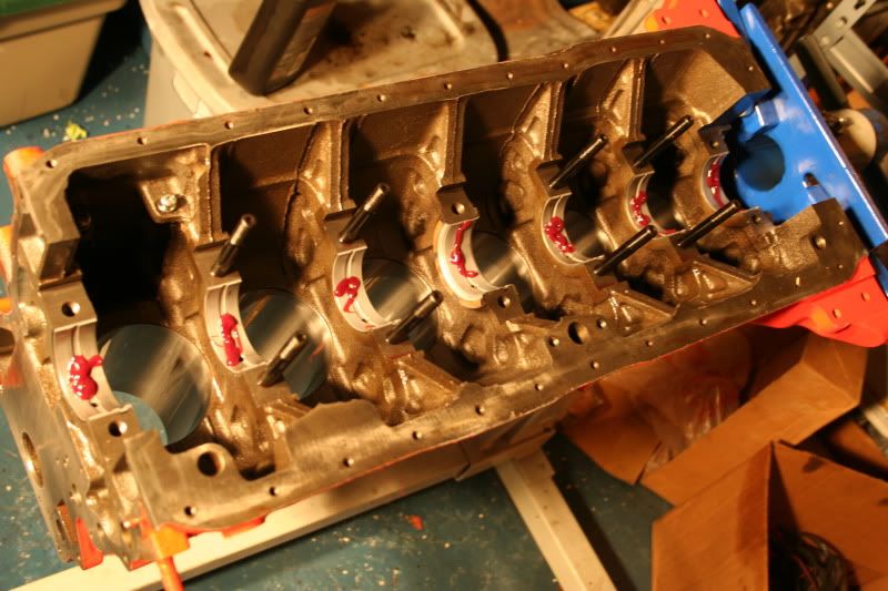
I didn't get much done today, but I did make progress. I've cleaned this block about 5 times now to make sure there's no contaminants or bits of metal and cloth.
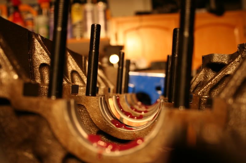
Clevite 77 main bearings are in. Plastigauged all the mains and everything is within specs. I hate removing and installing the main caps over and over again. The Datsun rebuild book I've been following says to wet everything with oil, but I figured I'd do it one step better. The Clevite engine assembly lube I'm using is the color and consistency of strawberry jam. Very thick, very sticky and gooey. It doesn't taste like strawberries though.
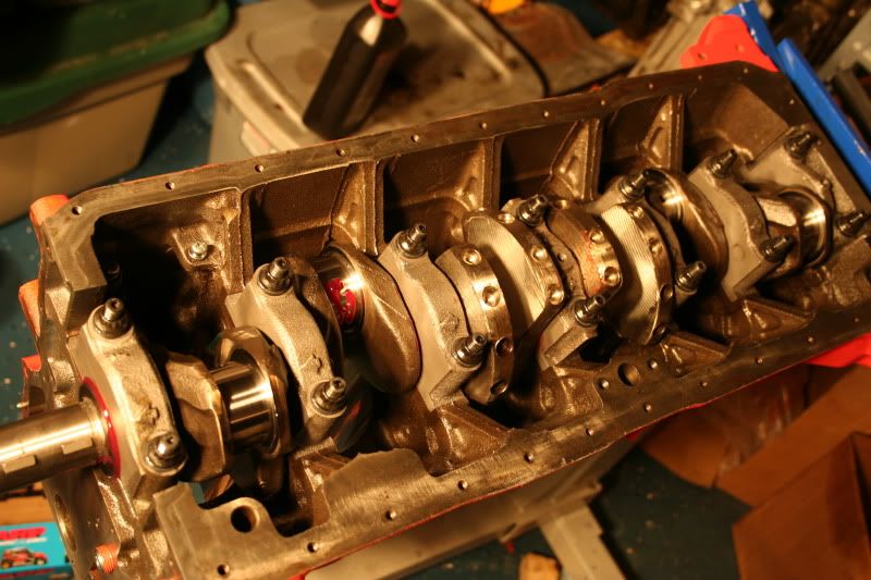
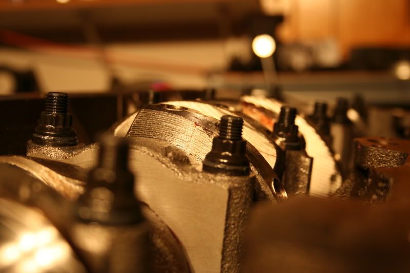
Dropping the crank in was nearly a panic attack scenario. Rear main seal was smeared with molybdenum and put on the crank first. After laying the bead of RTV in the groves of the rear main, I had to rush to get the crank into the block and torque it down... along with several other things in between. Its also really hard to do seeing as I can barely squeeze fingers between the back of the block and engine stand. Though that assembly lube is great, its so thick that I could barely tell if the crank was moving back and forth when I aligned the thrust faces of the bearings. After everything was cinched down to final torque the crank spins freely... as freely as one can imagine something spinning in a jar of fruit preserves.
Tomorrow if all goes well I'll be sizing the piston rings and installing the rest of the internal rotating assembly.
-
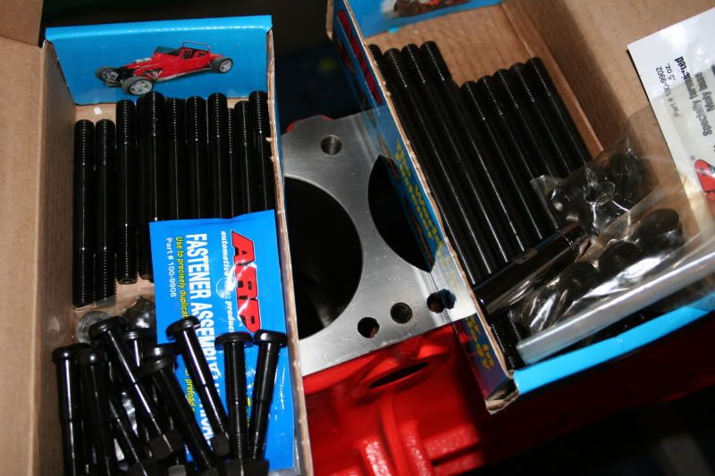
Very nice! My progress comes in the form of ARP head studs and a new timing set, and unfortunately that's it
Still need to buy a fuel cell and an AZC billet aluminum diff. mount and mustache bar for the R200Yeah, I hear you. This is only enough for me to complete the block. I still want/need to get fuel lines, big front brake kit, LSD, and do a bunch of welding among other things. Progress is still slow...
-
Play him off, keyboard cat.
-
BRRRRAAAAAAAAAAAAAAAAAAAAAIIINS!!
Seriously though, its not too hard, just time consuming. Label and disconnect your wire harness and other plumbing and test fit over and over to see if it fits and looks good. If it doesn't either deal with it and compromise for something a little less than ideal (but still functional and neat) or pony up and buy the needed parts to make it the way you want it. Just don't get so obsessed with hiding wires and lines that you forget to use proper isolation mounts and such, especially when it comes to SS braided lines and electrical wires. They tend to eat through each other when they touch for a long time, and the end result isn't pretty.
In a helicopter, an insulated electrical wire will "eat" through an adjacent hardline carrying 1500-3000psi of normally non-flammable hydraulic fluid. The end result is a red mist aerosol that will most certainly turn into a gigantic fireball when exposed to a source of ignition (like electrical generators or the wire itself). Think about that when running fuel lines especially.
-
I smell the smelly smell of impending progress....
... and a full set of new ARP hardware. The rod bolts and main studs had been held up in the midwest for quite some time.
-
Or you could go turbo KA24DE and have that torque and a smaller mid engine...
But yeah, an L6 will always sound better.
-
I'll preface this by saying that I don't have a 240z yet, just curious.
Always thought that when I pickup my Z I'll have a SR20 swap planned, and for one reason: weight distribution. For those of you autocrossing, what engine would you prefer? A turbo L28, or a SR20?
A lot of people will say SR20 for the reason you just stated.
-
The L28ET is a great "starter" motor to work on because of its simplicity and well, its already there in most cases. However, this is also its downfall. Because its simple and older, its not as efficient (i.e. combustion chamber design) and more difficult to extract higher power numbers. Good aftermarket parts are getting increasingly hard to find. This ends up being quite costly in a lot of cases. However in the power levels mentioned (250-300hp) it is pretty damn reliable and easy to work on and is enough to push an S30 chassis nicely.
I can't say whether it would be "cheaper" in the long run to extract higher hp numbers from an RB. It is more expensive in the initial investment, by far, than the L28ET or SBC. However you get a much more modern combustion chamber design, an extra cam, 12 extra valves, crossflow, and higher stock hp with greater potential. AND, you get to keep the awesome sound of a straight six. You will pay for the huge aftermarket support with an expensive JDM tax.
An American V8 will give you the greatest bang for your buck and will blow these previous options out of the water in that respect. High power numbers cost a fraction of what the Japanese motors will. I'm not a big fan of pushrods or externally balanced engines, but that's for you to decide. The sound of one of these motors under the hood of an S30 is a love/hate thing.
-
Okay then! So add crankshaft balancing. How much should that cost me? Anything else? Do I need the flywheel on it? Should I bring that to the shop?
Like I said, you don't NEED to attach the flywheel, just make sure its perfectly balanced itself. Balancing it with the crank is just a form of redundancy. Costs can vary, but my full rotating assembly balance probably cost the most out of anything else I did.
-
I thought these engine do not need to be balanced like I read in one of the stickies. Does it need to be balanced?
Balancing is ALWAYS a big thing for the rotating assembly. Its absolutely crucial. The key is that Nissan made a lot of these components very well so often when they're balanced at a machine shop 20-30 years later they're still within tolerances. However just because they're usually good doesn't mean you should just skip the process. The force a few mere grams of imbalance exerts is hundreds of pounds of force at higher RPM. It will severly reduce the life of the crank if not destroy it all together in very short order.
The L6 series engines are all internally balanced, so you don't "need" to balance it with the harmonic damper and flywheel installed as long as they themselves are perfectly in balance. I had them balanced, then also had them balanced again as installed on the crank just as a form of redundancy.
-
Looks good. Why did you do this instead of opting for the 2-1/16 gauges? I used that diameter and was able to install them in the stock housings as well. I used the front metal piece with the bar cut out as the mounting point for the gauge.
2 5/8" seem to "fill the holes out" a little better, plus I personally like the idea of a remote button rather than pushing directly on the gauge. Still, I wonder what it would be like to go with the smaller ones. Its annoying that they only offer the A/F ratio gauge in 2 1/16".
That's my two cents.


So you want to swap a ROTARY into your Z! (how-to)
in Other Engines
Posted
If someone ever crammed a 3 or 4 rotor setup into a Z... That would be pretty sick. Especially if it was a built NA.
Although personally I don't think the sound fits a Z as well, it still screams like a banshee!