baby_Carlton
-
Posts
58 -
Joined
-
Last visited
-
Days Won
9
Recent Profile Visitors
6951 profile views


baby_Carlton's Achievements
")


-

SLA S30 Front Suspension Conversion
baby_Carlton replied to baby_Carlton's topic in Brakes, Wheels, Suspension and Chassis
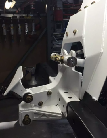
Yes, the front strut tower reinforcement is connected thru the firewall. Attached is a photo that kinda shows it off, these are slightly old pictures taken by the welder prior to taking delivery. Cage has since been finished and had gussets added to the A-pillars. The fender braces from Apex are located inside the front fender outside of the driver cabin. I also have them, not sure if I'll end up using them, cage installer wasn't convinced they really do much other than maybe preventing the front wheels from coming into the cabin during a head-on collision. Plinth location is the deciding factor in how your door bars and subsequent firewall > strut tower bars will/won't interfere with your pedal box. My door bars are pushing right to the outer edge of footwell and angle up from the bottom of the A pillar bar to fit my left if needed. Not sure what pedals you're using but I have a Tilton triple master setup that's going in so the world is my oyster so to speak in terms of pedal placement. This dude's pedal setup looks super neato and I would like to replicate the adjustment mechanism.
-
SLA S30 Front Suspension Conversion
baby_Carlton replied to baby_Carlton's topic in Brakes, Wheels, Suspension and Chassis
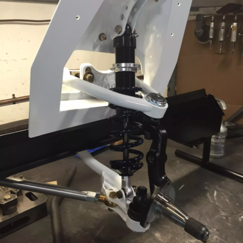
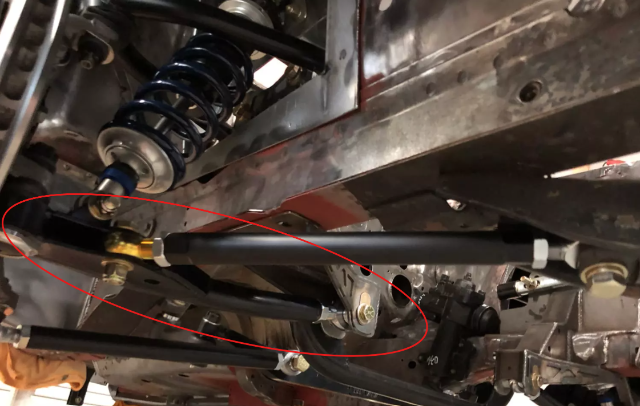
Unrelated update but reasons as to why there's been a lack of updates to this thread: Got a new job that demands a lot more of my time so unfortunately less time to optimize the SLA conversion. Upside however is that I'm learning NX which seems to be some next level software. I think this design is going to take one more fundamental change to really get the dynamic geometries perfect but the work I have so far has been a pretty excellent starting point. The car is also back from the rust repair shop and the cage shop, needless to say my wallet is in a lot of pain at the moment (especially with the S54 being built) but we do these things not because they are easy but because they are hard and we hate money. Anyway, enjoy some photos of the cage in the meantime.
-
SLA S30 Front Suspension Conversion
baby_Carlton replied to baby_Carlton's topic in Brakes, Wheels, Suspension and Chassis
Small update: Completed reverse engineering of the Cortex spindle, nice design and less tall than I anticipated. Unsure how I feel about the ~1.5-2" drop design but it will have to do for now until I can get everything articulating nice. Next step is designing a 17" wheel as it seems like all the models I'm getting off GrabCAD are not to spec. For the inboard UCA pickups, I'm at the point where I'm just trying to choose an angle for the UCA, the consensus is ~7° though I've seen some guys on the Locost forums go up to 10-15°. From my conversation with Maier, I remember him mentioning anywhere in the 15° range is too high for these kinds of cars. Anyway, back to the books for me.
-
SLA S30 Front Suspension Conversion
baby_Carlton replied to baby_Carlton's topic in Brakes, Wheels, Suspension and Chassis
Completely agreed and I am by no means a suspension expert. Following the fundamentals of suspension design is pretty straight forward when everything is static. Once parts start getting loaded up and components start moving around, things get a lot more tedious (which where I’m at right now). S54B32 shortblock, stripped head, and crankshaft with machine work done by Flying Colors Racing. Super happy with the quality of the work done here and I’ve always wanted to throw one of these in the Z. If it gets you driving the car more then more power to you. I don’t trust drivers in my area and the mountain roads are infested with double yellow-crossing IS250 drivers and morons in daddys Audi flying off cliffs. For a fun street car I want airbags and actual crumple zones so I’m trading the street for a controlled envrionment. -
SLA S30 Front Suspension Conversion
baby_Carlton replied to baby_Carlton's topic in Brakes, Wheels, Suspension and Chassis
Update: after speaking to Cortex and getting some spindle dimensions from them for CAD mockup, looks like I’ll be using their Radial X spindles. Very exciting stuff, I am a bit weary about using aluminum spindles but the car is a track car and last weighed at ~600# over each front wheel so I think I’ll be alright. Thanks! Excited to share my progress with you guys. I’d eventually like to make my work/design open source and see what more talented suspension engineers can do with it. If I didn’t just buy one of these yesterday I’d offer to trade you a complete kit for one of them KN20 heads XD. A bummer indeed, just another bump in the road! Funny you mention Stock Car blade-swaybars. It’s basically all I’ve been looking at for switching over to that design. Plus the parts are pretty cheap & standardized. Thanks everyone.
-
Not dumb at all, though I definitely prefer rubber bushings over poly & solid in a street car even if its tracked 1-3 times/year.
-
Small update, I've moved to a new thread on designing my own front SLA suspension. Regarding the OTS kit from AE, its nice, the tubular front cross member is perhaps the best of its kind on the market. Part of me wishes they used slot-nuts instead of their current configuration but its not a huge deal. Interesting, sorry to hear. I find their rear suspension pretty well designed, the rocker ratio is 1:1 which is not great but nothing you can't fix by making your own. Though for $4000, I feel it should've been disclosed at the very least. Their new packaging system for hardware is great, though their shipping packaging is quite bad. Their customer support offered to replace some parts that were damaged in shipping, need to follow up to check what the ETA on those RMA'd part is. Regards to you giving them feedback, not surprising. I've also tried starting a technical discussion with them that they didn't seem super interested in, understandable they're running a business and are more concerned with keeping the doors open than answering questions from a guy that already paid them lol. These guys are developing kits for a bunch of Datsun/NIssan chassis, and now the E36 chassis so I doubt they have a lot of time for guys like us.
-
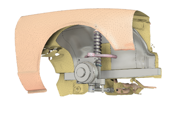
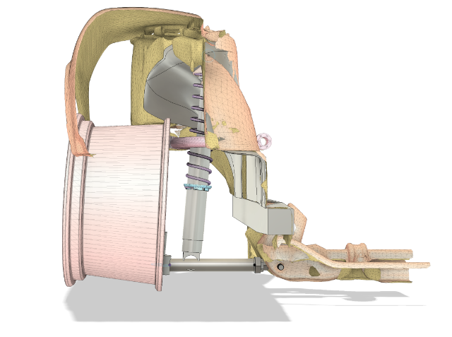
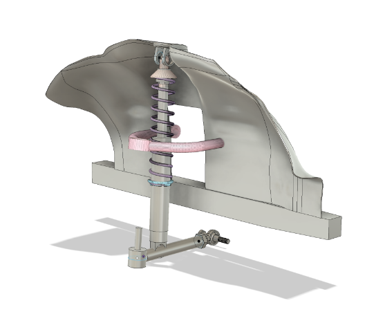
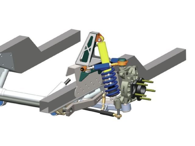
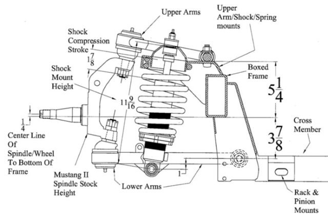
Hi HybridZ, Some of you have already seen my Apex Engineered Track Attack information/discussion thread here, I've decided after reviewing the design of the Apex Engineered front suspension kit, the best solution moving forward is to design my own. In this thread I will be documenting my progress and hopefully gaining knowledge on suspension design from you guys (or from what's left, f**k Facebook groups). To start... Why don't you just use the AE kit? It was $4000, you're just gonna waste $4000??? (Yes) Not enough shock travel, that's pretty much it. Once I received the shocks from Viking I realized immediately that 3.20" of stroke was not going to be enough and thus set out on a fool's errand to find alternative solutions. Viking shocks, from what I've found, have the most shock travel per the physical dimensions of the shock that I've seen so far. They're compact and the adjustment knob is well-designed to take the least amount of space with respect to the rest of the shock body. Very nice, but I will ultimately use either JRi's Mod series DA shocks or Penske's 7800/8300 series DA shocks as now, getting a shock long enough to reach between the strut tower and the LCA is more important. Design (pictured with 17" diameter wheel) The most prominent feature of my SLA design is the UCA pickup being located within the engine bay. The shock tower must be cut and a box structure is welded to the frame rail. This design is based on both the Maier Mod 2 design and Cortex Racing SLA kit seen here: Maier SLA Design Cortex SLA Design The reason I moved the chassis pickup for the UCA inboard was to extend the length of the control arm which should allow for a more compliant spring than the offerings from Apex. Mike Maier inferred the reason for the obscenely high rates was to keep the super short UCA from camming over and ruining the geometry. Fine for a super stiff autocross car but for a road-course car with kerbs, burms, and undulations in the track surface? Unacceptable. With this shock, I'll be looking at around 7-8" of total shock stroke travel. The remaining part of the design lies with the spindle (not shown) and the boxed-structure (also not shown). The boxed-structure was fairly straightforward to design - shout out to @Ben280 for sending me frame rail measurements while my car's been at the body shop. The boxed structure welds to the chassis frame rail located in the engine bay which the cross-shafts then mount to. The spindle is obviously not straight forward, fortunately for me there's plenty of resources on the LocostUSA forums for me to look at as well as Chassis Design and Race Car Vehicle Dynamics by Milliken and Milliken. Once the completed version 1 of the design is done, I’ll begin FEA with a safety factor of 1.15-2.00 at some lateral load to make sure everything should work without buckling. Until then, I have two separate designs, one utilizing Mustang II style cross-shaft mounting structures and one using Maier’s. The main difference being the orientation of the cross-shaft mounting bolts to the boxed-structure with the Mustang II’s bolts facing down, and Maier’s facing sideways. With the bolts facing sideways relative to the longitudinal axis of the chassis, side load is transmitted into the boxed structure through the bolts on their axial axis as opposed to their shear axis. Bolts do not like shear, however the Mustang II design is insanely popular so I suppose I could be overthinking this. Maier Cross Shaft Mounting Design Cortex/Mustang II Cross Shaft Mounting Design Methodology Starting with a 3D scan of the 240z that I re-topologized into ~10000 quads, I modeled an accurate-enough solid body of the fender well and shock tower. From there, I (roughly) modeled the Apex Engineered LCA (will probably try to use the T3 ones I currently have installed on the car as they are boxed structures), the Penske 8300 coilover at ride height, and upper control arm. You may have noticed the bottom of the shock clipping into the LCA, please ignore that, you didn't see that. In regards to swaybars, I will try to get the OEM sway bar design to work with my suspension, however due to the bottom of the shock being mounted on the LCA roughly where the swaybar links, this may be difficult to engineer. I could copy Maier’s LCA design, using a bent-tubular lower arm picture here: Moving forward, it might be easier to design my own boxed structure and try to mount a blade-style sway bar instead. Procurement While there's going to be a lot of custom laser cut metal from SendCutSend, I wanted to keep this kit as OTS as possible. I am not particularly interested in spending buku-bucks on one-off billet parts nor am I keen on dipping my feet into scaled automotive aftermarket product design & manufacturing. That being said, the spindles will likely need to be entirely custom if I can't find an alternative OTS. If I can find an upright on the market that fits my criteria I will definitely go for that, I’m trying to avoid using a Mustang 2 spindle as its shorter than I’d like it to be and completely wastes my steering knuckles and 370z spindles supplied from Apex Engineered (though steering knuckles and spindles are relatively cheap). Next Steps The complete version 1 of this design will be complete soon. Once I've finished my spindle and boxed structures the real work starts, articulating the design through all of its axes of rotation and movement will reveal conditions of binding and the dynamic geometries of the suspension. I started work on this project about a week or two after I placed my order for Apex Engineered SLA kit and have been doing it in my free time which is quite difficult to come by. God willing I shall endure.
-
The reason for replacing them is not for quality, its for fitment. I'm pretty sure Viking offers a coilover long enough to fit with my SLA design but I know the Penske one will work. I just need to check for interference in the UCA throughout travel. Lol well if you wanna save a few pennies on the front kit from AE let me know, I'm going to get rid of mine. That last part is probably true, but more tie rod ends means more maintenance and more failure modes. Dirt and debris entering the ball joint and load fatigue both contribute to this. I've spoke to Viking and they were very helpful. A little confused on the choice to use the C203 shock with the motion ratios given to me by Apex. From their reaction and the assessments from Rob Fuller and Mike Maier I'm standing by my opinion that 3.2" of shock travel is simply not enough.
-
I see, it seems AE just sent me 4 identical C203 shocks from Viking and said have at it. I won't be using them anyway, the entire front suspension kit is pretty much a wash for me at this point. Going to just resell it for cheap once I finish my own design. I'll be either using JRi modular shocks that are 21.7" extended or Penske 24.7" extended. I agree, there's too much usage of many tie rod ends, from an engineering perspective it just adds more and more failure modes, more and more maintenance. I'll edit this post and link my front SLA thread.
-
I just received the kit on Friday, the front kit will likely stay uninstalled. Not sure what you mean by "asking hypothetically", I'm designing a new front SLA suspension that will allow a full length coilover to mount to the LCA.
-
I'll take the scan if you still got it, appreciate you doing this. I have a scanner at work but its difficult to justify bringing home a $50k+ piece of equipment for the weekend XD
-
I agree, I reached out to Apex earlier this week asking about feasibility using the existing shock stroke with 400-450# springs. Yes, loading the outside tire on burm and then hitting an imperfection on the track seems like it would decimate one of these shocks (same with hitting kerbs/rumble strips) unless I find a way to get more travel. If I could get 5inches of travel I would be very happy but I will try for a full length (~6.5") shock design if I end up copying MMI's Mod 2. Very interesting, would definitely prefer welded to bolt-on but if everything fits up right I could end up using it as a way to test different upper wishbone lengths. The Griggs conversion looks like a pretty strong structure but I don't want to jump to conclusions quite yet. Do you have any photos of your work? Interested to see what your mounting solution looks like. If I can avoid trimming the strut tower and still get the full stroke shock I will.
-
Tire selection is Nankang CRS 200TW 245/40R17 front, 275/35R17 rear, I would use their AR-1 100TW however they do not offer a 275 section tire for that model. Car will be almost exclusively a track car but despite my spine's best interests it'll probably see a very occasional Sunday drive. Were these rates with OEM-style strut type suspension? What were your wheel rates? Maier's issue with the shock travel was that unlike an autoX/hillclimb car, a road course car would see burms and 3.5" total shock stroke just isn't enough. Great insight still, thank you. The kit just shipped about 3 hours ago (for better or for worse), when it arrives I'll be able to get those measurements to see. When you say "adequate travel" I'm assuming a that refers to just enough travel for the ~3 inches of travel you've needed for your own car? I'm assuming if I want something closer to 5-6" travel, the upper arms would need to be closer to a foot long. That's what I'm finding as well just looking at Maier's Mod 2 front axle suspension kit. Complete replacement of the front strut towers moving the pickup points slightly upward and a few inches inward to increase clearance between the coilover and upper control arm. I'm not opposed to doing this and I could even keep most of the Apex kit except for probably both the wishbones. Ah yes, old stockcar components on eBay, a true goldmine for (hopefully) decent parts. Definitely have looked at sourcing a fuel cell and oil coolers from there. Luckily I have access to rapid prototyping equipment and fabrication tools so I'm good to go. Not the best welder or anything but I know a few. Thanks for your help tube80z. Only other gripe I have with this design is on the rear subframe; the differential and control arms mount on the same structure and that seems like an exceptionally suboptimal design choice. Time will tell I suppose.
-
Spoke to Mike Maier today seeing as the front suspension is most similar to that of an old Mustang. I wish I could write notes faster because holy hell that man is a wealth of knowledge. Suggested the reason for high spring rates is to prevent the upper control arm from camming over (poor arm design) and that the 3.5" of travel is definitely not enough for a road racing/track car (burms). Looks like my next steps are installing an adjustable upper ball joint that can move up/down to change the coilover angle and shock pot it at ride height looking for the lowest load value. If no substantial gains can be made there it's either back to the drawing board to make a push/pull rod cantilever or cut out the shock towers entirely and try to copy MMI's own Mod 2 strut tower modifications as well as new control arm(s) to gain the ability to mount a full length shock to the lower wishbone. This is becoming more and more of a fully custom project by the day.