nicksoccer22
Donating Members-
Posts
23 -
Joined
-
Last visited
-
Days Won
4
nicksoccer22 last won the day on October 22 2024
nicksoccer22 had the most liked content!
Contact Methods
-
Website URL
N/A
Profile Information
-
Location
Minnesota
Recent Profile Visitors
4851 profile views
nicksoccer22's Achievements
-
Wiring help for hazard switch
nicksoccer22 replied to robotbbq's topic in S30 Series - 240z, 260z, 280z
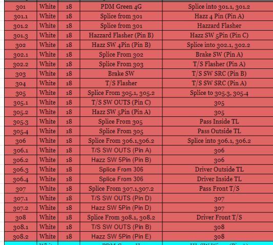
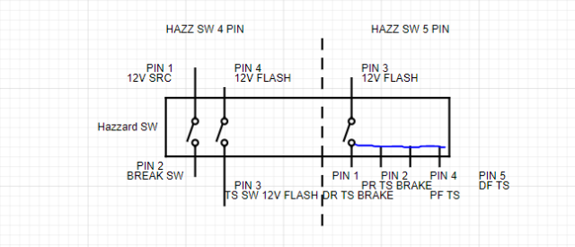
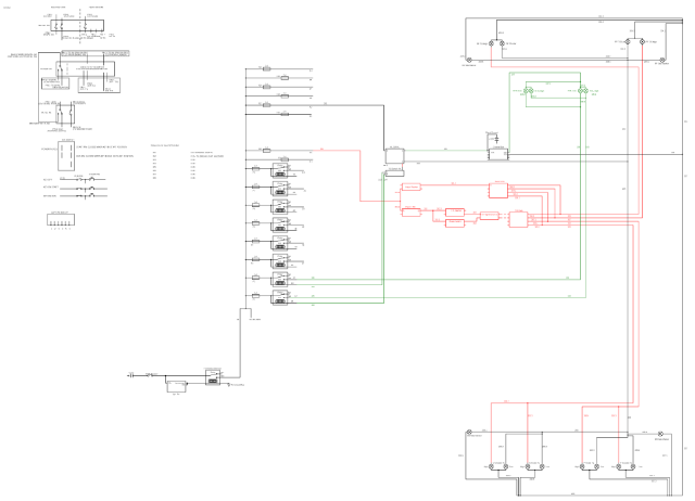
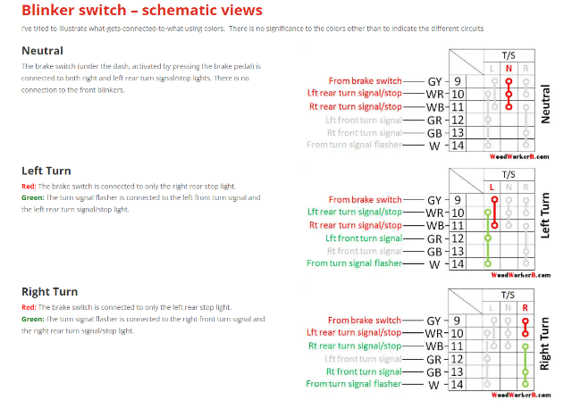
A few notes before I get into it 1.I am rewiring my car from scratch. So I have no clue what color wires correspond to what pins, or what year switches I am using 70-78 2. I'm not using the stock taillights, I only have an off, high and low signal, all red(Think Semi trailer lights). So the way I wired stuff might be different for you 3.I feel that if you understand the concept of what I am showing below you can adapt what you have to create something similar. I am an idiot when it comes to wiring, but I got this to work for me so feel free to copy it at your own risk haha. This definitely isn't stock Hazard switch (Ignore the PinX stuff for now, That is how I am keeping track of what wire is going to what pin on the connectors I have) I see the hazard switch as the first step in how the power is routed. The switch has two different states (Noted by the vertical dashed line in the image above), on and off, each with it's own outcome. Hazards on: (Right side of above image) 5 Pins should be connected on the switch when the hazard switch is on/closed, use a multimeter to test continuity between all the pins, and note which ones are connected. One of the pins should receive 12v + from a flasher unit (I am using a PDM (Bussman31s002) to get fused 12v power, then putting that into a 3 wire flasher unit that is adjustable to set the timing of the flashes). So when I have my hazard switch on, power flows through the pdm, then into the flasher, into one of the 5 connected pins on the Haz SW, then a wire out to each of the 4 turn signal lights. This also kills all connections to the "Off" side of the switch. In my case, this disables the turn signals, and brake lights. Hazards off: (left side of above image) there are going to be two sets of two pins that are connected when the hazards are off/closed. Use a multimeter, check continuity, write it down. Feed one of the pairs with fused 12v+. The pin that is connected to the 12v+ gets a wire that is spliced into 2 different locations. Location 1 is the brake switch. Location 2 is a second Flasher unit. These two wires then come back together to feed the Turn signal switch, one flashing, one constant. When the switch is in this position, everything on the right side of the above image is no longer connected. Turn Signal Switch The Turn Signal Switch works off of two inputs 12v constant (Connected to 2 pins that should correspond with your Brake lights, and will disconnect from one of the pins if the turn signals are on in that direction) and 12v flashing (Connected to either the front left and rear left, front right and rear right pins, or no pins at all depending on the location of the stalk. So, for me, If my brakes are on, I get a signal to the "high" side of my tail light. WoodworkerB's website is invaluable. I recreated all of his diagrams with the corresponding wire color of my switch to use for my own project. https://woodworkerb.com/home/datsun-240z-rebuild/blinker-detail/ https://woodworkerb.com/home/datsun-240z-rebuild/datsun-240z-multifunction-switches/ Below I have a schematic of what the whole thing looks like, minus the detail of what the internals of the switches are actually doing, as well as the pinouts. (right most column is where the wire terminates, to its left is where it starts) Looks like the images are tough to read. DM me if you want a full size copy. Let me know if you have questions, or tell me that I'm wrong haha, The harness still in the basement so I would rather fix stuff now than when it is in the car. But as is the lighting system is functional, I pulled out a bunch of stuff to test it all. -
TrackZpeeds CXRacing LS1 T56 240z
nicksoccer22 replied to trackzpeed's topic in Gen III & IV Chevy V8Z Tech Board
Carbon Signal Moonbeam -
I do plan doing a heater/defroster, but figuring that out is a problem for future me haha. From what I have seen a lot of aftermarket kits are pretty narrow, and I don't think it will be a problem. As it stands I can move the assembly away from the firewall ~3" without the door of the PDM hitting where the heater controls would go, I can also change up the angle so it sits more vertically, If I do that I could probably run the stock unit, but I really haven't done a lot of digging on that.
-
Any chance you'd be willing to post some pictures of with the mirrors installed, and if you have any the plate you made to attach them?
-
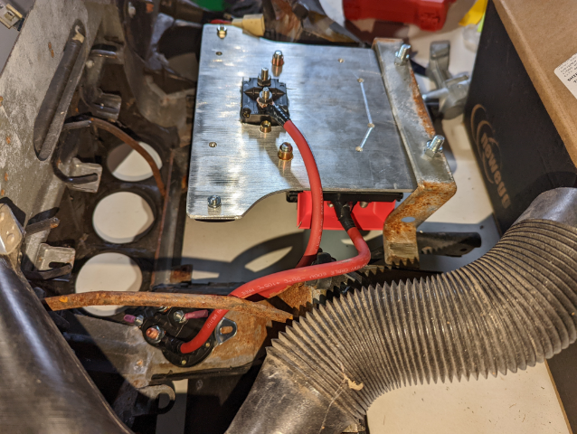
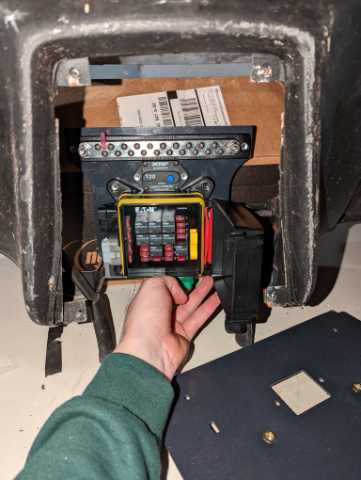
I'm not using a painless kit, and I am not planning on using the stock heater components/panel, so this might not be the most applicable, but the images below are what I am doing to mount a Eaton Bussman 31M series PDM and some other components for wiring. Front view, Drilled a couple holes into the inner/lower dash support bar and added rivnuts. I also have a connector piece not pictured that connects the top of the plate I am mounting everything to with the underside/top of the dash for more stability. View of the back, no rivnuts yet in this pic, and an earlier version of the mounting plate but you get the idea. I have been doing all the wiring with a spare dash outside of the car, along with my good dash in the car, it is really nice to reference points on the dashes to determine the length of wire I need to get to places, and not have to worry about pulling it all apart to wrap it later.
-
+1 on Merch. Trucker hats would be sweet.
-
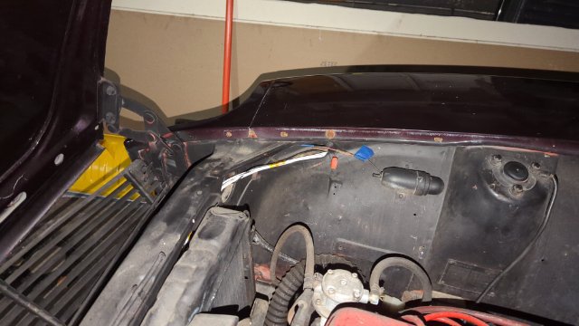
Hey fusion, I'm also rewiring my car and saw your post and decided to try something like it. I removed the fresh air vent thing on the passenger side. From there I ran a fiberglass wire snake through and it ended up coming out right in front of the inspection light. I don't have pics of the interior side of what I did but that should be pretty self explanatory. I'm using Delphi/ aptiv metri-pack 280 series connectors, and when I was testing things out I was able to fit a 5 pin connector through the cavity, but it took some doing. I ended up only needing a bunch of 3 and 2 pin connector, so routing them wasn't too difficult, but I was careful to stagger the connectors off the main loom, and used plenty of tape to get it to all fish through. Overall it looks pretty nice, still need to sleeve it all and figure out grommets. Imo it's worth the time if you are rewiring. Doesn't take much more time, cleans up the engine bay and is probably a more reliable set up than having them sit on the frame rail
-
nicksoccer22 started following 480Z - cheap 2+2 build and Round Tail Lights
-
My 240 was rear ended in a past life and the previous owner had it fixed in an interesting way. Instead of the inset taillight panels and stock lights it has sheet metal attached flush to the rest of the panels so the back looks very flat, He also had 4 cheapo round (I think 5" diameter, but I forgot to double check that and I'm at work now, I'll update it when I get home) brake lights with no other functionality. The PO ruined the wiring, and when I was driving it to storage before going to college it started on fire under the dash and I haven't touched it since. So I am planning a new harness using a Eaton Bussman 31S-002-0 and I would like to actually have functional turn signals/running lights/reverse lights, So I am looking for new round tail lights. The things most important to me are Using 4 lights (2 per side obviously) have a red brake light, red running light, amber turn signal, and a white reverse light I would really prefer Non-led, but I I doubt that will be possible with my next point Mount as flush/ tight to the current sheet metal as possible. I wanted to see what the stock tail lights looked like on my car and just held them up to the hole the current lights are mounted and it looked VERY silly sticking out so far. so a flush mount is ideal. I am willing to cut the holes larger, again I will check to see what they are currently. Would love for the "lens" the lights to sit behind to be either all red or all black/smoke in color. Does anybody have experience using aftermarket round tail lights and have suggestions on brands? I don't mind spending some money to make sure I get what I want and not have to worry much about them dying quickly. The closest I have found can be found on ebay by searching "Euro Red Amber LED Combo Multi-Function Round Stop Turn Brake Tail Lights", It's the one for $90. The only thing I don't like about these is I don't like the look of the lenses with the multi color thing going on. Has anybody put a film tint on something like this? I thought that could be a work around for the issue I thought I had a better picture somewhere but I guess not.
-
From the sounds of it the guys at industry garage are thinking of making carbon fenders, Check them out on YouTube. I doubt they'd be the stock shape though
-
Retro-spec
-
Found some cool old videos on youtube of some racing story of the top competitors, Jim Fitzgerald, Paul Newman, Frank Leary, and Logan Blackburn for the 1978 SCCA championship at Road Atlanta. Not all Z related, but if you want to skip to about 9:40 in the video you get some datsun stuff. at 10:47 you can see Bob Sharp blow a tire and roll the car after hitting a barrier.
-
I'm looking to learn about how to read wiring diagrams and just understand the wiring of Z's better. Anybody have some suggestions on books/ videos That work well for that? Looking at either the diagrams or the actual car has me beyond confused and instead of asking a bunch of beginner questions here I thought it would be better to learn something for myself. Thanks guys!
-
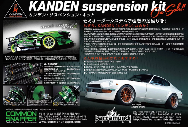
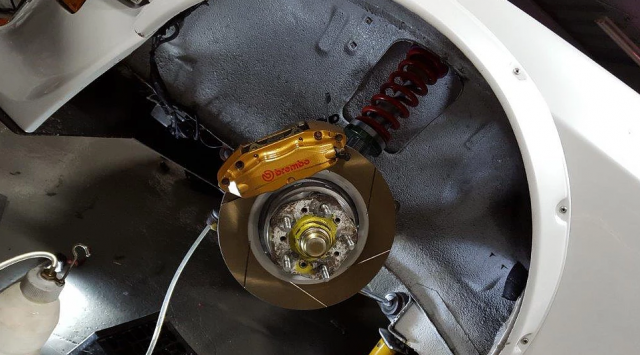
Well, I fell in love with the white Common Snapper Z car, and after looking through the gallery tab in their website I saw a picture of the white Z with 5 lug hubs and Brembo's. The picture has a label under it that says z33 caliper and rotor. Does anybody know if they sell a kit for a brake/hub swap? I haven't seen much on these guys on the forum, and a lot of the info I have found about them leads to dead links. They also have some really nice looking Coilovers, but they are very expensive. Anybody from the states work with them before? How was shipping times and prices? How was customer service? Thanks guys, Nick
- 2 replies
-
- common snapper
- coilovers
-
(and 2 more)
Tagged with:
-
480Z - cheap 2+2 build
nicksoccer22 replied to northwoodz's topic in Gen III & IV Chevy V8Z Tech Board
I've been looking into the Japan racing wheels as well, are you going with the 8 spoke style? When they come in I'd appreciate it if you commented on the quality of the finish and your initial impressions. They have two bolt patterns cut into them, I don't want to derail your thread, but have you or anybody in the community heard of that making the wheels less durable? Thanks, Nick -
This is definitely not for everybody, but a very cool build in progress with lots of carbon fiber.


.png.00ba7668e3b86ef19d6564579d3fca92.png)
