MECH-E
-
Posts
19 -
Joined
-
Last visited
Content Type
Profiles
Forums
Blogs
Events
Gallery
Downloads
Store
Everything posted by MECH-E
-
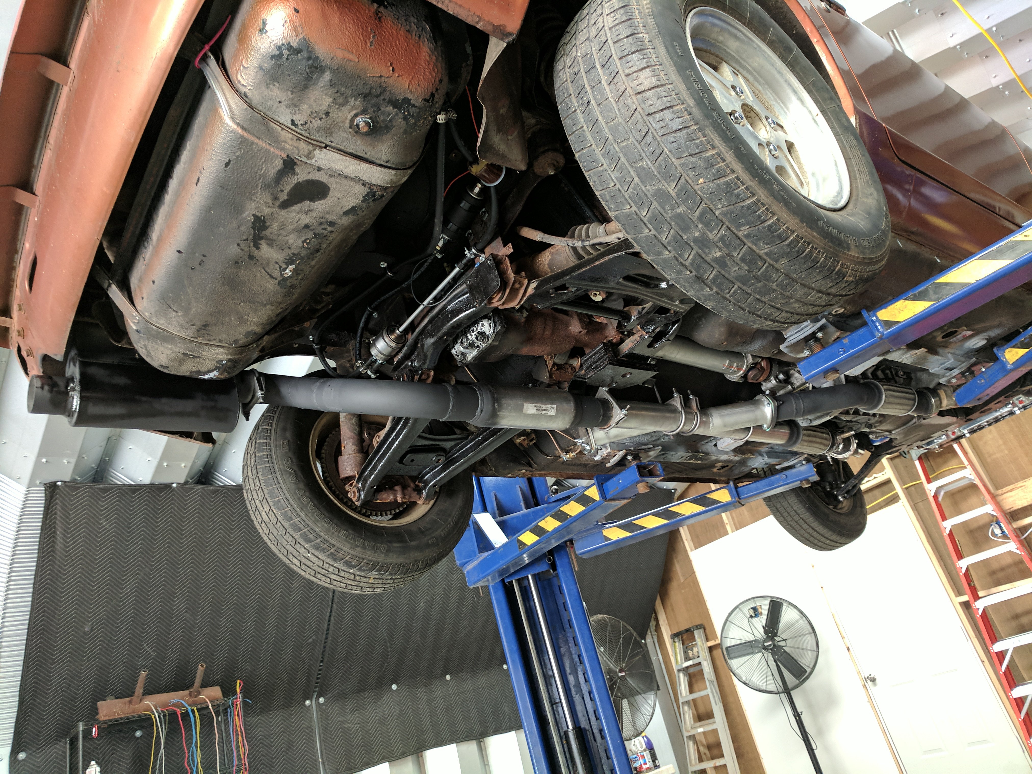
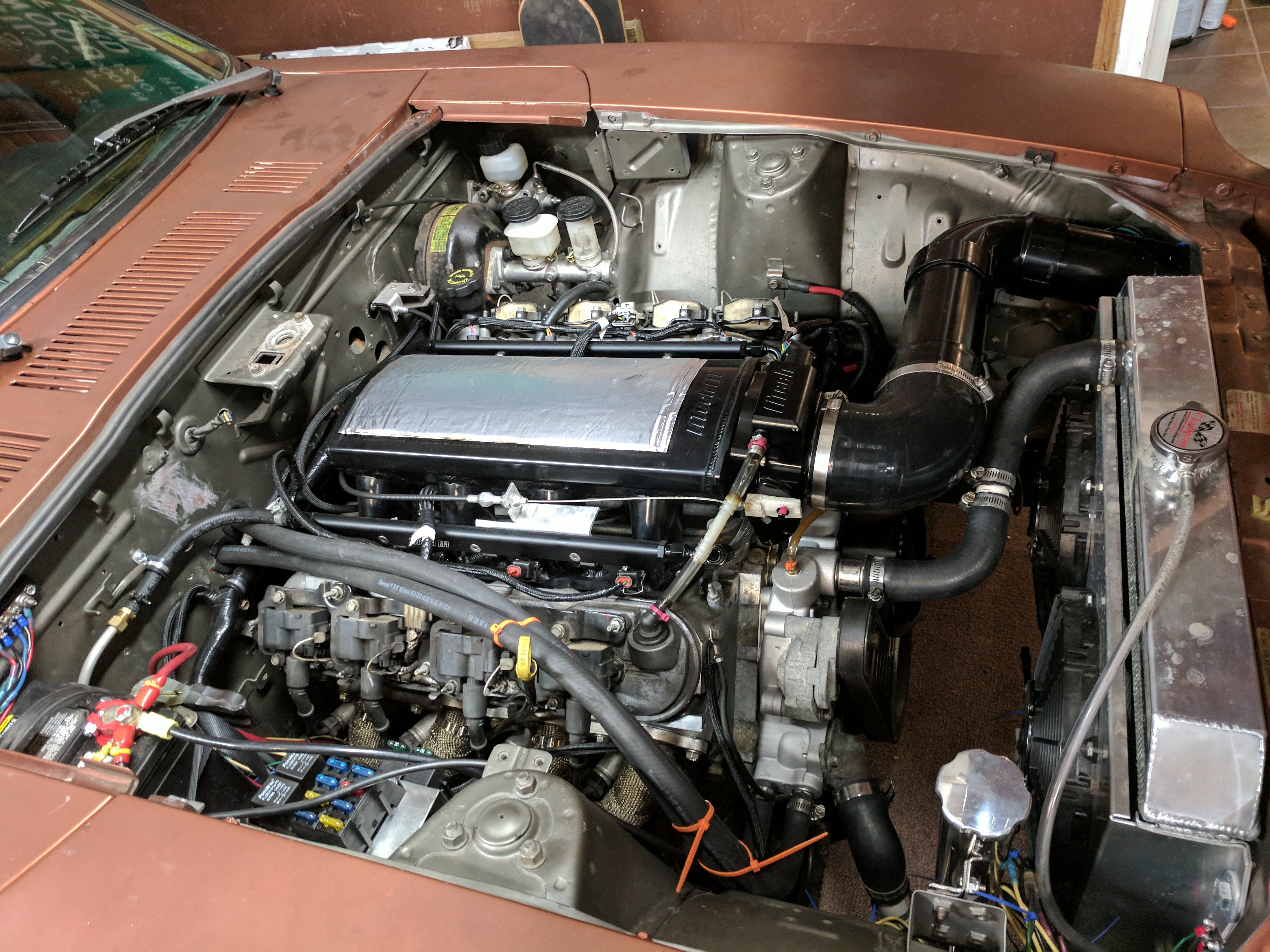
1977 280z Donor Car 1999 Camaro LS1 T56 Hawks Weld-in Engine and Trans Mounts Stock Block and Heads CX Racing Longtubes with a lot of time beating , banging, cutting, welding to make fit 3" Header collectors to Y Pipe to single 3" out the back Hawks Sinister Cam Kit (cam, springs, retainers, pushrods) Fitech LS Ultimate Kit Including: Aluminum Intake, Fuel Rails, Injectors, Throttle Body, Sensors, and obviously the computer and wiring Champion 2 Core Radiator w/ Spal Fans Shortened Camaro Aluminum Driveshaft, JTR Pinion Flange adapter for 3130 U joint on the rear Stock R180 Diff, welded (yeah I know...its gonna blow someday) Puny 215 tires, mostly to save the diff. The tires in the pick have been replaced, Im not drag racing on dry rotted carcasses of a tire lol Best 8th so far is 8.2 at 91mph with a soft launch to save the rear ~2.0 60ft. 8th Mile

-
Do you have access to a welder? That can determine a lot as well. I used the Hawks engine and trans mounts. I like the engine mount, not a fan of the trans mount. But both require significant welding so keep that in mind. Also header fitment became a huge issue, took me months of modifying headers to finally fit. Going with shorties might of made it easier. I haven't looked into any of the more recent kits, but if I had to do it all again I don't think I'd go with Hawks. Maybe just the engine mount, but even still it would require significant header massaging.
-
 So im nearing completion of my ls swap and started looking into gauges. Found that there aren't a lot of options and whats out there is expensive. So I'm making the stock gauges work by gutting them and modifying them heavily to work with the ls stuff. As far as cost goes, this should only cost me like 50 bucks for the gauges themselves, the senders I'm leaving out of that number. Here is a simple overview. The speedometer, oil pressure, coolant temp, and fuel level will all be driven by an arduino controlling 4 separate servo motors. If you don't know what an arduino is, google it. The way this works is, I will install a servo motor behind each gauge face. The servo is controlled by the arduino, which receives inputs from the senders or my ECU (in this case I am using Fitech for the tach and speedo, the rest are separate senders). Most aftermarket senders operate on a 5V reference, usually 0.5V being 0 and 4.5V being max (aka 100psi or 250F...whatever). An arduino can take these inputs and then control the servo motors to move to a position that represents these values on the gauge. I haven't finished the setup, but here are some videos to show the motors moving through their range. For now, the servos im using only move 180 degrees, so the speedo will only go to 110 mph, but who even looks at the speedo after 100mph anyway. This is literally just me holding the servo behind the gauge face for now....and yes, that is a pink zip tie with pink heat shrink acting as my gauge needle....super classy haha. Speedo Fuel level
 -
Ls1 to Champion radiator hoses.
MECH-E replied to jlangv2's topic in Gen III & IV Chevy V8Z Tech Board
Nice setup. I personally planned on running one of those thermostat housings from jegs that is a straight input to the water pump from the radiator. That way, you dont have to deal with the weird angle of the stock water pump inlet and they are the same diameter. Jegs Part # : 53270K http://www.jegs.com/i/JEGS-Performance-Products/555/53270K/10002/-1 But hey, nice to know the parts needed to use the stock neck. While I'm here, are you using the stock steam port tubing and if so where are you planning to plumb it in? -
Cam kit (cam, springs, pushrods), oil pump, timing chain, and new gaskets and you'll happily have a stout ~350whp that should run forever. If you're not doing a cam, I'd just do gaskets and go. The LQ4 in my truck has 312K miles and I bet it's got the stock oil pump and timing chain. If you're leaving the stock cam in there, the stock stuff should be fine. Something I did just replace was the oil pump pickup tube O-ring. It was causing low oil pressure and a ticking lifter. It's easy to replace with the pan off and costs all of $2.
-
Hawks Motor & Trans Mounts - Install with Pics!
MECH-E replied to MECH-E's topic in Gen III & IV Chevy V8Z Tech Board
^ Looks a lot better than mine. Sorry guys, will try and get pics up, eventually -
Hawks Motor & Trans Mounts - Install with Pics!
MECH-E replied to MECH-E's topic in Gen III & IV Chevy V8Z Tech Board
It welds to the floor of the car, wasnt quite close enought to weld to the frame rails. Getting the floor to have the same shape as the mount proved to be a huge pita. So I cut out the floor, welded a big plate to the top of the mounts, and then welded the plate back to the floor. In all, its massively over designed for the loads that the trans experiences. All the other mounts out there, even the simple JCI kit, are bolt in and I've never heard of one failing. Too late, already welded everything in. Will hopefully get around to test fitting those headers in the next few weeks. Right now, they are the sexiest paper weights I've ever had lol. -
Hawks Motor & Trans Mounts - Install with Pics!
MECH-E replied to MECH-E's topic in Gen III & IV Chevy V8Z Tech Board
I just finished it this past weekend, will get picks up soon. Just a heads up, I'm not a big fan of it. -
Hawks Motor & Trans Mounts - Install with Pics!
MECH-E replied to MECH-E's topic in Gen III & IV Chevy V8Z Tech Board
Gotcha, makes sense. Thanks BTW, I moved that steering rack clamp to the passenger side, looks to work perfectly there. Here are a few shots to show the clearance of the motor between the crossmember, its close but with it all resting on the mounts like its supposed to, I have nothing rubbing. And heres a reference for how far the oil pan sits below the crossmember. Perspective throws the measurement off a bit, its likely 2". -
Hawks Motor & Trans Mounts - Install with Pics!
MECH-E replied to MECH-E's topic in Gen III & IV Chevy V8Z Tech Board
I tried putting them on with the engine in the bay, doesnt seem possible. I have to pull the engine again anyway, gonna try bolting them on and lowering the motor in assembled. -
I love the ease and simplicity of FiTech units....not to mention they are significantly cheaper than the competition. After doing 2 megasquirt builds, I'll be going FiTech for anything EFI N/A and seriously considering them for boosted applications as well.
-
Hawks Motor & Trans Mounts - Install with Pics!
MECH-E replied to MECH-E's topic in Gen III & IV Chevy V8Z Tech Board
Hmm...think the rack would be fine if I welded that bracket to the rack and removed the u-bolt...just a few good tacks, shouldnt need a whole bead of weld? The bracket doesnt appear to get in the way, just the u-bolt....currently at least. As for the oil pan, it does stick out below the cross member, I assume a lot of people replace the oil pan with a shallower version if they think it is a big deal. I might try to make some sort of skid plate to protect from road debris, but I sure hope I never land it on a curb or speed bump. -
Hawks Motor & Trans Mounts - Install with Pics!
MECH-E replied to MECH-E's topic in Gen III & IV Chevy V8Z Tech Board
If you look at this picture, you see what looks like an exhaust C-Clamp? I have no idea why its there but my oil pan is actually resting on that. I didn't realize it until I was closing up. So I dont know how low it will sit once I remove that clamp. I'll update the first post once its gone. -
Hawks Motor & Trans Mounts - Install with Pics!
MECH-E replied to MECH-E's topic in Gen III & IV Chevy V8Z Tech Board
Updated the post with the mounts on the motor. Will hopefully finish the trans mount next weekend. -
Hawks Motor & Trans Mounts - Install with Pics!
MECH-E replied to MECH-E's topic in Gen III & IV Chevy V8Z Tech Board
Dang, those CX headers look pretty darn legit....and less than half the price of Hawks headers. Heck, they arent even much more expensive than the JTR/Sanderson shorties. This might actually be what goes on my car! -
Hawks Motor & Trans Mounts - Install with Pics!
MECH-E replied to MECH-E's topic in Gen III & IV Chevy V8Z Tech Board
Pretty sure all of them fit, I'll be ordering JTR headers when the time comes. I initially thought only Hawks' headers would fit, which are $1200 ouch. After talking to a few people that have run them, I know JTR will fit and I dont see any reason that any others wouldnt. -
Hawks Motor & Trans Mounts - Install with Pics!
MECH-E replied to MECH-E's topic in Gen III & IV Chevy V8Z Tech Board
Yes LS motors, I'm doing a 99' LS1 T56 -
Hawks Motor & Trans Mounts - Install with Pics!
MECH-E replied to MECH-E's topic in Gen III & IV Chevy V8Z Tech Board
Reserved for Trans Mount -
I've never seen a thread where someone documented how hawks mounts actually mount up and are installed. So I took a bunch of pics when I did mine for all to enjoy. Chassis Mounts Here's how the mounts look in your hand. I'll explain what each location really does as we move along. And here is the back of the plate that you must weld onto the frame. As you can see, you must clearance the frame in order for the plate to site flush again your frame rails. But before we get into that, lets see how we locate the bracket (front to back). So here is the mount just resting on the frame rail, without the backing plate, You can see now that the lower location of the bracket lines up perfectly with the lower control arm bolt. Now all you have to do is loosen the LCA bolt, remove the nut, and thread the bolt into the bracket (yeah its threaded down there). Once you have it threaded in and snugged (not tight), you've got it located front to back. So then I attached the backing plate to the bracket and swung it back into place on the frame rail. Obviously the backing plate wont sit flush until you clearance the frame. So now, mark the front and back of the backing plate on the frame like so. Now remove the backing plate from the main bracket, also remove the main bracket from the LCA bolt. Place the backing plate on the frame and mark the hole locations. Note that they will be off because you still cant set the bracket flush. So here are my marks. Let me save you some time and suggest that you cut the frame like the pic below. I tried counterboring the holes to make room for the tacked on nuts, but its harder to get the position correct. Notching the frame is easier and much faster. Now you can check to see if the bracket will sit flush. It might not sit perfectly flush, but pretty close. Heres how mine looked. If its good enough for your taste, put the main bracket on the LCA bolt and bolt it back to the backing plate. This will ensure that when you weld it, it is in fact correctly positioned. You probably want to go ahead and grind off the paint on the frame as well, I dont have a pic of that but you get the idea. Now your ready to weld. Just for reference, the side of the frame rail is twice as thick as the top. So you can get a little more heat into that side. Here's my ugly flux core madness, but it will get the job done. The second one turned out much prettier after I found a rhythm. And here is the finished product. Engine Mounts The mounts on the motor are fairly straightforward but I figured I'd show them for documentation purposes. Here is where the original mount goes. And here is the backing plate for the new Hawks mount. Dont put that lower right bolt in though, that comes later with the actual mount. And here is it all bolted together. At this point, I dropped the motor in to position the trans mount. I'll write more on that in the Trans Mount section. Here, its just to show you how the motor sits in the bay.