

JMortensen
-
Posts
13742 -
Joined
-
Last visited
-
Days Won
68
Content Type
Profiles
Forums
Blogs
Events
Gallery
Downloads
Store
Everything posted by JMortensen
-
 My idea for this was to screw a piece of Lexan into the existing window frame. I ended up nixing the idea because apparently most track day places now require that both windows be rolled down.
 -
Yet another Rear control arm design
JMortensen replied to tholt's topic in Brakes, Wheels, Suspension and Chassis
Dan and Tom, what size bearing are you guys going to use for the rear? I'm thinking about using a 3/4" rod end back there, since it carries ALL the load, then using a reducer bushing to 5/8, running a longer spindle pin through the strut to the front and then for convenience sake using a 5/8" turn buckle and rod ends for the toe adjustment up front on a double shear mount to the main part of the control arm. The front part seems overkill, but the spindle pin hole is just too perfectly sized not to use it. Have you guys given this stuff any thought yet? I'm just looking in the Coleman catalog trying to figure out how much this project will set me back... I know Dan is likely going to use chromoly. I'll use mild DOM. Wondering what diameter and thickness to run too. If I used Coleman's off the shelf threaded tube ends that would mean a 1" ID tube, maybe a .095" wall. Looks like they sell .095, .085, and .065. Not sure which would be best, but I tend towards the conservative side when it comes to these things... -
You could have them measure the carrier.
-
Yet another Rear control arm design
JMortensen replied to tholt's topic in Brakes, Wheels, Suspension and Chassis
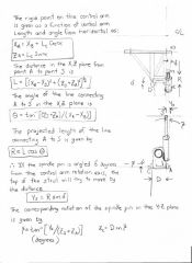
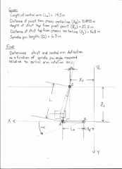
Can you make any use of Terry's example where he was able to get 1/8" deflection in the outer bearings by applying 130 ft/lbs of torque to the spindle pin? Seems to me like this distance can be converted into degrees and then that should be able to be measured in side force on the strut. EDIT--What would really be cool to find out would be how the control arm deflects when you go over bumps. Then you could get real world numbers for side force. The more I think about it and see the examples here the more I think I might just break down and make a new set of control arms. If for no other reason then not wanting to have to disassemble the strut to shim the spindle pin every time I want to make a toe change. Maybe I can use the inner tube from my modified arms, since Ron did some machine work on those parts for me... -
No, not full of mean people. Read the rules and you'll find that the rule about titles is #3. It's right up there at the top because it makes a huge difference when other people go to search for information. That's all. Read the rules and follow them and you'll find this board full of INCREDIBLY helpful people.
-
Search and you'll find posts of people installing them. You might also search "VW Beetle flares" as they are related. I think they look good, although that is a subjective thing. They only add about 1.5 inches as I recall so not very wide. You'll see all that info when you search and read for a while.
-
Start another thread and I'll give you my opinion. I don't think its appropriate to do it here.
-
Good point.
-
If it's that clean sell it on ebay with a high reserve. Spend lots of time getting super clear pictures, make the ebay listing very professional looking and clean. Some people have been paying really stupid prices lately. See if you can get some dumbass to pay you twice what it is worth and then buy a Z that already has a V8 in it. The other option is to build that one knowing that it is a solid chassis, but if you like to drive and not turn wrenches, then just buy one that's already done up.
-
Yet another Rear control arm design
JMortensen replied to tholt's topic in Brakes, Wheels, Suspension and Chassis
Dan sent me this and asked me to check it for accuracy... Well I'll leave that up to you guys, but along with the pictures is a spreadsheet that more accurately quantifies all of this info. I tried to upload it here, but apparently you can't upload Excel spreadsheets to the Hybrid Z server. So it's hosted at my business site. It might help to show graphically how the misalignment of the strut shaft takes place. The force that the strut shaft absorbs resisting this misalignment is side force on the strut. http://www.thepetdoorstore.com/rearstrut.xls -
-
-
I can't tell you about ITS legal. I'd imagine it would be legal but some sniveler might know how to determine which are the later ones and say that you're using a truck diff in your ITS car. Not sure if that would be an issue or not. If they have them in stock, I believe that would what you're proposing would work. I know no reason why it wouldn't.
-
That is the Nissan LSD. There was a change in the ring gear size, I think it happened in the mid 70s (76???) and after this the ID of the ring gear changed. This has been discussed before but it's probably been 3 or 4 years. You can look it up. So the issue is that you'd need to have the later R180 for this to fit. Also, the factory that manufactures these supposedly had a fire and there are no more left and the tooling is destroyed (this is as of last fall or so). I'd try to order one and see if they come back telling you it is NLA.
-
Also you really wouldn't want to adjust toe at the inner rod ends because that would swing the outer end of the control arm at an angle. The farther the strut traveled from it's intended path (perpendicular to the inner control arm joints) the more bind you would put the strut shaft and the control arm in. This is a BIIIIIIIIIG no-no with an H arm strut setup. EDIT--Actually I think I'm wrong here. I was imagining the effect of moving one pivot up and the other down
-
We're agreeing here, I just remembered the length wrong. So you end up with 5/16" adjustment on each rod end, or 5/8" total. That is not how the toe adjustment works. It's not a linear 1:2 ratio of the threads to the toe change. There is some trigonometry involved in figuring it out, and I happen to suck at math so I won't try to explain it, but Terry Oxandale previously showed that it is not a direct relationship between the length of the thread and the toe change. The angle of the spindle pin change is what is affected and the diameter of the tire also affect the outcome. The bigger the tire the more coarse the adjustment becomes, I can tell you that much. This is not correct. On the stock vehicle it doesn't matter where the control arm is in relation to the horizontal. The Z gains negative camber until the control arm is perpendicular to the STRUT HOUSING, not the ground. It is correct to say that it gains negative camber a lot more slowly once the arm passes horizontal, but it is not correct to say that the camber starts to go positive past horizontal. I don't know if it is possible to lower the car so much or travel enough for that to happen. I want to say that it's nowhere near possible, but I'd have to check to be sure. Here is a diagram that shows what is going on also courtesy of Terry Oxandale: http://www.fototime.com/ftweb/bin/ft.dll/detailfs?userid={7DC317B0-8EDB-4B2E-A837-F708D07C9769}&ndx=19&slideshow=0&AlbumId={E19B86F3-5BFB-4733-AF72-09BD805A6F1A}&GroupId={832D28D1-26F8-4E35-B3D1-6BB2152C089B}&screenheight=768
-
There's ONE far superior way to solve the problem.
-
Probably the rest of the car looking fairly normal assuming it didn't dig a rim and flip. By whose definition? You saying "it's adequate thread engagement" or "the toe adjustment is fine enough" isn't enough proof for me. Aurora bearing says 1.5x the diameter of the fastener, so that's 15/16" engagement. Last I checked the threaded section of a rod end is 1.25", which leaves 5/16" adjustment. Here I was thinking that it was to raise the roll center. It's good to know that you did not have roll centers in mind, and it was actually the camber curve that you were thinking of. Especially helpful when you consider the negative effect that these will have on the camber curve. Better, but I still wouldn't trust it. There are many different ways to secure the brackets you've designed. Installing them in a nylon bushing with a set screw or a 5/16" bolt is about the least effective way I can think of.
-
So the sheet metal floor pan will prevent ANY force from moving your part no matter how loose? That's what would hit so far as I can see from the pics. Let's assume for a minute that the floorpan is strong enough to prevent movement. What prevents the inside tire in the corner from moving in the opposite direction in this example? Not in my opinion. Riiiiiiiiight. That's why racers are always trying to make their control arms shorter. I thought the rule of thumb here was that you want 1.5x the thread engaged in the arm itself, not that you just want it engaged in any thread. If there isn't enough thread engaged in the tube the arms would not be able to support the load, even if the rod end was fine. It wasn't the rod end that Kipperman broke on his arms: http://forums.hybridz.org/showthread.php?t=123263 There is nothing useful in this part of your post.
-
Your qualifications don't exclude you or your parts from criticism. Here are some of the problems I see with your arms and your statement above. You're figuring your shear strength wrong. It appears you've neglected to reduce the diameter by the depth of the threads x 2. You're loading a screw with built in stress risers (threads). I don't know exactly what that does to the numbers since I'm not an engineer, but it makes me want at the very least a larger margin of safety, and I'd want a relatively huge margin to account for metal fatigue since this thing is going to be constantly under stress. The nylon bushings are "tight". I've seen plenty of pressed on metal parts spin on their shafts, so "tight" nylon bushings seems like a bushing that will have some stiction, not a secure method to keep a part from rotating. You're telling people to rotate the brackets for the control arm up. The more perpendicular to the ground the bracket is, the more the leverage the control arm has on the bushings and the set screw. Raising the pivots isn't in itself a bad idea. The way that the brackets clamp in makes raising them in your design a bad idea. You've deleted your toe adjuster, so now toe adjustments have to be made one turn of the rod end at a time, which is a gross adjustment, not a fine tune. Terry Oxandale figured out that with a 3/4-16 rod end 1/2 turn of the rod end equated to 1/8" toe change minimum. I think you're using 5/8"-18 rod ends, so it might be a little finer adjustment, but still not exactly fine tuning. And unless the taps were started in exactly the same position on the front and back holes on both sides, it seems unlikely that the rod ends would be at the same depth for a given number of turns. That said I think it's unlikely that you could even get both wheels to point straight ahead. You've shortened the control arms which exacerbates the camber curve.
-
Yet another Rear control arm design
JMortensen replied to tholt's topic in Brakes, Wheels, Suspension and Chassis
I got enough other BS on my plate. I'll probably run my arms as they are for a while, and next time around delete the rear bar and do an arm like the drawing shows. I'm really interested to see Dan's when they're done. -
Yet another Rear control arm design
JMortensen replied to tholt's topic in Brakes, Wheels, Suspension and Chassis
It still seems so obvious to me as to what mechanism is causing the side load that I'm a bit surprised that Dan and I still appear to be alone in our opinion. That said, you're not bugging me at all. I'm here to test my theories and learn. I had to think pretty hard to analyze what makes the difference in the H arm and the tri-link strut design you posted, and I like that type of thing so thank you. In the end I think the exercise was instructive. In the tri-link suspension the links allow the strut to move fore or aft or rotate slightly without binding the links. In the H arm strut setup any of those motions would be resisted by the control arm. Failure of the control arm to control the force would then transfer it to the strut housing which has no freedom of movement in those directions. The strut is then forced to control the motion, which loads it like a beam. But it isn't a beam, it's a strut and so the relatively small connection between the upper and lower halves of the strut is the bushing inside the strut, which gets loaded and there's your stiction. -
Yet another Rear control arm design
JMortensen replied to tholt's topic in Brakes, Wheels, Suspension and Chassis
Seems to me that as the suspension compresses the longitudinal link will cause the suspension to swing in an arc. That would very quickly cause bind in the lateral links, if everything were solid bearings. EDIT--Actually, maybe that would just cause toe change. Still not what I'd be looking for. The RCVD book discusses this suspension on p642 as well. Binding is not mentioned as an issue with this setup, although toe change is and it's suggested as a good suspension design for compliance and ride comfort. RE-EDIT- The reason you don't have bind with this one (as much, still has some like any strut) is that the upright can pivot where the longitudinal link attaches and the lateral links allow the suspension to move fore and aft a bit. With the Z neither motion is allowed by the H arm, so any force that wants to move the suspension in those directions acts directly on the strut housing and causes the side loading on the strut. -
Yet another Rear control arm design
JMortensen replied to tholt's topic in Brakes, Wheels, Suspension and Chassis
I fail to see the Subaru's relevance. If you're thinking about bind, those giant squishy rubber bushings probably handle that. Replace all the bushings with bearings and then we could talk about binding issues. -
Yet another Rear control arm design
JMortensen replied to tholt's topic in Brakes, Wheels, Suspension and Chassis
I don't think you are right that since everything attaches to the spindle pin that there won't be any side forces. There will be side forces on the strut regardless of the pin length. Like the Millikens said, any flex in the arm will create side forces. Why? Because flexion lowers or raises one end of the arm, attempting to rotate the spindle pin. The top of the strut stops that rotation as you say, and the rotational force is applied along the side of the strut shaft, so it gets concentrated at the bushing inside the strut, hence stiction. Put the pressure directly beneath the strut shaft and there is no longer any attempted rotation of the spindle pin. About the toe link in compression, I'm not sure how you could design around that or whether it would be necessary if the strength of the link were sufficient.