

JMortensen
-
Posts
13742 -
Joined
-
Last visited
-
Days Won
68
Content Type
Profiles
Forums
Blogs
Events
Gallery
Downloads
Store
Everything posted by JMortensen
-
It was time to get rid of "Don't tase me bro"
-
Strange Wilderness is the movie, saw the commercial last night, was crying laughing after replaying it on the DVR about 5 or 6 times... http://www.youtube.com/watch?v=QbqFq1rbusg&feature=related
-

Anyone try using structural foam on their z?
JMortensen replied to SmogSUX's topic in Brakes, Wheels, Suspension and Chassis
Search for it. It's been done before. Downside is that it can trap water and rust repair is pretty much impossible. -
Yet another Rear control arm design
JMortensen replied to tholt's topic in Brakes, Wheels, Suspension and Chassis
I think I figured it out, you must be talking about the angle of the strut to the wheel angle. Yes, that absolutely will side load the strut as well, and that is as I understand it the major limitation of the strut suspension. That's why the strut is leaned inwards as I recall, so that under cornering loads the suspension can still move somewhat freely. I think the design is a compromise between straight bump side loads and cornering bump side loads. At least that's the way I had it figured in my mind. The point that Dan and I are trying to make is that you don't need to exacerbate that problem by adding a lot MORE side force to the system. -
Yet another Rear control arm design
JMortensen replied to tholt's topic in Brakes, Wheels, Suspension and Chassis
I'm not sure what a CL is. I'm pretty sure you're not going for coefficient of lift. Here is another example Ron. Take a shock with eyelets top and bottom. What comresses the shock without side loading: Pushing directly on the bottom of the shock, or putting a lever through the bottom eyelet and pushing up on the lever? Obviously if you tried to compress the shock at the end of the lever you would lift the shock until the eyelet bushings or the rod ends bottomed, and then the force on the shock would come at an angle. Same deal on our cars. If the pickup is directly below the strut tube, you should get no side loads from the weight of the car and the suspension in bump. You'll still get some side forces from braking, but that's going to be a lot less of a hindrance than what you'd see from the weight of the car or the suspension in jounce. -
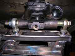
I really really really don't like the idea that a set screw holds this thing in place. The brackets appear to be in BUSHINGS. So let's say you come into a turn pushing 1g, and the outside wheel is going to feel 1000-1400 lbs of side load depending on the Z, which is going to be transferred through the arm to the brackets and into the gold tube, and then a SET SCREW is supposed to keep this whole thing from rotating? Seems like a recipe for disaster to me.
-
Yet another Rear control arm design
JMortensen replied to tholt's topic in Brakes, Wheels, Suspension and Chassis
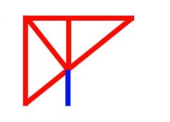
Actually now that I think about it the strut is really totally behind the spindle pin area. So that makes it even easier. It would be necessary to somehow weld a tab or bracket to the back of the strut housing so that the rear rod end was in double shear. It seems like it would be pretty easy to then use a longer spindle pin and just hook the toe link up at the front of the strut housing as usual. Arm in red, toe link in blue (duh): So who is going to make the first one? My money is on Terry. He always seems to be the first out of the gate, and I know how concerned he was about binding the strut shaft... -
-
Yet another Rear control arm design
JMortensen replied to tholt's topic in Brakes, Wheels, Suspension and Chassis
I was writing mine when you posted yours... -
Yet another Rear control arm design
JMortensen replied to tholt's topic in Brakes, Wheels, Suspension and Chassis
Now I'm wondering about cutting a section out of the tube that the spindle pin goes through and making an A arm that fits right up underneath the strut, then using a toe link (presumably in front because the strut tube is offset to the rear). -
Yet another Rear control arm design
JMortensen replied to tholt's topic in Brakes, Wheels, Suspension and Chassis
Here is something interesting from Milliken p 642: "One negative factor of this design (the H arm) is that any flex in the arm or distortion of the bushings due to braking loads or bump loads causes side loading on the strut." That sounds familiar! Of course I've read the book, so maybe I can't take credit for that. Certainly I think it proves my point about the A arm toe link modification to the Z strut. It goes on: "With strut side load comes friction or resistance to axial motion. The suspension cannot isolate and perform all of its other functions properly when friction is present. This suspension has been thought of as a lower cost version of the A arm and toe link. It almost is, but not quite because of this potential for causing friction." And after reading this I had the eureka moment. What would be necessary for the A arm and toe link to work without putting side loads on the strut would be for the A arm to terminate directly below the strut shaft. If you had that, then you could pivot all you want with a toe link and it makes no difference. That also answers your question Cary about why the WRC cars can do it. Cameron, since my entire suspension is on heims joints there is no slop in there, and I can assure you that there will be very little movement up top. Terry Oxandale and I hemmed and hawed over what the result would be of the lack of flex in the system. -
Yet another Rear control arm design
JMortensen replied to tholt's topic in Brakes, Wheels, Suspension and Chassis
Absolutely no argument from me. The issue is that it could be better. I'd agree that the stock arm is pretty weak. But the stock chassis is pretty weak too, as are the stock uprights in the rear suspension. Just because they're weak doesn't mean that they weren't intended to do a job that they're really insufficient for. I'm not sure what you're getting at with the last part though. I ran my suspension through it's travel and watched the top of the strut and shimmed the strut back and forth on the spindle pin until I saw that the strut stayed centered throughout the entire motion of the suspension. With that said, I fail to see how a rigid control arm which centers the strut could make the strut "see more stress". Plus, I don't think the force that will get to the strut will be linear at all with the toe adjuster link. I mean, you hit a bump and there is going to be a spike in side force which will tend to make the strut want to bind right at the point where it should be moving. That's my uneducated view of it anyway. Am I missing something? -
What is the purpose of using the Toy damper? Seems like a lot of effort, it might leak, and there are BHJ and ATI dampers available for the L that actually fit if you didn't want to use the stock damper. As 1 fast z said, they don't do external damping anymore, so there won't be a difference between a 6 cylinder damper and an 8.
-
Yet another Rear control arm design
JMortensen replied to tholt's topic in Brakes, Wheels, Suspension and Chassis
You could do something like John has done coupled with my/blueovalz's/jeromio's "poor man's toe adjuster": http://forums.hybridz.org/showthread.php?t=89111 -
Yet another Rear control arm design
JMortensen replied to tholt's topic in Brakes, Wheels, Suspension and Chassis
I think there were some formula cars that were designed with an H lower control arm and an upper link. I've been looking in some books and can't find an example, but I'm sure I remember reading that, and I thought they were F1 cars. I thought I read that in Competition Car Suspension, but I can't find it now. I did find a similar setup in Race Car Vehicle Dynamics, but it's just listed as a type of suspension and the car it's referenced with is a 90s T-bird, not exactly the pinnacle of performance, but I think it proves the concept of controlling the twist with the lower control arm. I think the control arm can do the job just fine, if the arm is properly designed for the job. Back to our cars for a minute, I think this is the key point: If Nissan didn't want the control arm to deal with those twisting loads at all, they could have easily designed a lower A arm and a toe link instead of the lower H arm that the car got. I think the fact that they used an H arm is proof of what the arm is intended to do. Yep, that's one reason why I was so hesitant about the clevis link to the rear part of the arm. That could be a solid tube welded in and then the design would be a lot better in my opinion. Tom, have you looked at John Thomas's arms (post #36): http://forums.hybridz.org/showthread.php?t=106457&page=2 -
Yet another Rear control arm design
JMortensen replied to tholt's topic in Brakes, Wheels, Suspension and Chassis
Forget about the toe link for a second. Imagine you have a triangular arm which attaches to the stock front and rear inner pivots and to the front of the strut housing. There is no strut insert in the strut housing for the purpose of this example. Set the car on the ground, and the strut housing will rotate forwards (would turn in the same direction as the wheels when driving forwards) until the monoball binds. That's just with the weight of car, so think of the force on the strut when you hit a bump in the middle of a corner Now add a rear toe link and it does the same thing. Tom's arm is so weak in the back that it would also do the same thing. The stock arm is pretty weak too, but my modified arm (and Terry Oxandale's and John Hines's) has a large tube which would prevent that twist. Here is a pic: I think that twist is significant because the main issue with strut suspension as I understand it is the stiction created by side forces on the strut housing when turning. That lateral force wants to lock the strut so that it can't move. But now you've designed a control arm which by design increases the amount of side force on the strut. In a game where people are putting torrington bearings on the ends of the springs because the spring windup causes unwanted forces on the strut it just seems to me like you would want to avoid loading the strut if at all possible. This is one of the very few things that I've really disagreed with Cary on, but I really think I'm right on this one. -
-
Yet another Rear control arm design
JMortensen replied to tholt's topic in Brakes, Wheels, Suspension and Chassis
That's how Cary ran his control arms if I recall, except he had a full triangle in the front part with 3 rod ends and then a toe link at the rear with 2. The problem I have with that design is that the bottom of the strut isn't held perpendicular to the ground and the rear toe link (or the rear part of Tom's arm) don't prevent the strut from twisting. That twisting imparts a side load on the struts. Struts already have issues with side loads without adding more into the equation. It might work, but it's not optimal in my opinion. How much less than optimal it is is up for debate. Seems like Cary was going pretty fast with his old arms from what people tell me. -
Yeah, I just thought it fit here perfectly.
-
Here's an 80's throwback for you: http://internetisseriousbusiness.com/
-
AAAAAAAAAAAAAAAAAAAAAAAAAAAAAAAHHHHHHHHHHHHHHHHHHHHHHHHHH!!!!
-
Yet another Rear control arm design
JMortensen replied to tholt's topic in Brakes, Wheels, Suspension and Chassis
You say you're looking to change the track width? I would caution you against running too much exposed thread on the rod ends, according to the rod end manufacturers they want 1.5x the diameter threaded into the tube end, which gives you only 5/16" adjustment on a 5/8" rod end with a standard threaded tube end that is 1.5" long. This is a highly stressed area and while I think I might stretch those recommendations elsewhere I wouldn't here. That said you could simply get longer turnbuckles to make the arms longer. The arm itself doesn't seem like it would be very rigid at all. The angle of the link from the inner rear pivot to the outer front pivot essentially makes it good for nothing. I realize that in the drawing all it is doing is holding the front rod end setup horizontal but it really isn't positioned to do even that job very well. A shorter arm positioned perpendicularly to the clevis would be better. It seems like those clevises would be under huge amounts of stress, since they take all of the load whenever the strut doesn't just want to move straight up and down. All of the accel and decel loads that the arm takes, and also all of the cornering loads are going straight into those clevises. It's asking a lot of those parts. Too much for my tastes. If you were going to the trouble of starting from scratch with the arm and the chassis mounts, seems like the thing to do would be to move the pivots to the center of the car and make the arms as long as possible. This would also get rid of the uprights behind the diff and I think that is a particularly weak part of the original design of the car. You could improve on that quite a bit if you wanted. Also if it were my project I would tie the front and rear rod ends at both the strut end and the chassis end together much more securely than your proposed design. Your design would allow for a lot of side force on the strut shaft. My engineering degree doesn't exist, I took trigonometry 4 times before passing, and I sell doggy doors for a living, so keep in mind who is criticizing you... -
Basically you need the belt pulley to line up and I'm guessing you'll probably have to switch the water pump and alt and whatever else you're running to serpentine. I think that's the only other main issue, assuming it clears the timing cover. If the diameter is wrong you'll have to make a pointer for the timing marks.
-
NOS Datsun Nissan Comp Race Fender Flares on Ebay
JMortensen replied to RB26powered74zcar's topic in Non Tech Board
OK, guys, both of you knock it off. -
Is that the same car that used to have the L6 mounted about 1/2 way into the passenger compartment?