-
Posts
30 -
Joined
-
Last visited
Chickenwing's Achievements
-
Chickenwing changed their profile photo
-
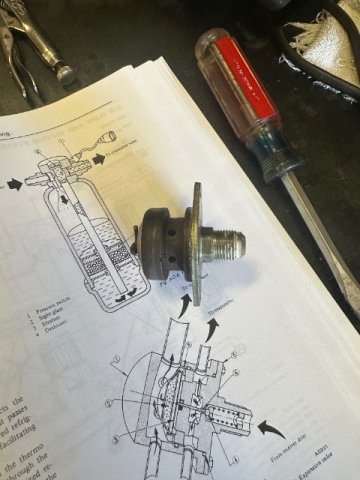
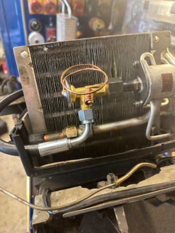
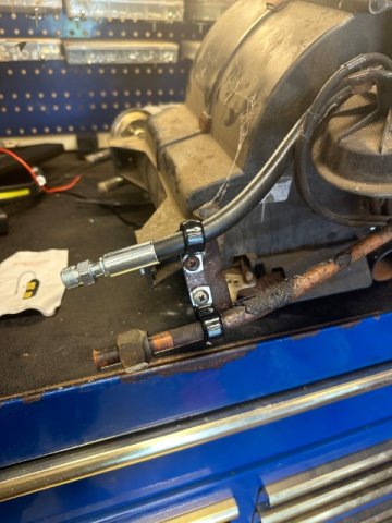
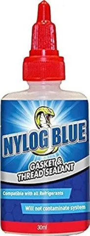
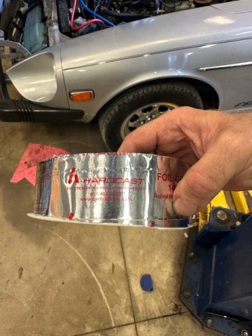
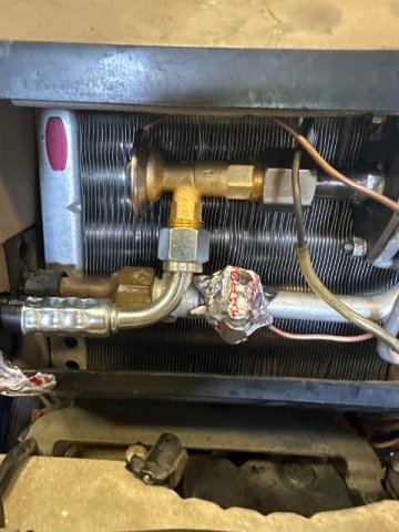
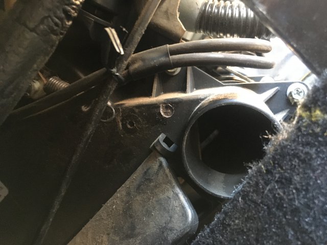
Edit: 75-78 280Z. I am editing this post to add my expansion valve modification. It will take a while to finish this post be patient. Yes I will add part numbers. End edit. If anyone is looking for the stock expansion valve o-rings which are NLA, for the outside sealing ring use a 1-1/2”id x 1-11/16”od x 3/32”cs also known as AS568-128 HNBR. The inside ring is 1-1/2”id x 1-5/8”od x 1/16”cs also known as AS568-029 HNBR. I purchased mine at www.Theoringstore.com . It took a few tries. Hope this helps somebody. Edit: EXPANSION VALVE MOD. First off, I don’t believe this mod is for everyone. If you have the $, my recommendation is to purchase Auto AC Solution’s new evaporator core. 1. They have the expansion valve in the proper orientation for longevity. 2. They put in the work to design this thing and deserve a return on their investment. 3. Your evaporator is barking 50 years old. https://autoacsolutions.com/products/1972-1973-1974-1975-1976-1977-1978-datsun-nissan-240z-260z-280z-a-c-evaporator-core-with-expansion-valve-factory-direct-drop-in-replacement/ One caveat though, the FSM shows replacing the evaporator with the dash installed. I believe this near impossible. To do this mod you will need: 1. AC hose crimper set. 2. Four Seasons #38616 expansion valve. 3. 2 feet of #6 reduced barrier ac hose. 4. Straight Reduced Barrier male #6 o-ring fitting. Four Seasons #18086. 5. 90 degree Reduced Barrier female #6 fitting Four Seasons #18086. 6. Straight female flare OR female o-ring STEEL fitting. 7. If you select #8 female flare, you will need a #8 o-ring to flare adapter. Four Seasons #16748. 8. Tig welding capability. 9. Drill bits as close as possible to the outside diameter of your #8 steel fitting tube. 10. Dremmel tool with burrs and cut wheels. First mount the valve in your vice using soft jaws or wood blocks. DO NOT MAR THE O-RING BEARING SURFACE! Next working up to a 1/4” bit, drill to remove the orifice tube (6.) Once the orifice tube is removed, continue drilling all the way through the bulb (1.) Use a dremmel tool with a burr to remove the bulb and the material inside. DO NOT KNICK THE O-Ring BEARING SURFACE! (Warning: I do not know if the material in the bulb is hazardous. The material is black graphite looking flakes. Recommend a dust mask at minimum.) You will end up with this. Later, you will weld a bolt in this hole. Now look at the first pic. Cut off the “nipple” of the valve just even with the nut boss. (That sound bad doesn’t it?) Do not cut the boss off. You need the material for welding. Now measure the outside diameter of your selected #8 female STEEL fitting. You need a drill bit as close as possible to that size. (Note: I elected for the flare fitting. I used an original one from the hoses I changed going to the condenser. The Datsun fittings have a very hefty wall thickness and I wanted the thickness for weld “meat”. I can’t tell you the thickness, as I had mine machined to almost an interference fit.) You will drill out the boss only to the top of the expansion chamber. DO NOT DRILL PAST THE EXPANSION CHAMBER. The expansion chamber is the hollow just beneath the ball seat (4. In first pic.) You now need to cut the barb off your #8 straight female STEEL fitting. I did this in multiple steps and did not take a final measurement. This is what you need to consider: 1. The depth of insertion is flush with the top of the expansion chamber ceiling. Do not block the expansion chamber outlets with the fitting. 2. You want as small of an assembly as possible. Too long and you could run into clearance issues inside the evaporator suitcase once you mount your new expansion valve. 3. The fitting needs to be long enough to allow full pull back of the b-nut so you don’t risk cross-threading the b-nut on your new expansion valve. See next pic. Remember that 1/4” hole on the other side? Select a bolt which fits the hole. Cut the shank down to where it does not enter the expansion chamber. (If you are wondering why you removed the bulb now, there are two equalizing orifices (#8 in first pic) which lead to the expansion chamber. Their purpose is to allow pressure equalization so the diaphragm may operate independently of pressure. Failing to defeat this would allow refrigerant to bypass the evaporator.) Weld everything in place. I took mine and had it tig welded as I did not trust my own skills. The above jumps the gun a little bit, but I didn’t take pics of the final product. Notice how little room there is from the edge of the hose fitting to the wall of the evaporator housing. The suction hose needs about that much clearance so it may bend without kinking. Dremmel a 1/2” hole in the evaporator case centered in the space available next to the #8 suction hard line. Sorry no pic again, but you can see where the hose passes through the wall. Now fabricate your hose. (My hose was cut to 22-7/8”. Your hose length will vary due to your insertion depth of your expansion valve modification and fitting lengths are different between manufacturers.) Step 10 will cover hose fab taking into account these differences.) That will be long enough to take into account small variations in fitting sizes. One end will be a #6 male o-ring straight and the other a #6 female o-ring 90 degree. With one being a straight fitting, you may ignore fitting clock orientation. No pics for a while now. Time for the actual install. 1. Evacuate system. (Environmentally conscious of course.) 2. Disconnect #6 high pressure fitting at bulkhead and remove bulkhead grommet cover and grommet. 3. Use dremmel cutting wheel, cut #6 copper line at each hold down bracket on the side of the case and before the b-nut on the existing expansion valve. 4. Remove all #6 copper lines. Leave the brackets in place to hold the #8 line. (The bracket hold own screws are impossible to access.) 5. Dremmel a 1/2” hole in the case in the space next to the #8 copper line. Be patient. Don’t nick the copper line! 6. Vacuum up all of your debris. 7. Remove expansion valve and modify it. 8. Install modified expansion valve. (Note: I had wire wheeled the o-ring bearing surface on my valve multiple times. Resultantly, my new green o-ring for the inside housing no longer fit. I ended up using an old black one I had saved. 9. Install new expansion valve. If you used a #8 female flare, you will need the flare to o-ring adapter. Use nylog to lubricate the o-ring and the sealing faces of the flares. The expansion valve comes with a #6 flare to o-ring adapter. Keep it, you will need it later. Don’t worry with the capillary tube yet. 10. Crimp the straight male hose end on your hose and insert through the 3/4” hole in the case and route the hose as in the pics above. Temp install the straight connector onto your copper flare connector. Do not torque. Note the hose is between the vacuum actuator and the case. I did NOT clamp this hose in place. My pictures are from my mock-up. The screws for the brackets are impossible to remove without removing the entire evap case housing. 11. Temp Install the female 90 degree hose end to the expansion valve. Make a mark on your hose and cut long. Cut your hose shorter if necessary to have proper insertion length in the ferrule. Unscrew the straight fitting and 90 degree fittings. Pull the hose out far enough to crimp the 90 degree fitting to the hose. Reinstall the hose assembly by temp installing the 90 degree fitting first. (This is important to avoid orientation issues.) Don’t forget to nylog the o-ring. 12. Install the male hose fitting on the female copper fitting inside the bay utilizing the #6 flare adapter that came with your new expansion valve. (I attempted to reuse the original screen filter but it did not fit inside the male o-ring fitting.) Don’t forget to nylog the flare faces and the o-ring. Note: the flare adapter fell out for me and I did not notice. This resulted in a MASSIVE leak which caused me to run down a rabbit hole researching new engine bay part. -then I found the adapter underneath my car. 13. Carefully unwind the capillary tube and use a hose clamp to hold it snugly against the evap outlet tube. Position it as close to the B-nut as possible. This is to allow the evap to get as cold as possible. SNUG! Don’t crush the capillary tube. The goal is to insure contact. Ensure the capillary tube does not chafe against anything. I used this stuff to insulate the capillary tube and patch up the resulting holes in the evaporator case. It’s pricey, but it was left over from me cleaning my home’s evap coils. You can buy it at your local HVAC supply. And that’s it. Put your panels back on and service per FSM procedures using pressure charts for your desired refrigerant. I use Duracool. 43% humidity, 93F. Fan clutch engaged. 1500 RPM. Windows up. Car in shade.
-
It’s an old thread. Just saying thanks for the lead.
-
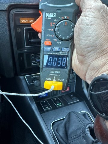
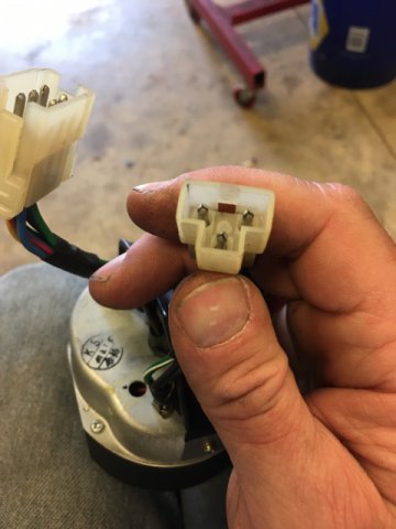
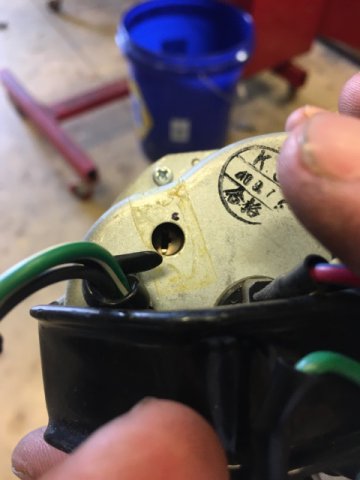
Via FSM determined steering lock switch shorted to ground causing blown 10a Hazard Fuse. Disconnected steering lock switch -ops check good. Well, sorta. Voltage was reading way too high showing close to 16v and I know my stock one struggles to put out even 15v. Removed gauge and found an adjustment set screw. Determined the top left pin (with the index pin pointing down) was positive (it has red tape around it the wire) and the top right was negative. Hooked it up to the battery with the engine running. I used some molex pins I had on hand to make the test leads. Used my multimeter as a reference and determined idle voltage was 14v flat. Made an index mark so I could go back to home. It was intuitive from there. Clockwise increased the reading, counterclockwise decreases the reading. Reads as it should now. This also fixed my hazard lights as that circuit also feeds the hazard light switch. Hope this helps some puke in the future. Reference pages on 77 FSM: BE39 gauge removal. BE-33 schematic/diagram.
-

wheel info (american dragmasters?)
Chickenwing replied to s30zgt's topic in Brakes, Wheels, Suspension and Chassis
Digging this back up. I have the same wheels. I have two center caps if ya want them, but they are not show quality... By chance you know what length/diameter lugnuts these take? -

1977 280Z dash vents not blowing
Chickenwing replied to Chickenwing's topic in S30 Series - 240z, 260z, 280z
Thanks to both. I’m sure plenty of other stuff breaks in the climate control system. That’s why Step 1 is “Verify Fault.” If anyone else has other faults to add on please do so. It is SO nice when you google a problem and TaDa! a legit answer pops up! -
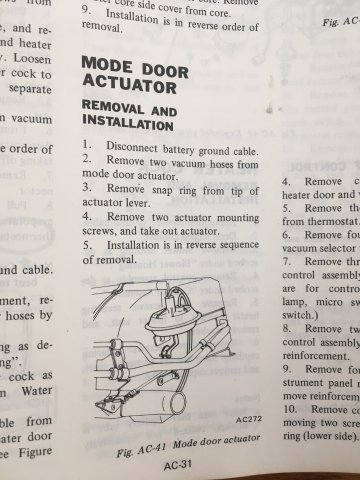
This has probably already been figured out, but here is a fix if someone searches this forum. 1977 280Z. Problem: Air will not come out of dash vents at any climate control lever position. Cause: Mode door actuator not retracting to close heater plenum due to broken plastic boss at retract spring mount bracket on Heater plenum. Part location: Just above left hand side defrost outlet. Applicable 1977 FSM pages: AC-31 Figure AC-41. NOTE: The offending broken piece is NOT in front of the heater core or evaporator core. This repair is safe. However some common maintenance practice is required. Non-standard Tools needed: Drill, Pop Rivet gun, applicable size drill bit. One applicable size aluminum pop rivet. STEPS: 1. Verify fault condition. 2. Remove left hand seat. 3. Gain access to the return spring bracket. 4. Disengage the spring from the bracket and let it hang from the mode door actuator rod. 5. Remove the bracket if necessary to finish removing the broken boss. 6. Reinstall bracket and center the bracket boss hole in place where the broken boss was. (This will be your drill index.) 7. Decision time. A 1/4” aluminum rivet repair this nicely. However, most hand rivet guns which will access this space only go to 3/16”. You may attempt using this or procure a gun which will handle a 1/4” rivet. I elected to procure a HF pneumatic Rivet gun. (Because I am a tool whore.) 8. Using a drill matched to your chosen rivet size, AND using the bracket whole to center your drill bit, use low pressure high speed to drill the rivet hole. The plastic may be brittle. High pressure or low speed may cause your bit to rip a chunk out instead of creating a nice round hole. 9. Rivet bracket to heater core housing. If using 1/4” rivet length of 1/2” should be fine. If using 3/16” use a washer on the head side to take up the excess space and go up a size in length to ensure there is enough “mushroom” on the backside. The good thing about the 3/16” is if it fails, you have a chance to go up to a 1/4” as a subsequent repair. As the rivet is in sheer, I don’t THINK it will fail if installed properly. Also remember to ensure you are pressing the bracket tightly against the housing when you squeeze the rivet, other wise you will end up with a loosely fitting bracket and cycles will eventually fail it. 10. Reinstall return spring. Verify the spring is in the indexes. The spring is surprisingly strong. Needle nose pliers are helpful. 11. Verify fix. 12. Reinstall seat and done. Hope this helps someone. FYSA: The first pic is on my daily. The second two are on a heat/ac box I had laying around. I needed to verify the repair before proceeding on my daily. Edit: I had my instrument panel under cover and center console removed for installing carpet, so I don’t know if it is required for this repair. (It sure was easy with them removed though.)
-

280Z Restomod Progress
Chickenwing replied to dmoralesbello's topic in S30 Series - 240z, 260z, 280z
These boots are nicer than the ones I installed. My old pins didn’t fit either, but the kit came with new pins and crimping was pretty straight forward. Post up your supplier on these! -

Zedd engine frame rails issue...?
Chickenwing replied to FairladyGTR's topic in Fabrication / Welding
Any more traction Fairlady? It will be a pain, but if you are able to remove the rail without molesting the radiator support, you should be able to massage the support to fit. It will take rebending the flanges to the correct height, but everything else would get to remain the same. -
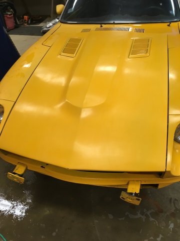
I used my detail gun. I shoulda used my hvlp. I thought I would save it for the clear and just throw the detail gun away. Oh well. It's kind of a Ratsun thing for now anyway. Clear coat tomorrow.
-
Masked it off for the orange. The blue does look surprisingly good with the yellow! Hope the weather holds so I can spray it tomorrow.
-
-
-
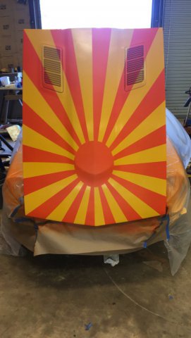
Just rubbing her out to keep motivation to the max. Not much I can do on drill weekend. Think I'm gonna try and paint a Japanese war flag on the hood this coming weekend. Lol
-
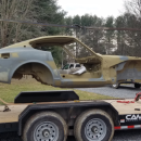
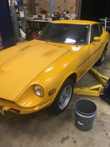
Ok. New chassis. 77 with an Oct 76 build date. She's kind of a cocktail waitress wearing a Dolly Parton wig with the Godawful yellow makeup, but she has good bones.
-

