

1 fast z
-
Posts
1159 -
Joined
-
Last visited
-
Days Won
8
Content Type
Profiles
Forums
Blogs
Events
Gallery
Downloads
Store
Posts posted by 1 fast z
-
-
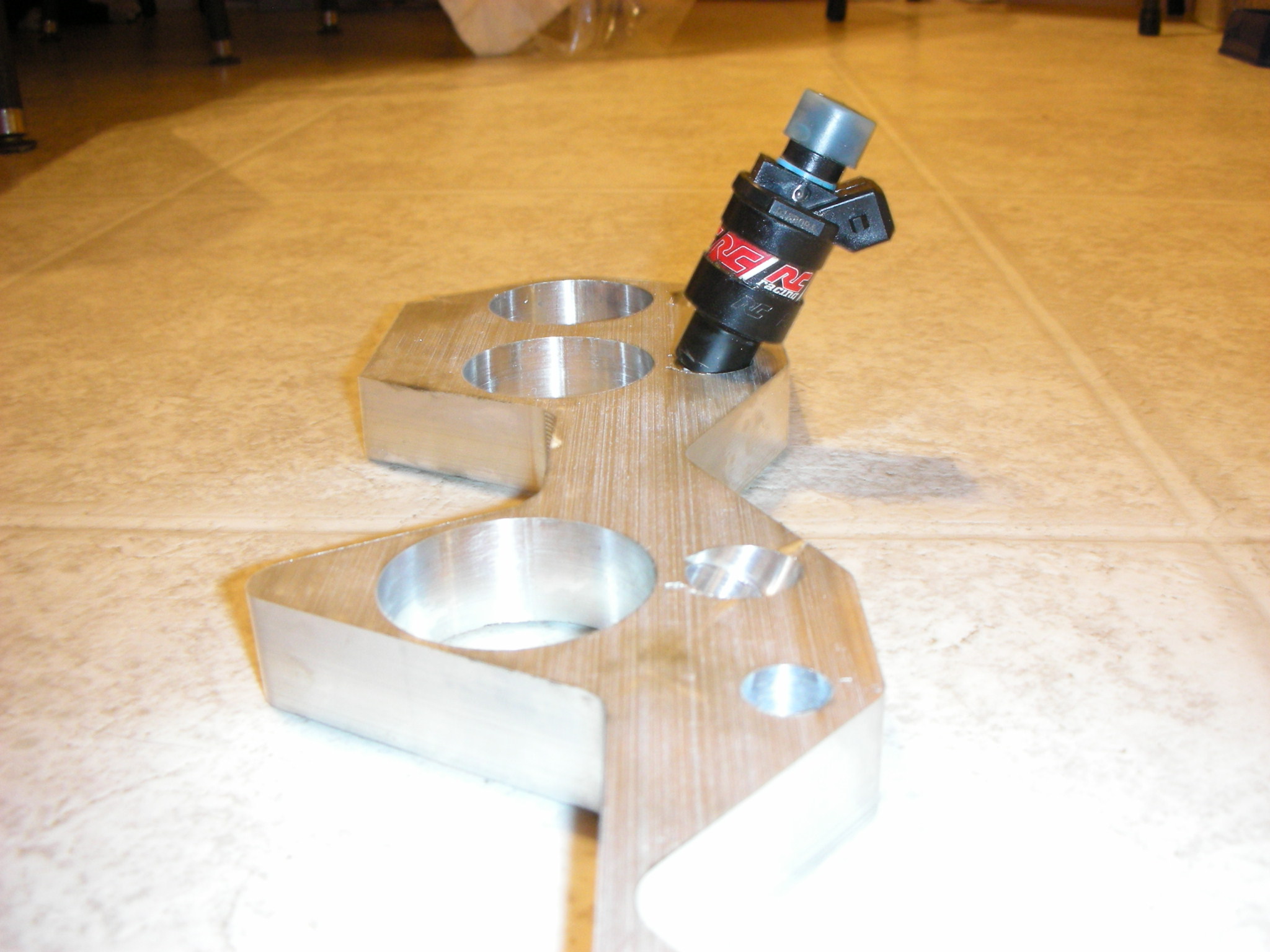
Here are some shots of the 14mm injector bored holes. 25 degree angle. Pictured with RC injectors.

-
Obviously tony, you would get the "tony discount" HAHA.
-
Only three avalible now, three are already sold, just a heads up.
-
Keep a .187" thick dome for NA cars, and .25" thick for Turbo Cars. I have done LOTS of lightening, as well as dishing, custom domes, etc.
NA pistons
Notice the extra strut inside the TURBO pistons for support:
-
Nope, flanges are .625" thick, works great with nismo headers, as they are .625" thick also, or close enough.
-
I built a flange for the average person, so that they can afford one. Not trying to impress anyone, as I do that with time slips on my own cars. These are just out there for the low spender that wants to build there custom intake. As far as a solid drawing, if thats what impresses you, then WOW. I am certified in mastercam, as well as solidworks, so solid drawings are EASY.
-
Ok, I remachined them, and tested against a turbo manifold, header, and NA manifold, and all clears perfectly. Heres the new pics. By The Way, the surface finish is alot better than the pictures depict.
-
I see, it, Ill fix it, Ill throw them in the cnc in the morning, to get it done, thanks.
-
Yea I had to make a flange for a custom intake, so I figured I might as well build a "few" extra.
This machine works great for doing them.
-
Ok, so here is some pictures of what the manifold flanges are. They are shown without the injector holes, as that is on a order basis, as some people want to put the injectors somewhere OTHER than the flange for atomazation reasons. They are
made on our Matsurra 1000VS2 Machine. They have 1.625" Intake Bores, which is perfect size for
1.375" ID tubing. They are all profiled on our CNC as well. No bandsaw cutting here! Great start to
get you started on your own custom intake, as you can build an intake pretty easy once you have a
Flange. Will fit all cylinder heads that came on a 240z, 260z, 280z, 280zx and L6 Maximas. Price is
160 without Injector Holes, and 190 With. Some people put the injectors up away from the head for
better atomiziation, so thats why we give you guys the choice. Pictures are shown without injector
holes. Intakes should always be port matched for better performance to YOUR head, and port job.
Web Site is here http://www.bandmzcars.com
Intake Page is here http://www.bandmzcars.com/IntakeFlanges.html
-
Just thought I would throw this out there, is that I have 2 extra CNC'd intake flanges up for grabs. 225 a peice.
-
Cast pistons, cheap bearings, cheapo machine work, parts and all would be about 3500.
Forged, good internals, GOOD machine work and head work, 7-8 grand with labor.
-
When you say stage two heads, are you talking 70's stage two heads?
-
Ok, I need a slip yoke that will fit the zxt t-5 tranny, and also accept a 1310 series u joint. Does anyone have a part number for a spicer or other brand slip yoke?
-
Clifton is the dual head gasket master! He stacks them on everything!! LOL.
-
I port a P90 about once a month, here is one of my customers. It can be done be doing it yoursef, but I would recomend a flow bench.
Here is a P90 head I ported, Flows 225 CFM@ 25" of water, compared to a 172 stock. On the intakes that is. The last two pictures are just to show what .010" difference in lash pads does as far as moving the wipe patturn in or out. Customer didnt want Polished Combustion Chambers, but it still turned out great.
-
Ok, guys, new updates coming I hope tomorrow. I have the cams finally finished machined, and drilled for internal oiling, I had to gundrill a .25" hole all the way through them. Then lots of timing calculations to get the cam timing dead on. Now hopefully the thread doesnt get closed again, so I can post pics!.
-
Well took the ole silver car out to autocross today, and took it for a few spins. It is ALOT better than last year. It could still use some toe out in the front, and I could be a LITTLE smoother on the throttle (DAMN ITB'S!) and steering. I had a few people from here ride or drive my car which included, IanZ, John Coffey, Frank280zx, and a couple other people I didnt know. I was turning consistant 69 second times also. I finally have a working spring combo with 300 in/lb in the rear and 250 in/lb in the front. I was running 3 degrees negative camber up front, and 3 degrees positive caster up front, with 1/8" toe out. In the rear I was running 1.5 degrees negative camber out the back with 1/8" toe out. Anyways just thought I would share what works good for me. The comment I loved the most was "this car certanly has the power" , or "this car has too much power" HAHA. I could use a little more cam though, as we were hitting over 7200 rpm on the last straight away in second, with the 4.38 LSD. I am running 520 lift with 286 duration, I might give it ten more degrees duration.
-
Dash Pot.
-
There is ALOT of cost in time that has gone into this project. Over 500 Man hours Between my father and I for sure. We have been doing LOTS of calculations, trial and error, quality controll, etc. The pics just show ideas. The ORIGINAL idea WAS mcadams Idea, plain and simple, and he came to me with the idea and we worked on some first ideas that some worked and some didnt. he then had to move to Minn. So he does recive credit for the ORIGINAL idea. Its not too dificulet to come up with an Idea, but making the idea WORK is the tricky part. Just like you cant patend an IDEA, per say, but you have to show a working model or proof of it. Lots of people have been telling me to patend this working model when its running, im not sure yet though. Like doweling the heads together, Im not going to post on the boards HOW we located, Where we located from, to be so precise. The pics were taken of the thirds before some final critical opperations were made, for the reason that we dont want to give out all of our secrets, but just to give you guys an idea on HOW it works. Im not going to go into detail on how we got the tie rods to be EXACTLY parrelell and perpendicular to eachother fron the rear of the head to the front, as they HAVE to be exact or they WILL exert forces in un-wanted directions and cause un-even clamping and therefore a possibly leak. These heads were off of two different KA engines also, and they were cut at different thicknesses in past time, as well as warped. So these pics give the basic idea, but FAR, and I mean FAR from the whole story from an enginerring aspect. MANY, of people on the boards, said to just weld the heads together, or JB weld them. Those ideas would of never worked, they would of created MANY forces/stresses that could of NEVER been taken out and therefore un-even cam wear, as well as rotaters, etc. As for a valve cover, its a full sheet metal one, thats completed, but dont have the camara here at the shop, but pics will be up soon.
-
 1
1
-
-
Well, half the head as far as EDM cost goes is yours, but engineering and Labor to this point is My dads and I! LOL.
We are making doubles of what were doing, as my dad wants to prove this head on a NA car, so Were going to put the head on a flat top 3.1 liter that is in my silver 77 car.
-
Here also is the head installed on the block with cams installed.
-
Ok, Heres an update on 4-24-07.
Here I am boring the rods on the CNC for full floating pins using alluminum bronze bushings.
Here we are setting up the rear third of the cylinder head for dowell reaming.
Heres the block right after the block was done with machine work, and painted.
Here are the ARP Main Studs Installed, getting ready to check for bearing clearences.
Here is the crank inserted.
Here is the VO7 Crank, as if I would use anything else, HAHA.
Here is the rear third with the dowells installed for alignment.
Here are the TIE RODS that clamp the entire head together for the force of gasket surfaces to be clamped. The tie rods are made out of 17-4 Precipitating Hardening Stainless, for a high yeild strength.
And here the head is semi complete. Its Dowelled, Has the correct gaskets installed, and tie bolts.
Here is how we attached the LOWER tie bolts to some blocks that we precision dowelled and counter sunk screwed to the front third head.
This is the plate that bolts to the rear third head that the four 17-4 tie bolts go through and use as a clamping plate.
Here is how the UPPER tie bolts attach to the front third head, we threaded right into the thickest part of the casting.
Pic Of the tie bolts again.
Here are the FORGED piston pictures, after I lightened them ofcourse. They have a mass of 325 grams, thats WITH a 250 thousands of an inch thick domes.
Notice the strut that I left the center of the piston for strength.
25cc dish for a 8.25-1 Compression ratio, with KEEPING quench pads, VERY important.
.125" wall A-2 Tool Steel wrist pins, full floating.
Wrist Pin bushing installed with oil hole, on ONE side.
Crank Installed after maintaing a .0012" Oil Clearence.
Updated Timing Pictures, We decided not to use the geared sprocket idler, after some calculations, the forces would of been too high, so we modified some stock L series guides pretty heavily, and a few other tricks that are kept secret and here we are.
Final Test Fit of the block and head.
Pistons Installed.
And the paint on the car didnt look good at all, so we through a "quicky" paint job on it for the time being.
-
So Im building a L series TWIN turbo setup and have some questions. Does a RB26 use TWO oil drains in the pan, or do they use a TEE in the system and one drain nipple in the pan? If so what are the sizes of the drains? Thanks guys.


Intake Flanges are finished and Ready
in Nissan L6 Forum
Posted
Obviously not debured, etc. So no flaming for dumb crap. Its just pics to give an idea.