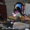
240hoke Posted April 9, 2005 Share Posted April 9, 2005 Hey, I jsut got done mocking up my t/c rods. I am using 1/2" qa1 heim joints opposite thread and chromoly tubing (.065 wall thickness i think) Anywa I have it mocked up and wanted to share it with you guys before I weld it up in case there is some problem ya'll forsee. Please lemme know what you think Oh I also plan on boxing in the tabs for more strenght -Austin Quote Link to comment Share on other sites More sharing options...
Jolane Posted April 9, 2005 Share Posted April 9, 2005 The thing that pops out at me is that you do not have anything that limits the LCA from rotating fore and aft. Most T/C rods control this but rigidly attaching to the LCA. While there probably is not much force in this direction, it is important to limit the angle that the ball joint operates. I am sure someone else will rpvoide more info. I would look into using a a Ford T/C end commonly available. You could also use a clevis at the LCA end instead. Joshua EDIT: Now that I look at it, it is VERY important to have a rigid connection at the LCA. Otherwise, the LCA will rotate about the inner LCA rod end and the T/C rod end, effectively buckling backwards. I really don't think this method will work. To test or see what I am saying, push back on the spindle. The LCA and the T/C rod must make a rigid triangle. Quote Link to comment Share on other sites More sharing options...
74_5.0L_Z Posted April 9, 2005 Share Posted April 9, 2005 Jolane is correct. You have one too many degrees of freedom in your set-up. What you can do is cut the stock tension compression rods down and keep just the ends that bolts to the control arms. Cut them so that you have about 6" of rod after the bend, and have the 5/8-18 threads turned on the rods. Then of course you will need two new (5/8-18 tube adapters). Bolt the ends in the stock location, and thread them into your tubes. Quote Link to comment Share on other sites More sharing options...
buZy Posted April 9, 2005 Share Posted April 9, 2005 Nice work by the way Austin! Yes it looks like too much freedom movement of the LCA. Here is another solution. Take the TC rod you made and just replace the LCA rod end with a clevis. You will have to alter your LCA mount to a tab about .38 thick. This might be easier than having to thread down an old Z TC rod. Also maybe more importantly the clevis design allow the joint to pivot ever so slightly as the pick up points are never 100% perfect through the suspensions travel. Now that I think about it more you need to have the clevis to allow caster changes with out causing binding between the LCA and TC rod. Quote Link to comment Share on other sites More sharing options...
Synlubes Posted April 9, 2005 Share Posted April 9, 2005 What about just welding some flat stock (1/8" or better) across the top of the control arm and extending over the u bracket for the rod end. You would need to redrill the two wholes for the ball joint mounting. I like this idea. Quote Link to comment Share on other sites More sharing options...
Jolane Posted April 9, 2005 Share Posted April 9, 2005 Doug, I am not sure I follow your suggestion of boxing in the U bracket from the LCA. Do you mean to keep the rod end, but limit the travel with a bracket or metal flange? I definitely would not do anything like that if it is what you mean. Sorry if this is not what you meant. As for the clevis design, I know that is a common design, but I really don't see that it is necessary. I thought that the clevis was supposed to tighten up though also, not really allowing motion after any adjustments are made to the T/C rod. The threaded Ford hockey stick looking piece that is commonly available should work great. To keep the T/C rod as stress free as possible though with this method, I would loosen the two bolts that attach it to the LCA during adjustment. The clearances in the holes should allow for plenty of play to get the rod loose. This would mimic the clevis, but with less parts. I am not sure it is stronger, but it does seem that way to me. If you are intending to change the suspension setting significantly, and often, this may not be the best way. For a street car though, I will be going this route (if not a rigid lower A-arm altogether). I hope this helps. On a side note (and I am not trying to be rude), it looks like you are MIG welding the parts together. I cannot really tell, but do you have any gap to fill between the threaded insert and the tube? I would leave ~1/16" or so, depending on any bevel on the parts, to fill when welding. These parts will see A LOT of stress, and the welds should be very high quality. Please just make sure you get good enough burn in on the parts for good secure welds. You cannot afford cold welds here. Joshua Quote Link to comment Share on other sites More sharing options...
Synlubes Posted April 9, 2005 Share Posted April 9, 2005 Look at 240hoke pic showing the “clevis†bracket he tacked on. Then look at the flat bracket that is used on buZy setup connecting to the “t/c rodâ€. Take a piece of flat stock so that it lies on top of the control arm and hangs over the top of the clevis bracket that is tacked on. Weld it to the control arm and the top (only) of the clevis bracket. This would keep the control arm and the rod in place with out allowing the “pivot†buZy referenced. Even when you tighten a clevis bracket, the “ball†in the rod end will still move. Quote Link to comment Share on other sites More sharing options...
240hoke Posted April 9, 2005 Author Share Posted April 9, 2005 THe excess movement was a problem I thought about too. I looked for the clevis end but didnt find any satifactory ones, I was looking on chassis shop.com, any other suggestions? I just didnt like the clevis idea because it looks weak especially if put in a bind, but im not an engineer im just trying to think through it And yes I am using a mig in the photos but just for tacking, I am having a friend TIG them just as I did the LCA's thanks for the comments guys -Austin Quote Link to comment Share on other sites More sharing options...
Synlubes Posted April 9, 2005 Share Posted April 9, 2005 Maybe try Stock Car Products Quote Link to comment Share on other sites More sharing options...
240Z2NV Posted April 9, 2005 Share Posted April 9, 2005 I wondered if these might be a good alternative. Frankly, I don't exactly know what some of the issues actually mean that are being discussed here, I just try to read along until (hopefully) a lightbulb turns on (e.g. not sure what the 'clevis mount' looks like.....). I haven't measured the needed length yet; but, they sell many options at AFCO Racing. I always thought that they were super expensive, and when I saw these, I couldn't believe it. Maybe I'm way off...as usual. http://www.secureperformanceorder.com/afcostore/getproduct.cfm?CategoryID=8&ClassID=115&SubclassID=533&ProductID=741 Quote Link to comment Share on other sites More sharing options...
Jolane Posted April 9, 2005 Share Posted April 9, 2005 240Z2NV, That is exactly what I was thinking of. I know that you can order that assembly in different lengths also. I like the end that they use. My local chassis builder shop calls that the Ford end. I have no idea why, whether it was used on Fords or not. I personally like it more than the clevis. Until seeing parts here, I had only seen clevis' used in tension on drag style links, not compression. I am not sure if that is coincidence or not. Seems to be working. TIG is a good way to weld your setup. Not that MIG won't work, it absolutely will, I was just concerned about cold welds. Looks like you have some options. Joshua Quote Link to comment Share on other sites More sharing options...
240Z2NV Posted April 9, 2005 Share Posted April 9, 2005 "buZy", could you please measure the length of the red tube only, as well as the entire TC Rod assembly from tip-to-tip that you have in that photo for my reference? Also, the endpiece that mounts to the 'frame' (not the 'hockey stick' end), did you fab that or was it purchased? If purchased, where? I started my project with a non-rolling shell with absolutely NO suspension pieces at all, and I'm putting it together with various ideas from the members here. JY parts for some pieces, custom pieces elsewhere. Still trying to determine what is overkill for high performance street usage and maybe an occasional tour around a roadcourse. I am concerned about 'harshness' with the adjustable LCAs semi-rigid mount (bushingless), because the freeways and roads where I live are CRAP!! Thank you CalTrans for fleecing us some more..... Quote Link to comment Share on other sites More sharing options...
Jolane Posted April 9, 2005 Share Posted April 9, 2005 The mount for the T/C rod that attaches to the body looks like a shock mount bracket. I have seen a number of different sizes available at the local shop. I wasn't sure if this was the same though. Joshua Quote Link to comment Share on other sites More sharing options...
buZy Posted April 9, 2005 Share Posted April 9, 2005 "buZy"' date=' could you please measure the length of the red tube only, as well as the entire TC Rod assembly from tip-to-tip that you have in that photo for my reference? Also, the endpiece that mounts to the 'frame' (not the 'hockey stick' end), did you fab that or was it purchased? If purchased, where? I started my project with a non-rolling shell with absolutely NO suspension pieces at all, and I'm putting it together with various ideas from the members here. JY parts for some pieces, custom pieces elsewhere. Still trying to determine what is overkill for high performance street usage and maybe an occasional tour around a roadcourse. I am concerned about 'harshness' with the adjustable LCAs semi-rigid mount (bushingless), because the freeways and roads where I live are CRAP!! Thank you CalTrans for fleecing us some more.....[/quote'] Hey 240Z2NV! I live in MN... the roads suck here too! Harshness? Nah i'm not worried about it. Would rather have the performance. I rode in a AMX once similar and it was tighter and quieter than my old wasted loose Z front end. That first picture was just something I found online searching one day so I cant answer your questions sorry. Here is my REAL set up on the car as we speak. AZ car adjustable arms. Note the clevis pivot design, agian. Totally needed in my opinion. I see it this way, as the TC arm grows in length the outside main wheel ball joint of the LCA arm moves forward in the car. Pivoting in the clevis area reguardless of its tightness. This set up has no binding at all through the range of travel up and down. The clevis also helps (along with the upper strut tower mount) to prevent the LCA arm from rotating or spinning under normal braking. So yes much strain is on the clevis and its mounting.... You could easliy fab up and bolt into your LCA a hockey stick like the one in my first reply. Reference your stock TC arm in this area. It doesn't matter too much the angle as the clevis pivot allows for this variation in slight angles stated before. Get a male clevis to fit .375 material. That is what mine are. If you want the same clevis Contact Dave at http://www.arizonazcar.com/ I am sure he would sell you one or any other any piece parts you want. His stuff is very high quality for sure. But if you really worried about clevis failure you could buy an AN (aircraft) approved one with fastener bolt. AN's are very... Expensive... and I bet you will never have to resort to such extremes anyways. Brian Quote Link to comment Share on other sites More sharing options...
Guest JAMIE T Posted April 9, 2005 Share Posted April 9, 2005 The clevis works. The above mention "Hockey Stick" Works. All that's needed it to elongate the mounting holes(which will need to be drilled into them anyway). I have them on my car, Mike has them on his car, and countless others are using them as well. Mine consist of a 5.5" strut rod(aka hockey stick), 7" AL 1" DOM with .156" wall tube. That is threaded left and right. Then simply a 3/4" rod end. My car has a tube front end and new mounts for TC Rod is being made right now. I won't be using the "U" bracket on the inner mount. But, It works fine and is the most common method for mounting it. Quote Link to comment Share on other sites More sharing options...
240hoke Posted April 9, 2005 Author Share Posted April 9, 2005 Okay so any ideas where i can find the screw in clevis's, I didnt see any on the mention site maybe its just me. -Austin Quote Link to comment Share on other sites More sharing options...
Jolane Posted April 9, 2005 Share Posted April 9, 2005 The clevis is a common part on Dirt Track cars. The only place I know of off hand is my local race chassis builder. I would think though that Stock Car products carries them. BuZy, The setup should have no binding through suspension travel, regardless of method used. The clevis should not be moving at all. These parts all come together to form a triangle (LCA, T/C Rod, Frame). When the suspension travels, the triangle rotates, the length of the sides of the triangle do not change though (Hopefully). Jamie T is correct, either will work fine. If you can't find a clevis, use or fab a hockey stick piece instead. The upper strut tower mount has nothing to do with the rotation of the LCA though. The strut and LCA are only connected through the outer ball joint, thus the LCA can rotate without the T/C (neglect any friction in the ball joint). This is why it is critical to have a setup where the T/C rod controls the rotation of the LCA (either through a clevis or hockey stick). Jamie T, How are you planning on mounting your T/C rod end to the chassis? I have seen racecars use a single shear joint. The bolt (or stud) is welded vertically through the frame rail. Makes for a nice tidy installation. The frame must be strong at that connection, but if you have a tube frame, you should have plenty of strength in the tube members. I like this method more than the U, but it does require so drastic changes. Joshua Quote Link to comment Share on other sites More sharing options...
buZy Posted April 9, 2005 Share Posted April 9, 2005 .....The strut and LCA are only connected through the outer ball joint, thus the LCA can rotate without the T/C (neglect any friction in the ball joint). This is why it is critical to have a setup where the T/C rod controls the rotation of the LCA (either through a clevis or hockey stick). Joshua Joshua, I now that I see that way you are correct indeed. The TC controls the rotation. Quote Link to comment Share on other sites More sharing options...
Guest JAMIE T Posted April 10, 2005 Share Posted April 10, 2005 I'm just building a mount that is more eye appealing than the U bracket. I'm not going into the frame, though that would look great. It is going to be under the frame rail in about the same location as the original mount. It's gonna give alittle more clearance on the inside of the frame rails for my rb26 and turbos and big exhaust. Just more wrenching room. Quote Link to comment Share on other sites More sharing options...
Jolane Posted April 10, 2005 Share Posted April 10, 2005 Jamie, I most likely will also being changing the stock T/C mount, thus the reason I asked. I have the same goal in mind, more room for exhaust (but for a V8). Thanks, Joshua Quote Link to comment Share on other sites More sharing options...
Recommended Posts
Join the conversation
You can post now and register later. If you have an account, sign in now to post with your account.