Cannonball89
-
Posts
224 -
Joined
-
Last visited
Content Type
Profiles
Forums
Blogs
Events
Gallery
Downloads
Store
Everything posted by Cannonball89
-
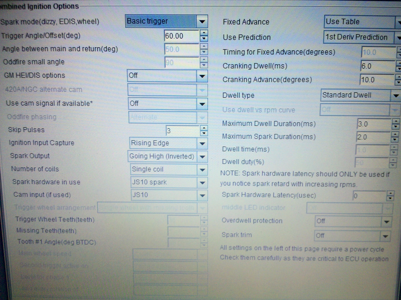
On my Tunerstudio it is under Ignition Setting then click Ignition Options/Wheel Decoder, and it is the first thing on the menu. Maybe with MS2 the settings are different, some one else who is running MS2 on the same firmware as you will have to chime in, but here is what my trigger settings are. I am basically running the engine on the same hardware as you, the stock CAS and the BIP373 for spark control, the only difference is in that I have MS3 on a V3.57 while you have MS2 on a V3.0. (These settings are not dialed in yet but the car is starting and idling at the moment) One nice thing about Tunerstudio is that under diagnostics (even in the free version!) you can log your trigger signal to really verify the working order of your CAS without doing the test procedure I described in an earlier post.

-
You should not have power to the coil when the key is off under any circumstance, it will melt your coil in short order. Your MS would only control power to the coil if it is hooked up to the fuel pump relay, which it is in your diagram. But when the key is off MS shouldn't have power either. So it seems like your wiring is a little messed up. What I did is leave the stock wires going to the + side of the coil, this means that the coil is only getting power with the key "on" and "start". I then have my pin #85 of both the fuel pump and main relay hooked up to the spade terminal from the + side of the coil, this means that MS only gets power when the coil has power, which is only when the key is "on" or "start". The main relays pin #86 goes to ground and the fuel pumps pin #86 goes to the MS so it can control it. I have pin #30 on both my fuel pump and main relays coming directly off of the + side of the battery,and pin #87 goes to my fusebox. Everything EFI related draws power from a common point this way, it simplifies things quite a bit. Like I said before, just make sure that the CAS or any thing else that should be on when the engine is off draws power from the main relay, not the fuel pump relay. As far as the jumper, that is only for the BIP373, that has nothing to do with your CAS. If you were getting an RPM indication but no spark, then it might be a problem with the BIP or the jumper, but for now you need to get an RPM indication from your CAS before you start worrying about getting spark. You will never get spark if the MS doesn't think the engine is running. For software settings you never mentioned what trigger scheme you selected. It should be basic trigger, and ignition capture should be set to rising edge. You dial in trigger offset by checking actual timing with a light and adjusting until MS matches the light, but ~60 degrees of offset seems to work good as an initial setting. (I have an MS3, so the offset might be different with yours).
-
Where do you have the +12V for the CAS wired into? If it comes off of any circuit coming from your fuel pump relay then it won't receive power until MS see's a TACH signal (which it won't because the fuel pump relay won't be on.) Also If the power to the CAS comes from any circuit attached to the STOCK Accesory relay it won't see any power during cranking, even though it will see power when the key is set to the "ON" position. I see that you have the + side of your coil wired into the fuel pump relay... I'm not really sure if that is a good way to do it since that means that the coil won't receive +12V until a TACH signal is attained.... might make for hard starting. I have my coil + side wired with the stock wires going to it and only the - side hooked to MS to control spark. To check your CAS I would think you could use the following procedure: 1. Remove distributor from the engine. (I would also remove the cap and rotor and the plug wires) 2. Remove the fuses to the fuel pumps and injectors ( so you don't flood the engine.) 3. Disconnect +12V from coil ( so you don't shock yourself or start fires from the arcing) 4. Turn key on 5. Take a voltmeter and attach the + lead to pin #24 of the DB37 connector and the - lead to a good ground. 6. Have an assistant spin the distributor by hand 7. You should see a change in voltage on pin #24 every time one of the six slots passes under the optical sensor ( assuming you have it wired correctly and it is a non-defective unit) 8. If not then I would assume you either have a faulty CAS or you didn't wire it right. 9. If it checked out good on this test then I would disconnect the "S" terminal of the starter and do the same procedure with the key on the crank position to make sure that it works while cranking too. EDIT: Actually since the DB37 will be disconnected from MS during this test is really shouldn't be neccesary to remove the fuses to the fuel pump(s) and injector or the wiring to the plus side of the coil. So if you want to you can ignore those steps.
-
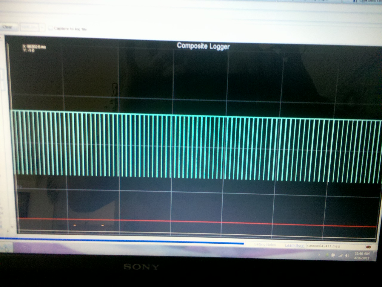
^^^ Great Recap^^^ Just for the record, it probably is possible to use the opto-isolated circuit if you adjust the pots correctly. They seem to be shipped with both pots set at the same level, if you were to turn R56 a few turns clockwise you might see a better signal. Using the VR circuit is working great for me though, so I would definitely recommend it. Here is what my composite log looks like now while idling: That looks a lot better lol. I don't know why my earlier log was showing a cam trigger as well... I don't have one. But anyway I'm glad we were able to figure this out. I need to get a driveshaft fabricated then I can move onto some more serious tuning. I will post my MSQ as soon as I feel like it is good.
-
This is the page that I read this on: http://www.msextra.com/doc/ms3/ignition.html#vrv357pull I'm happy to say that everything is working fine now, the car started right up after a few seconds of cranking and now I get to start the fun process of tuning!
-
How many feet of SS fuel lines would be adequate?
Cannonball89 replied to dpuma8's topic in Fuel Delivery
That "fuel accumulator" looks like nothing more than a remote oil filter adapter. -
Just checked my main board, it was configured for opto-isolated trigger. It needs to be configured for the VR+pullup trigger input. JP1 had a jumper between positions 2+3, I moved the jumper to positions 1+2 J1 had a jumper between positions 1+2, I moved the jumper to positions 3+4 I need to solder a 1K resistor onto the pads for R57 And I need to check the adjustment of the potentiometers on R52 and R56. I hope this solves the problem.
-
It's a V3.57, and actually, I haven't checked how it is configured. I obviously have a lot to learn still. I will check that tomorrow if I have time or saturday. It looks like the optical trigger setting is essentially the same as the VR input except for a pullup resistor needs to be soldered to the pads marked R57. This actually might be the whole problem. My advice, to anyone wanting to get a megasquirt, is learn to solder before you buy it and then assemble it yourself. It will give you a much deeper knowledge of how the board is configured and will save you the frustration of learning to solder anyway when you realize the preassembled kit that you paid more to get still needs to be soldered to add whatever extra goodies you need for your application. If I had it to do over again, I'd definitely be on a V3.0 board right now and would have assembled it myself. Thats a good thought too. None of my other sensors show any appreciable noise, so I would be surprised if that is the problem, but it can't hurt to experiment with that after I check the configuration of my board.
-
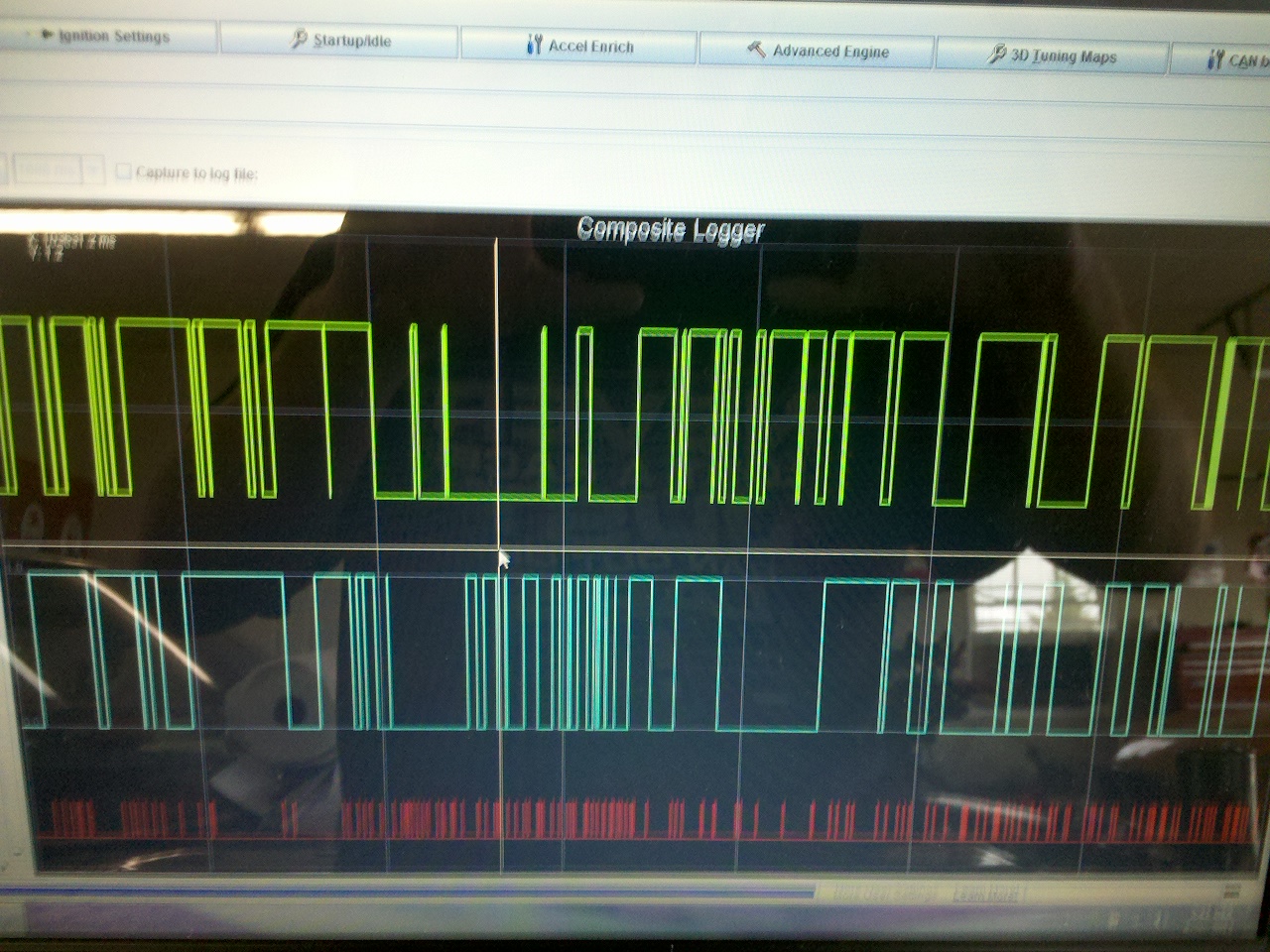
I am not trying to do EDIS or sequential spark, I'm just doing a basic set-up to get it running. Maybe fool around with the EDIS later. I am just trying to use the BIP373 to control my single coil and send the spark through the distributor. My problem is that I can't seem to get a good TACH signal and have yet to see an RPM indication. Here is a composite log of cranking that I just did, if it helps. Not sure what I'm looking at:
-
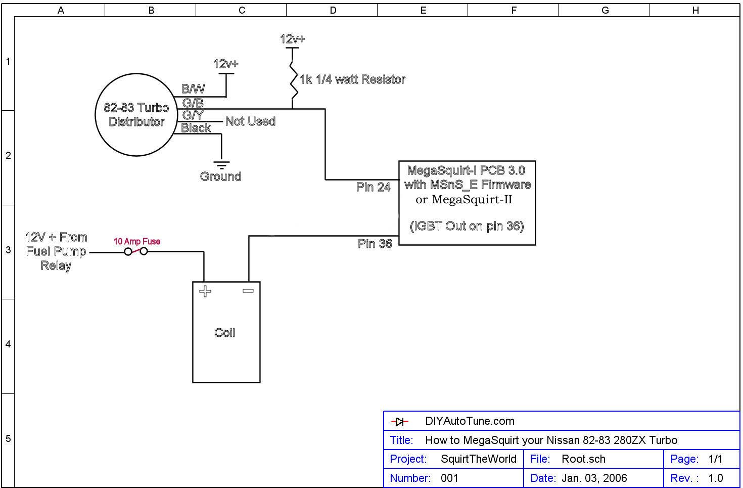
This is the diagram I followed when making my harness. The wire colors I stated are on the HARNESS side of the CAS. So for clarification, my voltage measurements were: B/W: 12VDC G/B: 5VDC G/Y: Not used Black: Ground If I understand what your saying correctly, then perhaps the G/B wire needs 12Volts instead of 5Volts? How exactly would I pull that up? With a different resistor?
-
Using the six teeth larger inner teeth instead of the 360 small outer teeth would make more sense for a basic trigger. I too haven't found any info on which ones MS reads. All of the posts I've read just tell you how to wire it up but don't go into any detail as to exactly how it works. I have no idea how to tell which set of teeth it is reading. My log shows no consistency at all in the signal. Pretty much what I would call a garbage signal. If I had to guess I would say that it reads both when working properly. I would think the log would show the six inner teeth as a taller bar and the 360 smaller teeth as a shorter bar. So basically what I would expect my log to look like would be one tall bar after every 60 short bars. But that is just a guess and it's not what I am seeing at all so far.
-
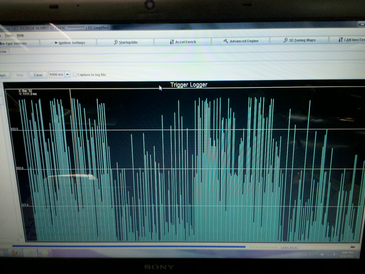
I have a 1971 240z with a 1983 L28ET. I am using the stock CAS in the dizzy for my tach input and have it wired up the way the way it says to in Moby's sticky and on the DIY page: http://www.diyautotune.com/tech_articles/how_to_megasquirt_your_280zx_turbo.htm I am using a BIP373 to drive the coil, and have hooked it up following the instructions here: http://www.diyautotune.com/tech_articles/using_bosch_bip373s_with_megasquirt.htm I have the V3.57 board and followed the instruction for single coil installations. I had some issues with fuel leaks and my fuel pressure being way too high, but I have resolved that and am now trying to get it running. I can't seem to get any RPM indication. When I turn the key on the MS3 powers on the fuel pumps for a couple seconds like it should, but when cranking the fuel pumps won't come on, I think that is because it is not seeing an RPM indication. I used the trigger logger feature in tunerstudio and this is what it shows when cranking: Here are my settings in tunerstudio for ignition capture: My trigger log looks pretty messed up to me. I don't think there is any way the computer could make any sense out of that signal. Does anyone know what the trigger log should look like with the 83 CAS?nI think that is likely the problem. I'm not sure if that is noise, or a defective CAS (the motor was running when pulled on the stock ECU, so I would assume that the CAS is not defective) I checked my voltage at the wires going to the CAS, the Green/White wire has ~12V, the Black/White wire has ~5V, and the Black wire is hooked up to the common grounding point on my engine block that I have all of my sensor wires grounded to. Another thing I'm not sure about is that possibly the MS3 firmware doesn't support this type of CAS yet. I've seen some threads on the MS forums that they are still working on support for Nissan 360 tooth CAS's. These threads seem to be talking about the KA24 CAS's though, I have found anything directly regarding the L28ET CAS. This is an interesting article on the MSextra site: http://www.msextra.com/doc/ms3/nissancas.html but I'm not sure if it really applies to the 1983 turbo CAS. I know it is optical and has a ring of 360 teeth, but I'm just not sure if it applies. I do have the V1.1 firmware. So I am going to do some more research and troubleshooting and keep you updated.
-
I'm also wondering about check valves, but on the return from the fuel rail more so than the return to the tank. I have a 5/16 line feeding the surge tank and a 5/16 return from the surge tank, and then I have a 3/8 feed to the injectors and a 3/8 return from the injectors to the surge tank... I am wondering if maybe fuel is wanting to flow up into my return line from the injectors into the bottom of my pressure regulator instead of into my 5/16 return to the tank... Perhaps this would explain why I can't adjust my Fuel pressure below 60PSI...
-
How to set up fuel and spark tables in tunerstudio?
Cannonball89 replied to Cannonball89's topic in MegaSquirt
Awesome thanks. I guess I will just use 250% because I have a 2.5 BAR MAP sensor. -
How to set up fuel and spark tables in tunerstudio?
Cannonball89 replied to Cannonball89's topic in MegaSquirt
Well I guess this is as close to a pioneer as I will ever be... I'd like to get the car idling sometime tonight (It's 2AM right now so I guess I mean less than 24 hours from now ) I think I will load the "MS3 example tune" that is included in the Tunerstudio software as a baseline, then set it to my engine parameters, and fine tune from there. I'm thinkin it will be close enough to get it started. The important thing will be to set my engine characteristics and injector characteristics, as well as my spark settings and ignition trigger methode correctly. These settings are close enough to Megatune that I think I can figure it out. Wish me luck -
Question About Surge Tank and Vapor Line Plumbing On 240z
Cannonball89 replied to Cannonball89's topic in Fuel Delivery
Ok I just drilled a small hole in the top of the tank and soldered in a peice of 5/16 brake line tubing for my return fitting. I'm running a peice of 5/16 rubber hose back to the tank from the surge tank for now, but will probably bend a peice of brake line tubing to serve as a more durable fuel hard line in the future for the run from the surge tank to the fuel tank. For vapor expansion/depletion compensation I have the one big fitting on the top of the tank going to the filler neck, and drilled a small hole in the top of the receiver for the gas cap, and also have an overflow tube going down to the ground just in case. Whenever I can find a regular tank locally I will probably redo the setup using the vapor recovery tank, and possibly put a sump on the bottom, but this will work for now. Thanks guys. -
Can someone explain to me how the AFR, VE, and IGN tables work in Tunerstudio? For the IGN table, instead of the Y axis being MAP as in Megatune, it is called IGNload%, so I'm a little confused as to what IGNload% is equal to. I thought it might just be a percentage of maximum MAP value, IE: I enter 250 KPA as my max MAP value, then 250 KPA would be 100%, 200 KPA would be 75% etc, but it seems that most people have been using 400% as the max IGNload% value. Why would percentages be used instead of the simple MAP Y axis that megatune uses? And what exactly does it mean? The AFR and VE tables are set up similarly but it seems that 100% AFRload% and 100% VEload% are the max values for those tables. I can't seem to find any information in the Megamanuals or EFIanalytics website explaining this. This is a bit of a problem for me, because I have MS3, and am therefore only able to use Tunerstudio, I can't set up Megatune initially then figure out Tunerstudio as I go. I pretty much am trying to make my own tune from scratch because I can't find an MSQ for MS3 for the L28ET yet. The problem is that when trying to copy data from the sticky http://forums.hybridz.org/index.php/topic/34536-megasquirt-map-information-sharing-all-code-versions/ into my tables, my Y axis is different than the ones in that thread because they are all from Megatune. So please help me figure this out, thanks.
-
It probably says "JECS" not "JEGS"
-
Question About Surge Tank and Vapor Line Plumbing On 240z
Cannonball89 replied to Cannonball89's topic in Fuel Delivery
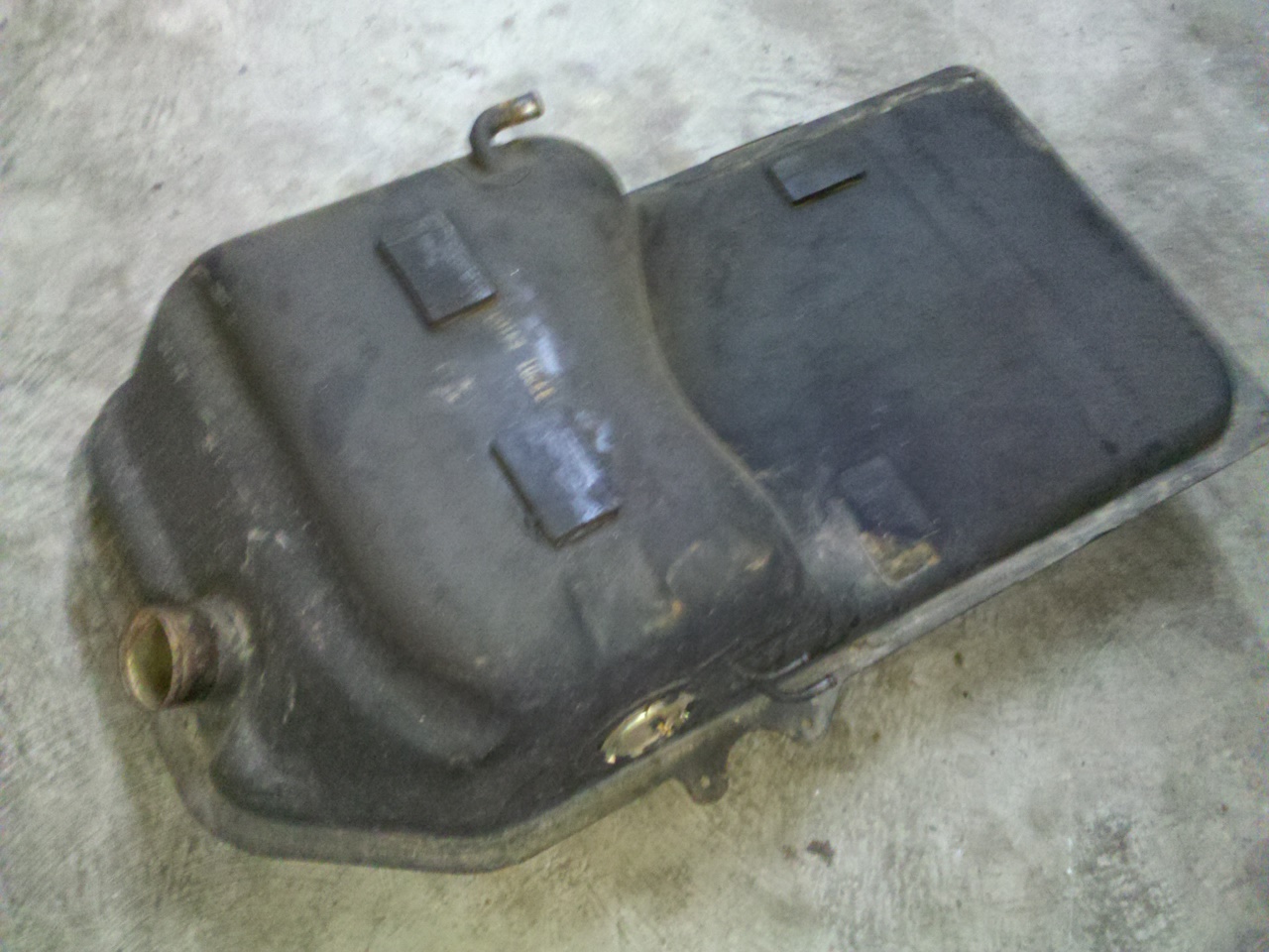
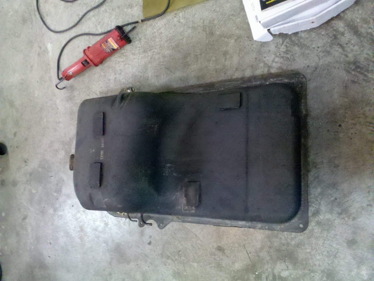
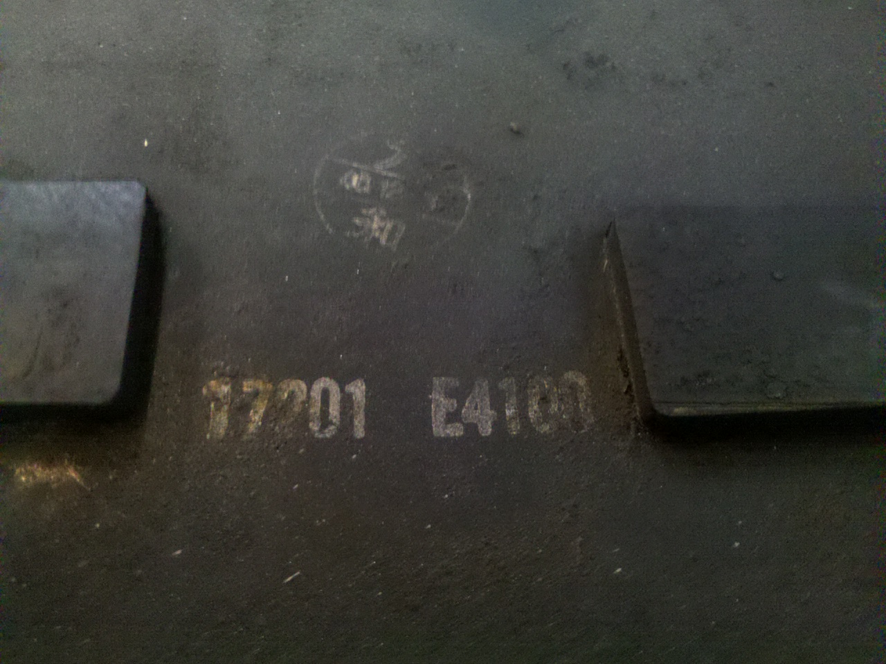
Ok I dropped the tank and took some pictures. I've read about tanks like these but never seen pictures... Perhaps a HybridZ first? I doubt it but I couldn't find anything with searching. I did find some spirited debate between Mr. Jmortenson and Mr. Tony D debating the merits of eliminating the vapor tank. Coincedently these are the only two individuals who have replied to this post lol. I'd also like to change the title of this post, since it has veered substantially off of it's original title, but it doesn't seem to let me edit the original post. So here is what a non-emissions tank looks like Markings on the top read 17201-E4100, and I can't make out the circular marking.
-
Question About Surge Tank and Vapor Line Plumbing On 240z
Cannonball89 replied to Cannonball89's topic in Fuel Delivery
The feed and return lines are 5/16" and 3/16", respectively, just like any other 240z. I mistakenly called the return 1/4" in an earlier post but it is 3/16". I am going to drop the tank later tonight and take some pictures of the whole thing. I ran across this thread from another site where someone found a tank that sounds just like mine: http://www.classiczcars.com/forums/showthread.php?t=39219 My plan right now is to route the solitary vent hose on the tank to the filler neck, and run a ventilated gas cap like the 1969 240z's allegedly had. Anybody know where to buy a ventilated cap for a 240z? I hate to just drill a hole in my gas cap, it just seems wrong. For the return to the tank, I'm thinking now about putting a fitting on the filler neck itself for the return line instead of putting it on the tank. I would put the return line fitting on the portion of the filler neck in the rear tire well, not the portion that runs inside the car. I think that would serve the same function without messing up a potentially rare gas tank. -
Question About Surge Tank and Vapor Line Plumbing On 240z
Cannonball89 replied to Cannonball89's topic in Fuel Delivery
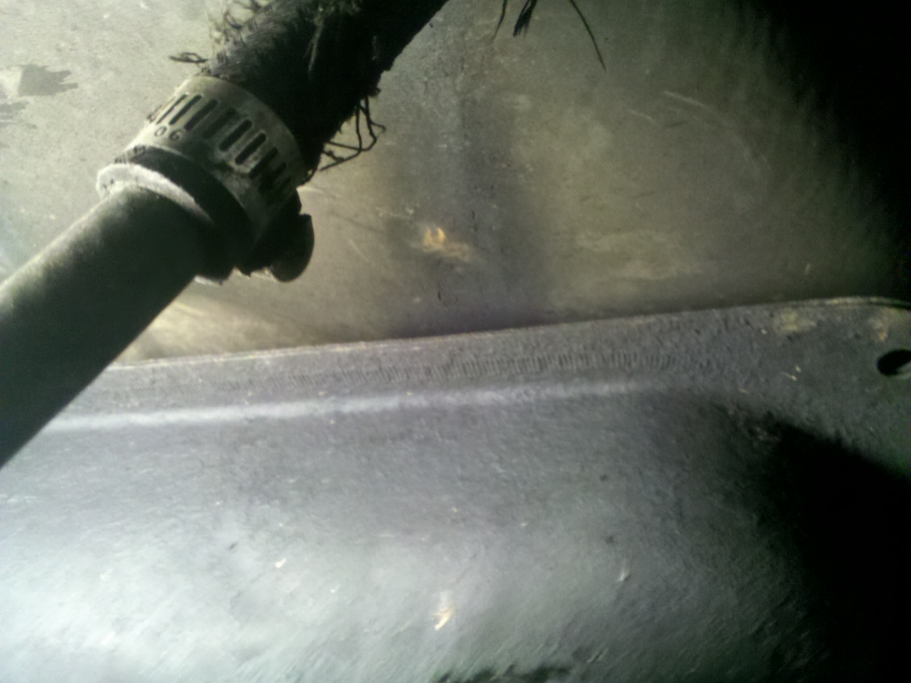
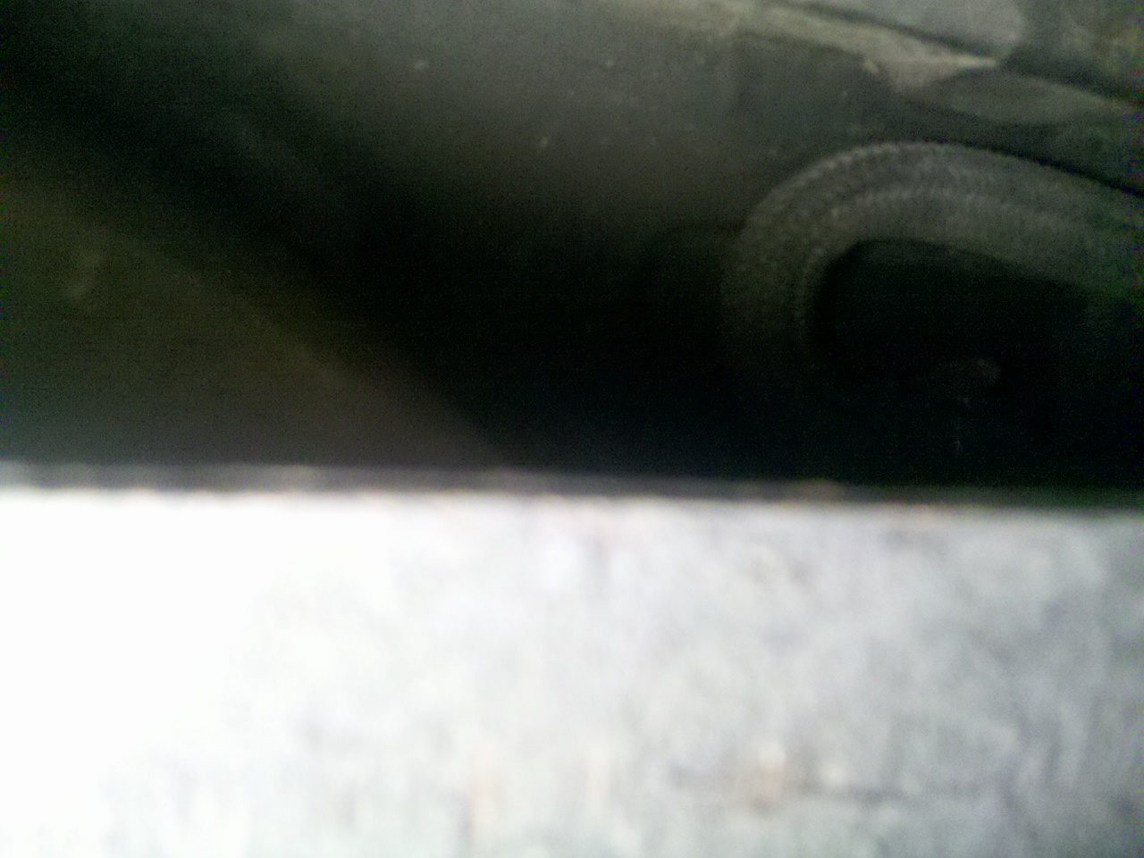
Well I've got an interesting development in my 240z... it turns out I have a NON-EMISSIONS GAS TANK! WTF!!! My car was built in 3/71, so it obviously was an emission compliant model, and all of the stock emissions components were in place, such as the vapor tank, flow guide valve, all of the balance tube mounted gizmos, but some one at some point had swapped the tank for what must be a VERY early U.S. Z tank or perhaps a Canadian, Euro, or JDM tank. The thing is that now looking at all of the lines running to the vapor tank, I'm pretty sure they were hodge-podged together by one of the idiot PO's. Basically the only vent line I have on the tank is the one on the very top, toward the rear. The one on the very top towards the front and the one of the drivers side under the spare tire well is not there. So someone took the two lines coming down through the floor boards from the vapor tank and basically ran them together, making a loop. The fact that I never noticed any raw fuel smell was a miracle, and come to think of it this would probably explain why I would intermittently have the car sputter cruising down the highway, and also intermittently have hissing coming from the gas cap area until I opened the cap for a moment. What gets me is that I should have known about this over a year ago when I had the tank out of the car and had it proffesionaly cleaned by a radiator shop to remove a mouse nest (no lie) that was preventing me from getting more than a block away from my house before the fuel filter got clogged with mouse nest material, or whatever you would call that fluffy stuff. I was such a total noob that I never even bothered to look at how the lines from the vapor tank were routed. I just hooked it back up the way it was and never thought about it again lol. So anyway my plan for now is to remove the vapor tank, and run it as if it were a pre-emission model, and I guess I will have to have the tank tapped for a larger return line. I hate to do that because this tank might be valuable to someone restoring a very early Z or some other non emissions Z. I hope to someday find a regular 240z tank or even better a 75-76 280z tank and swap it in place of mine so I can run the vapor tank and stock evap system, then sell this tank to someone who might appreciate it more, but for now ventilated gas cap appears to be my only option. Here are some pictures to prove this insanity This is where one of the vents should be, above the sending unit. You can see that the stock hose is there, but is the vent there... nope This is on the drivers side below the spare tire well, again you can see the stock hose is there but is there a vent... nope. The hose you see shoddily stuck inside of it is what was connected to the hose in the above picture. And here is the only vent I have on the tank, the one that's in the rear and is almost impossible to see, let alone reach without dropping the tank.
-
I think the primary goal of save the ring is to make the racetracks at the Nurburgring a separate entity from the amusement park. I don't see anywhere on that site where they are asking for money from anyone, they just want to ensure that the racetracks are owned by people who understand motorsports and won't close the tracks down or something. And I guess there is risk that the German government might close the tracks down too if they take possession, I mean think about it, would the U.S. Government really sanction a place like that? It seems that if the government controls it then it's just a matter of time until some environmental special interest group manages to get it shut down. That is just my speculation though, I don't know anymore than you do.
-
That is where the Australian Grand Prix should be held. What an awesome track. That's another thing that pisses me off about F1 today is that most of the tracks are totally devoid of character. With the exception of Monaco, Spa Francorchamps, Suzuka, and Monza (although even Monza is watered down compared to how it was in the 60's) the tracks are basically cookie cutter circuits that are mostly flat, wide, and devoid of any real high speed or technical sectors. I say bring back the Nordschleiffe! Oh and by the way, the Nordschleiffe is at serious risk of closing down. Check this out: http://savethering.org/
-
Making more than 1000HP per liter from an engine is not that big of an accomplishment... Making that engine last more than a 1/4 mile is!!!
-
I agree that instituting a gallon per hour or miles per gallon rule would be a good idea. I believe that Le Mans prototypes have such a rule in place, or at least they used to. Racing does need to have some relevance to street cars in order for manufacturers to be involved. For example, instead of using Kinetic Energy Recovery as a short burst of power on the straightaways, it could be used as a slow trickle of power to reduce fuel consumption throughout the race. If the FIA were to make the fuel consumption limit strict enough I believe many teams would use KERS in that fashion. The FIA has moved slightly in that direction this season as refueling during pit stops is no longer permitted. I think it would be cool to see some diversification of engine technology too. Instead of everyone running 2.4L V8's (or 1.6L turbo 4's in 2013) it would be great to see some Wankels, Diesels, maybe even some sort of jet propulsion, who knows. I'm too young to remember the 60's, 70's, or even the 80's, but reading and watching film about F1 development during those days is mind boggling. Not just F1 but also CAN AM, Group B rally, even NASCAR. I just want to see very little interference from the FIA and other sanctioning bodies with regards to the mechanical aspects of the cars, that is when the really wild development takes place, and the best racing too. Sure one team will be ahead of everyone for a while, but eventually some one else will catch up. That's what competition is. Competition is not handicaps and push-button passing-power.