Cannonball89
-
Posts
224 -
Joined
-
Last visited
Content Type
Profiles
Forums
Blogs
Events
Gallery
Downloads
Store
Everything posted by Cannonball89
-
I just watched the first ten laps of the Grand Prix in Australia, and I gotta tell you I am so pissed off that they have made it so complicated. Talk about "manufactured excitement". I stopped watching NASCAR after they introduced the "chase" formatting to the points system because I saw it as a way to artificially make the championship more exciting. Now in Formula 1, they are doing the same thing but instead of messing with the points system, they have installed elaborate systems onto the cars themselves to artificially make the racing closer. I heard that they would have adjustable rear wings this year, and thought, "ok, there giving the teams a little more room to work with the rulebook" But no. They have actually made it so that if you are 1 second or less behind the car in front of you, only then can the driver activate the wing control. Talk about stupid and arbitrary manipulation of the competition. Whats wrong with making the drivers race like men and let the fast guys win? And this KERS system is the dumbest thing I've ever seen. It basically lets the driver push a button and get something like 80 extra horsepower. I mean thats just not racing when you can push a button and get a ~10% gain in horsepower. I can't wait until NASCAR and the FIA go bankrupt and we can start from scratch again with premiere racing leagues. Racing is plenty exciting without all this "manufactured excitement" BS.
-
Question About Surge Tank and Vapor Line Plumbing On 240z
Cannonball89 replied to Cannonball89's topic in Fuel Delivery
I understand your concerns about location, but the surge tank is made from fairly thick aluminum, so I don't think the odds of it puncturing during an accident are very high. The risk of fire from having fuel sitting in the surge tank is in my eyes at least, no more so than the risk of fire from having fuel sitting in the float bowls of the carburetors. But the location of the surge tank is really just personal preference. As far as having a smaller pump, just because the surge tank is only holding a small amount of fuel doesn't mean it only needs a tiny pump, the point is to make sure the surge tank never gets air in it, so the larger the pump feeding it the better. There also shouldn't be any pressure in the surge tank from using a 5/16" feed and 5/16" return, there would only be pressure in the surge tank if the return were smaller than the inlet. Thanks for pointing out that the line to the engine compartment goes to the vapor tank in the rear of the car, not directly to the gas tank. For some reason I thought that it came from the top of the gas tank. Looking at my FSM I see that now. I wanted to keep the stock vapor tank system in place, because I have never smelled raw fuel from my car and would like to keep it that way, but I see that many people have removed it and run a ventilated gas cap. I suppose that would be an option. I just hate messing with factory the factory evap system. My racecar has a simple vent on the fuel cell that goes directly to the atmosphere, and it makes my trailer smell like raw gas on hot days. Another problem with using the stock ventilation system is that I don't know how the system will respond to boost, IE positive pressure instead of vacuum or atmospheric pressure on the flow guide valve. I'm still brainstorming how I want to run my return line. I guess I should either remove the vapor tank and have a simpler tank ventilation system, then use the 5/16" line as a return, routing it to the tank, or I could run a new line to the gas tank and drill and tap it with a fitting, and keep the stock ventilation system in place, provided that boost will not affect it's operation. I have to do some more research on how boost will effect the system. Any other suggestion are welcome. -
Here is what I have, I have a 140 GPH low pressure carburetor style fuel pump in the rear of the car that will pump fuel through the stock 5/16" hard line to the engine bay, which will then feed into a surge tank. The surge tank has a 3/8" outlet on the bottom to gravity feed a 70 GPH high pressure FI pump that will supply fuel to the my fuel rail, through the FPR, then back into the surge tank. My question is mainly regarding the return to the tank. I know from reading that the stock 1/4" return line is inadequate, and one option some have suggested is to use the 5/16" hard line that is a vapor line in stock configuration and use it as the return. If I do so, what do I need to do for my vapor system? In stock configuration the vapors went through a valve that either let them go into the crankcase or into the aircleaner box. I'm sure I will have problems if I simply use this vapor line as a return and do nothing in exchange for the vapor system. Could I use the stock 1/4" fuel return and route it to the vapor valve so it functions as what the 5/16" vapor line was doing? I know some of you have used that vapor line for a return on your surge tank set-ups, I just haven't been able to find what you have done to modify the vapor system in exchange. I suppose another option would be not to have a return to the tank, and allow the 140 GPH pump pump into the surge tank without a return... maybe... Please advise. Thanks.
-
You don't know what your talking about. 240z only has one fusible link which was rated at 80 amps. There is no headight fusible link on a 240z. Just one. The setup I describe is safer than stock because instead of a wire that is designed to slowly burn at 80 amps I have a fast acting sealed fuse. The headlights, brakelights, and everything else are seperately fused through the stock fusebox. Any short in those seperate circuits will blow that respective circuits fuse before it blows the 80 amp fuse I installed, which is only a fail safe as it is main circuit protection. No offense you just need to know what your talking about before you condemn a set up that mirrors how the factory did it with the exception of more modern components.
-
If you have MS and are running big fuel pumps it shouldn't affect the main power wire, you should have all of the fuel injection stuff on a separate circuit that is separately fused. I am running another ten gauge wire to the + post of the starter motor next to the main power wire to draw power for all of my fuel injection stuff. If you are drawing power for MS through the main power wire then I don't think you have it wired correctly, and that may cause issues with too much amperage through the main wire and also likely introduce a lot of noise to the MS. EDIT: Disregard this post, I know now that everything will travel through the main power wire through the alternator. I stand corrected.
-
Install a fuse inline in that wire. I bought a big 80 amp fuse and holder from the local parts store, It was a bussman I believe. I ditched the fusible link and ran a wire straight from the + side of the starter motor into the fuse box, then from the fuse box to the white 10 gauge main wire. I have a 105 amp alternator and have had no problems with it. The only way you could really have a massive power surge through that wire is if your alternator shorts internally or some other short occurs in that main wire, your headlights, wiper motor, and brake lights, etc, don't really draw that much current. If you do have a power surge, that fuse will fail before anything bad happens, and before your white white/red wire has a chance to melt or catch fire. That fuse box is a great anti-theft device too. Just pop that fuse out when you have to leave your car somewhere seedy and there's very little chance a thief would be able to figure it out. It will cut power to everything.
-
Strap the laptop securely under your seat and don't tell the SCCA its there? Its kinda hard to say where the problem is coming from without data. Could be ur boost control solenoid creating interference at high duty cycles not seen on the street or something like that. Or it could be that MS reset on track under boost. I've heard that when MS resets the MAP sensor reads whatever pressure it is seeing as atmospheric, meaning that if you reset at full boost it would see 3 PSI as vacuum.
-
Coolest way to get down a european alpine pass?
Cannonball89 replied to Two80z4me's topic in Non Tech Board
I think I'd have more fun going down that in my 240z. Just my opinion though. -
I can answer one of your questions, the difference between open and closed element IAT sensors is simply that the closed element sensor has the actual sensor enclosed in a copper jacket, while the open element sensor is exposed. The closed element sensor is really for use as a coolant temperature sensor as water will not damage it, while the open element sensor is better for intake air temperature because it is more sensitive and will have less "lag time" between when ambient air temperature rises or falls and when the sensor can read it. You can use the closed element sensor for both coolant and intake though for NA cars, because intake temperatures do not change very rapidly. Turbos really need the open element sensor though. I can also say that MS II is a great choice. MSIII is based on MSII and you could upgrade your MSII to an MSIII later if you ever wanted sequential injection or any of the other spare outputs and inputs.
-
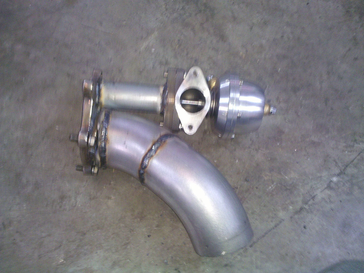
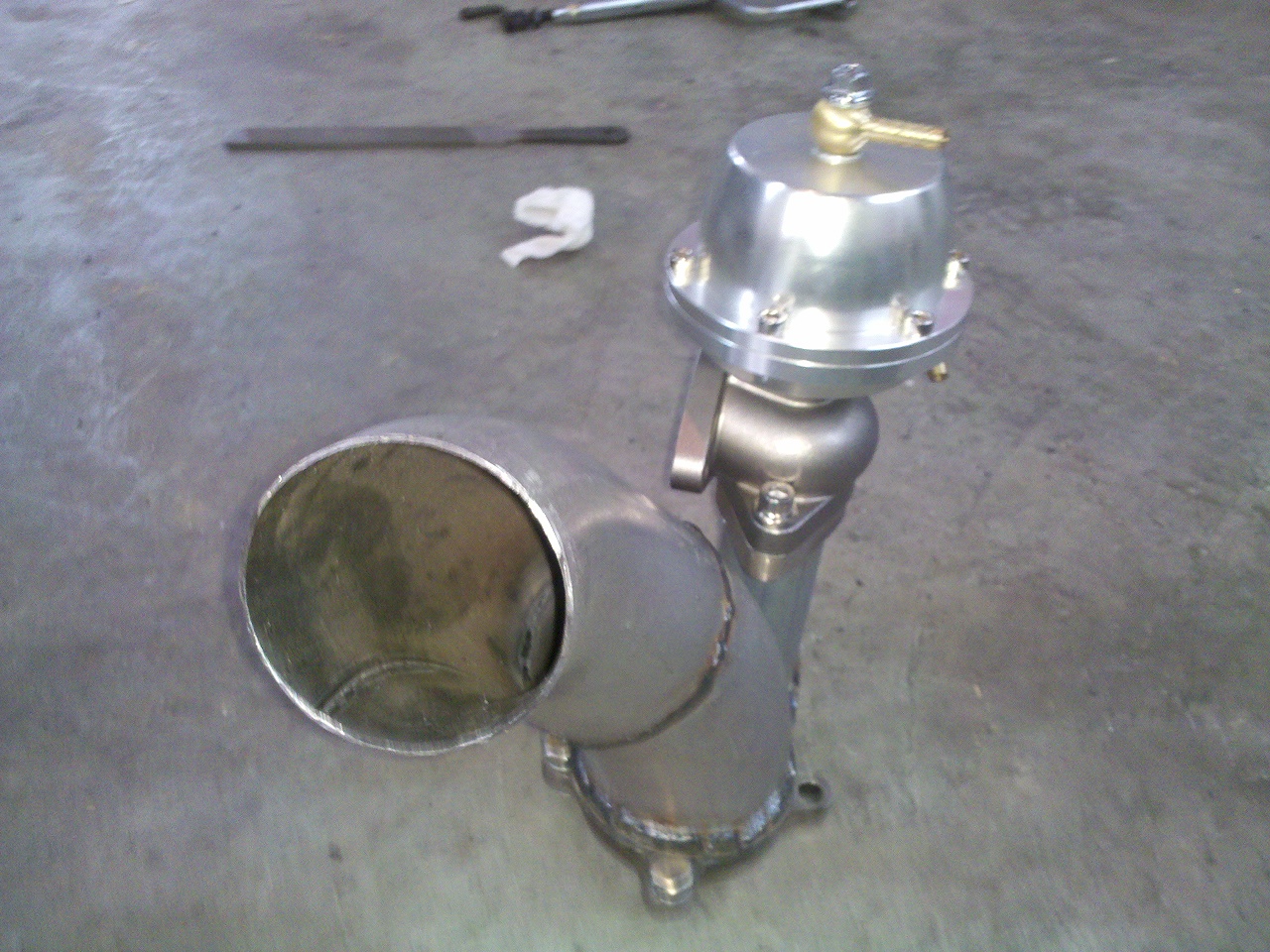
3" Downpipe, 38MM Divorced Port Wastegate
Cannonball89 replied to Cannonball89's topic in Turbo / Supercharger
I think it will perform in between a stock internal gate and a wastegate mounted directly to the manifold. The stock gate creates turbulence right after the turbine that robs power under boost. This set up will vent wasted exhaust gases either directly to the atmosphere or into the main exhaust pipe further downstream where turbulence is not as harmful (I haven't decided yet). So it will produce more horsepower than the stock internal gate. I also believe it will be less prone to boost creep than stock internal gate due to the less restrictive path that the wasted gases travel, but I don't believe it will be as effecient at controlling boost as the wastegates that are welded onto the manifold because I am using the small hole that internal gates use. Basically it's a trade-off. Once the car is back on the road we will find out for sure how effective it is. -
Assuming that you have an S30, I think a 16" height will be a little tall. You'd have to cut out the a portion of the front valence and have part of it sticking below to clear the hood.
-
Well my turbo swap for my 71 is taking longer than I planned, mostly because I can't resist the urge to go overkill and fabricate stuff like this. Uses an exducer purchased from D&W Diesel Performance to expand the diameter from the 2.5" turbo (T3/T04E) outlet to 3" for the downpipe. Wastegate is a copy of a Tial 38MM from SSAutochrome. It was cheap and don't know if it will be reliable but I can always just bolt a Tial on later. Piping is 3" mandrel bent mild steel. Screamer pipe will be 1.5" mandrel bent steel. I haven't ported the turbine housing so 38MM is WAY bigger than I need but if I get creep it will be relatively easy to port the turbine, no modification to the downpipe and flange will be needed. You don't see a lot of divorced port wastegate set-ups, probably because they are more prone to creep than the external wastegates mounted to the manifold, but we will see how this works for me soon. If nothing else it looks cool.

-
Super High Output 4G63 (link to thread, not mine!)
Cannonball89 replied to Canadianz's topic in Other Engines
Thats approaching the level of development that went into the turbo F1 cars. I believe the BMW team claimed something like 1500 HP from the 1.5L four cylinder in qualifying trim. Race trim was a little less. So 2000 HP from a 2L is not unbelievable. The question is, would this motor survive a 90 minute grand prix? or is it something that has to be rebuilt after every few passes down the dragstrip. -
Need help with gland nut...
Cannonball89 replied to Josh280z's topic in Brakes, Wheels, Suspension and Chassis
I took mine to a welder who used an acetylene torch to heat it. They came off easily with that. I tried propane but it just isn't hot enough. -
My 1983 turbo ZX did NOT have dropping resistors. I'm not sure if that was an 83 only thing or a turbo only thing but there were not dropping resistors on 1983 turbo ZX's.
-
Thanks Moby, and yea that would be sweet to have something mounted in the glovebox to allow you to tune without a laptop. I bet one of those new tablets would fit nicely, like an Ipad or Android tablet... Hmmmmmmm if only I had unlimited time and resources lol
-
Here is the diagram focusing only on the glove box unit
-
Here is my wiring diagram for the whole EFI system. I should also note that I am using a 240sx TPS. Please look over it and let me know if you see any problems. One thing I'm not 100% sure about is the way that the 1K 1/4 watt resistor hooks up to the TACH signal.
-
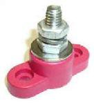
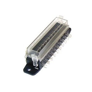
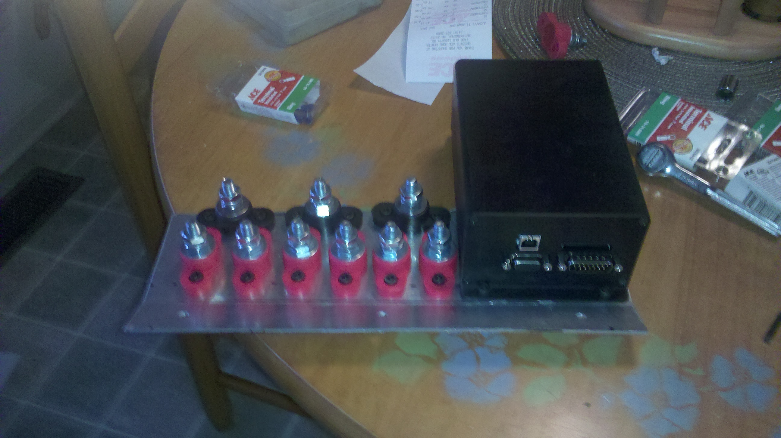
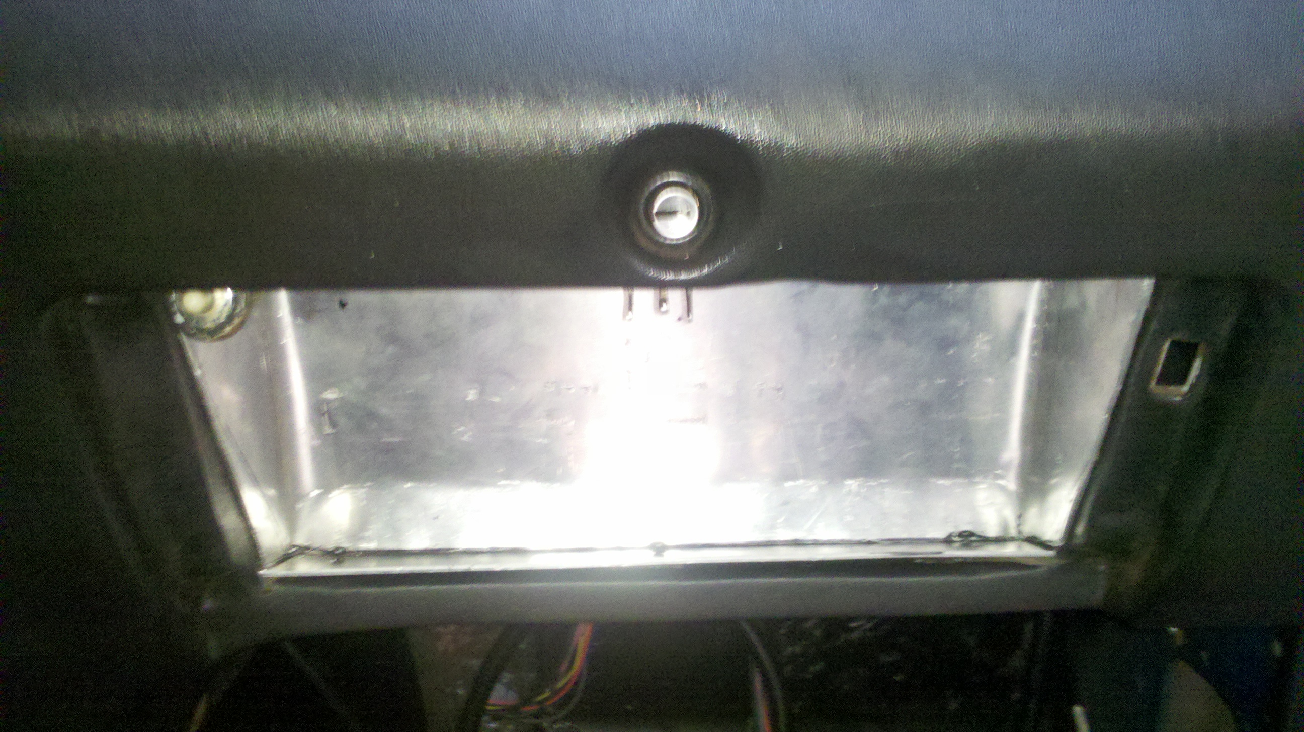
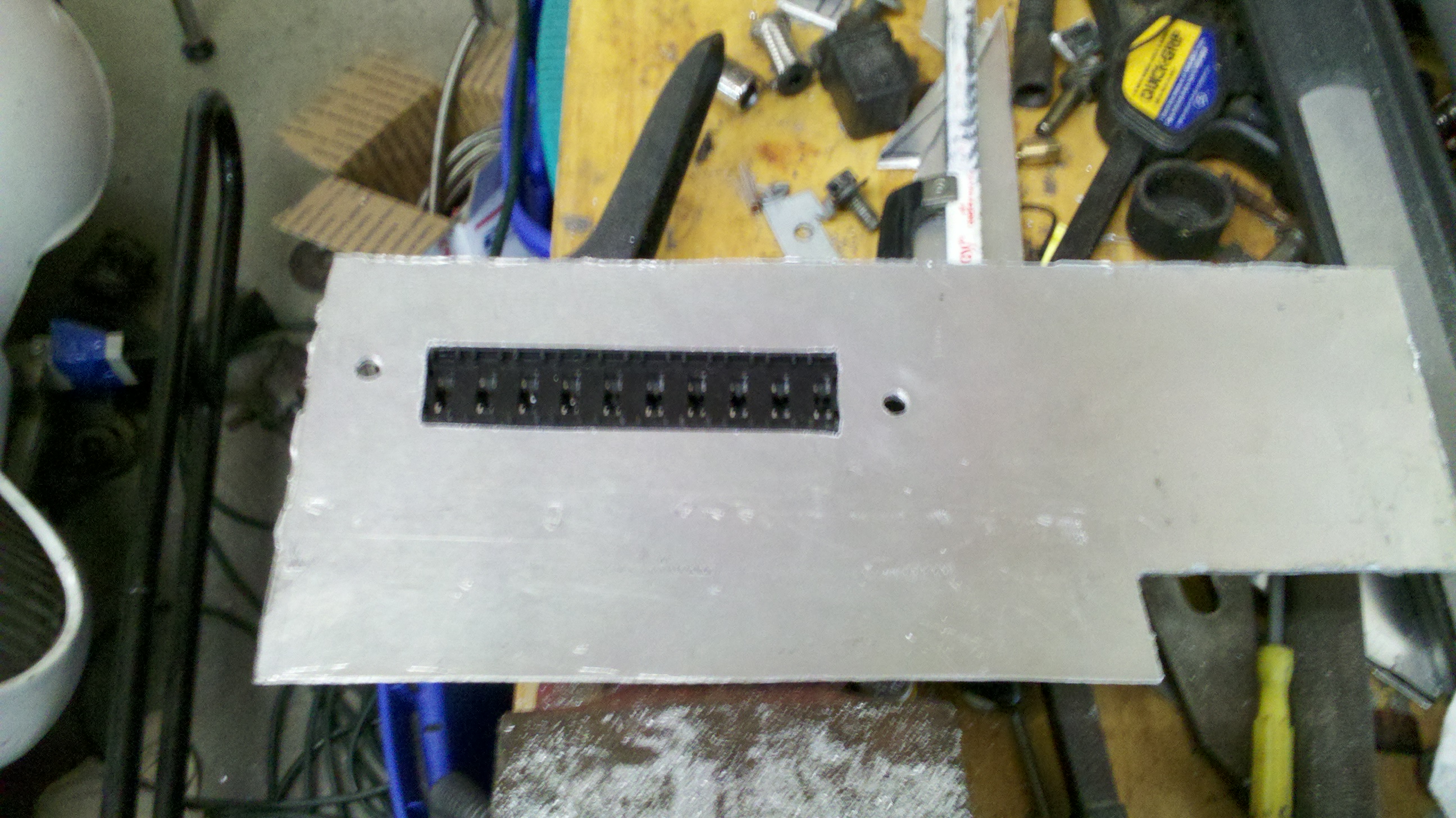
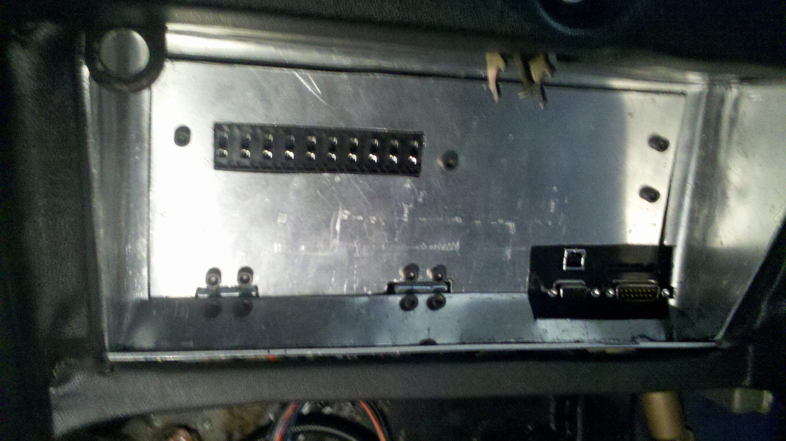
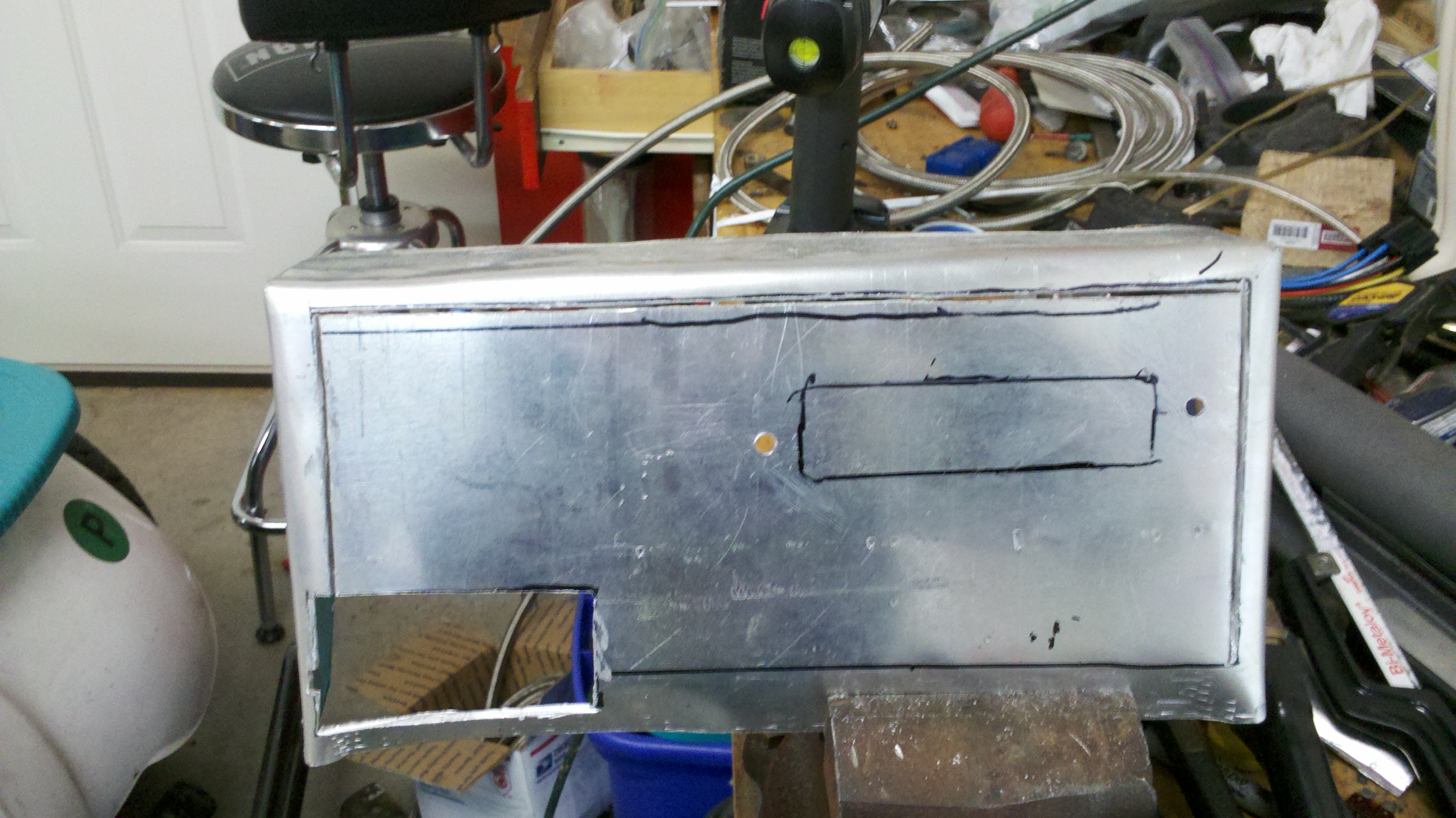
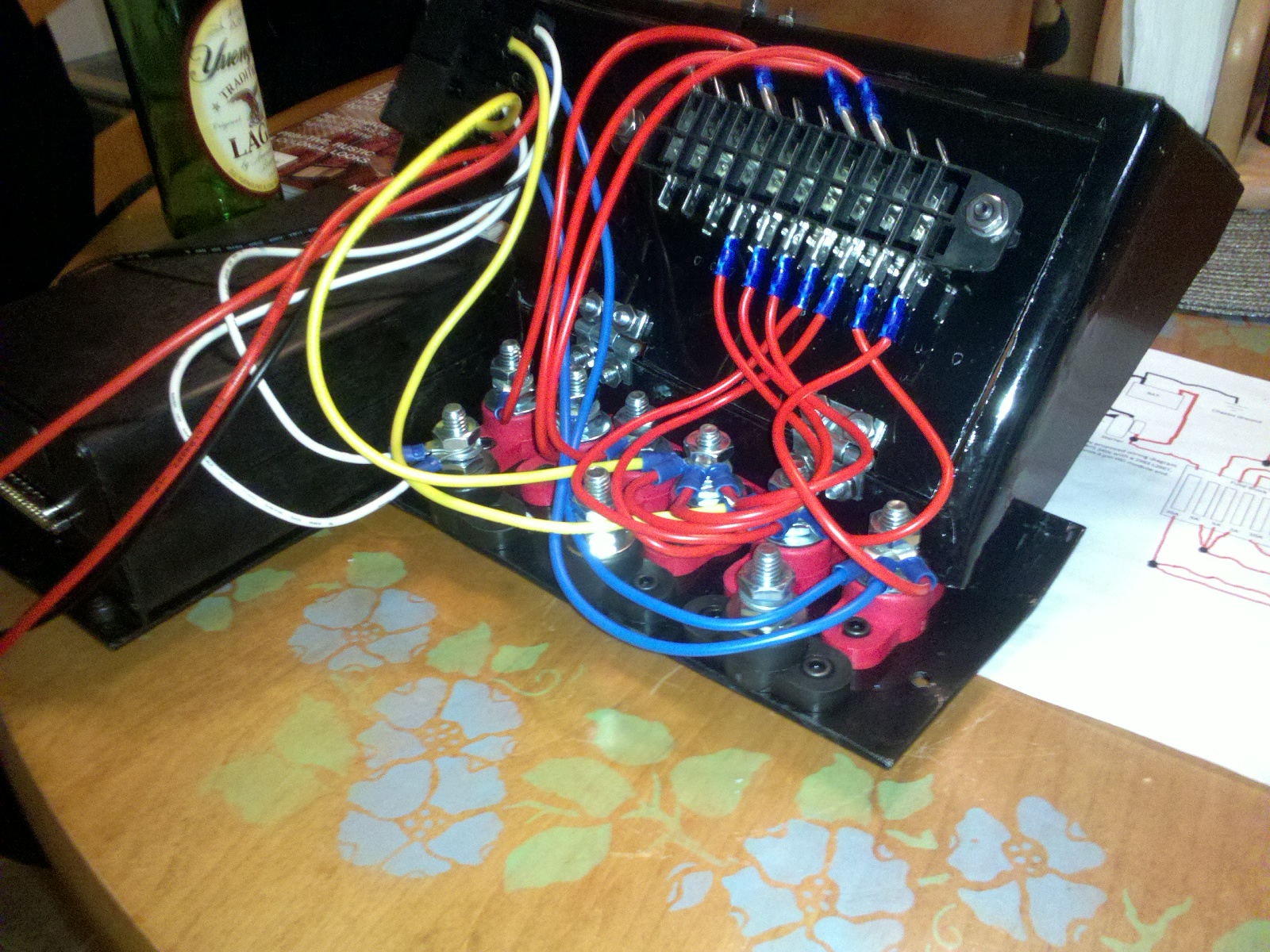
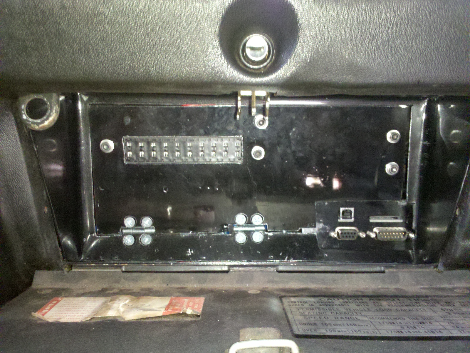
So I've been working on putting an L28ET with megasquirt into my 1971 240z over this winter. One of the things I don't like is the unfinished look of the relay board, and also the limited options for fused circuits incorporated into it. For example, I have two fuel pumps I want seperately fused, and with the relay board you can only have one fuse for a fuel pump. I'm also not a fan of the screw terminals on the relay board, I just don't think they are the most reliable connection. Basically I wanted something that is out of site yet easily accessible and easy to work on, that looks professional. Since my car has just had a big hole in the dash where the glovebox should be since the day I bought it, I figured I might as well utilize that space for the MS, fusebox, and relays. I thought there would be gobs of room, but once I placed the blower motor in place, I realized it is actually pretty tight in there, but it all fits. It's snug but it does work. So here's kind of a walkthough of how I fabricated all of this and what parts I used. I haven't really seen anybody else do anything like this, but I'm sure someone has. First off, some kind of power distribution blocks are needed to use MS without the relay board. I used these 5/16 stud type blocks, available here: http://www.carshopinc.com/product_info.php/products_id/120620/406-205 Next I wanted at least seven seperately fused circuits, but bought a ten circuit block so I had room to add additional goodies down the road. I looked at painless wiring products but they are way too expensive. I found these on amazon for ten bucks not bad. http://www.amazon.com/10-section-ATM-Automotive-Fuse-Block/dp/B0023TIAEO/ref=sr_1_5?s=automotive&ie=UTF8&qid=1299371748&sr=1-5 Thats really the only specialty products I used, the rest of a couple sheets of 1/8" aluminum, lots of fasteners, and lots of wires and fasteners. The first thing was make a base plate that the MS and the power distribution blocks will sit on. This is just a flat plate that has a slight bend in it towards the front to follow the profile of the dash. It has to be shaped that way to clear the blower motor and the duct that comes down for the defroster. Here I mounted to MS and the blocks. Here comes the hard part, making a piece to fill in the rest of the glovebox. I made this from a single sheet. This piece was VERY hard to make. I don't have a lot of tools, I just used a pnuematic cut off wheel to cut the shape then used a vice to help me bend it. I took many many hours of trail fitting and messing around before I got it to fit right. If I ever do something like this again, I think I will try to use fiberglass or something other than metal to make a piece like this. Now I'm not done with that piece, it has to hold the relays and fusebox, and provide easy access to the MS and the wiring. So... It needs to be cut some more to make a door on the front of it that is hinged to allow it to fold down and also have a cut out to have access to the front of MS for the USB and SD card slot. Then a rectangular hole needs to be cut out to allow the front of the fuse box to stick out so you have access to the fuses. Now I just got some small door hinges from the hardware store to allow the access panel to fold down. Here is the unit mocked up and put in place. I simply welded a small nut onto a piece of steel to hold the door up when it is closed. Next up is some black paint to make it a little more incognito. I used Eastwoods chassis black. I kinda wish I had used a matte finish instead of gloss, but your only going to see it when the glove box is open so I guess it doesn't really matter. Now for the fun part... reassembly and WIRING! It's really not as complicated as it looks if your not familiar with megasquirt. I probably made it a little more complicated than it has to be. This is my first time wiring a megasquirt. I don't want to discourage any newbie from buying a megasquirt because of the amount of wires. I will post a schematic of the wiring as soon as I have time to make one so you can all see the method behind my madness and possibly catch any mistakes I might have made. Now I finally got the unit installed today and am able to start wiring the rest of the MS harness. I have bought the pre made 12' harness from DIY autotune. Overall I am very happy with how it turned out. It just took a long time and was a lot more work than I had invisioned lol but thats how most of my projects turn out. I will update with my wiring diagram and my progress later. Thanks for reading, Matt
-
It's all good Mario, we all have our moments. Looking back at some of my early posts on Zcar.com I wonder what the hell I was thinking... Then realize I wasnt't lol, I was either too drunk or tired.
-
Yea, cold pipe is definitely not running behind the radiator lol.
-
Mystery Battery Drain in 1976 280Z
Cannonball89 replied to PhilbertZ's topic in S30 Series - 240z, 260z, 280z
Or buy one of the Zmans 105 or 125 amp alternators. I bought the 105 amp and it totally eliminates the "brown out" at idle. -
I just mocked up my intercooler piping today. I got the aluminum pipe and couplers from http://www.siliconeintakes.com/ I have a cheap ebay T3/T04E and the piping is 2" off the turbo then necks up to 2.5" at the intercooler then into the throttle body. I just need to order a 2.75" to 2.5" adapter now for the throttle body because I didn't realize my 240sx throttle body is a little bigger than 2.5" I need to order some 3" stuff for the intake into the turbo too and a nice K&N filter, then once the fuel lines and surge tank are mounted, the megasquirt wired up, and the exhaust and wastegate welded up this baby will be on the road again! (Oh yea and a custom driveshaft) This shiny new motor is going to make my old faded paint look even worse! I got this trick BOV coupler from silicone intakes too. Pointing down is the only way I could get the Type RFL BOV to fit. This saved me from having to buy the equipment to weld aluminum or pay someone to do it. It's gonna be pretty tight between the fan and the motor. I think there is enough clearance though. Once I tighten the clamps I can get about 1/4" clearance on each side of the pipe. I might rigidly mount this pipe to the motor if there is any problem with it hitting the fan.
-
Mystery Battery Drain in 1976 280Z
Cannonball89 replied to PhilbertZ's topic in S30 Series - 240z, 260z, 280z
I had my alternator fail at the Import Nationals at Carlisle last year. It created a short circuit so bad it vaporized my fusible link (like its supposed to do). When I took the alternator off I could hear something rattling around in it. It turned out that the diodes had broken off and fallen down inside the alternator housing creating a massive high amp short. Alternator would definatly be the easiest thing to check at this point. Instead of replacing the fusible link I installed an 80 amp fusebox. A little safer and cleaner than having a wire catch fire under the hood IMO. -
Thanks for the quick responses guys. I knew there wouldn't be "cheap" or "easy" solution for this. So I guess I'll be talking to my driveshaft shop about what my options are. Thanks. Expect a thread soon showing everything I've done for my build. Its pretty basic but I can't help but show off... he he