Cannonball89
-
Posts
224 -
Joined
-
Last visited
Content Type
Profiles
Forums
Blogs
Events
Gallery
Downloads
Store
Everything posted by Cannonball89
-
3" Downpipe, 38MM Divorced Port Wastegate
Cannonball89 replied to Cannonball89's topic in Turbo / Supercharger
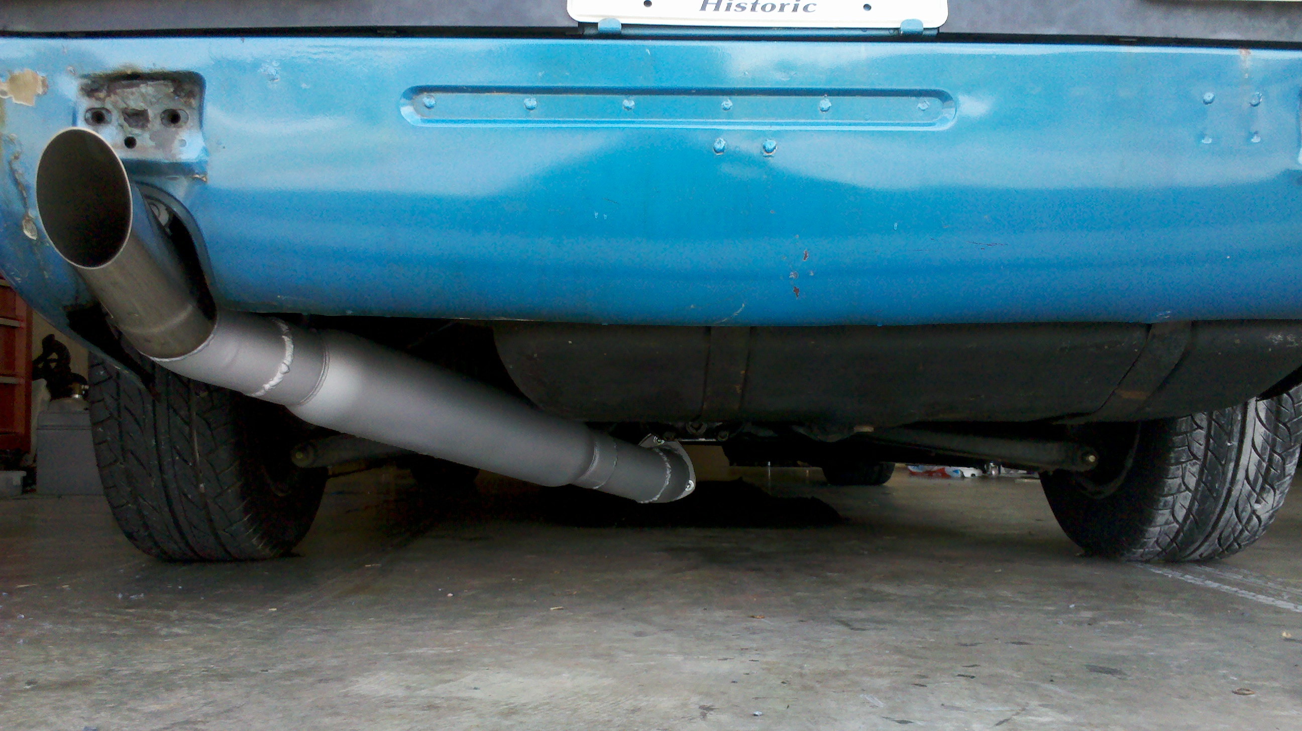
Here are a couple pics of it with the screamer pipe attached. It gets REALLY loud under boost lol. I sprayed it with some DEI high-temp paint, it has since flaked off of the pipe that the wastegate mounts to, but has held up everywhere else on the exhaust system.
-
3" Downpipe, 38MM Divorced Port Wastegate
Cannonball89 replied to Cannonball89's topic in Turbo / Supercharger
I'm not sure what you mean by "angled the wastegate pipe/mount outward". Got any pictures? -
3" Downpipe, 38MM Divorced Port Wastegate
Cannonball89 replied to Cannonball89's topic in Turbo / Supercharger
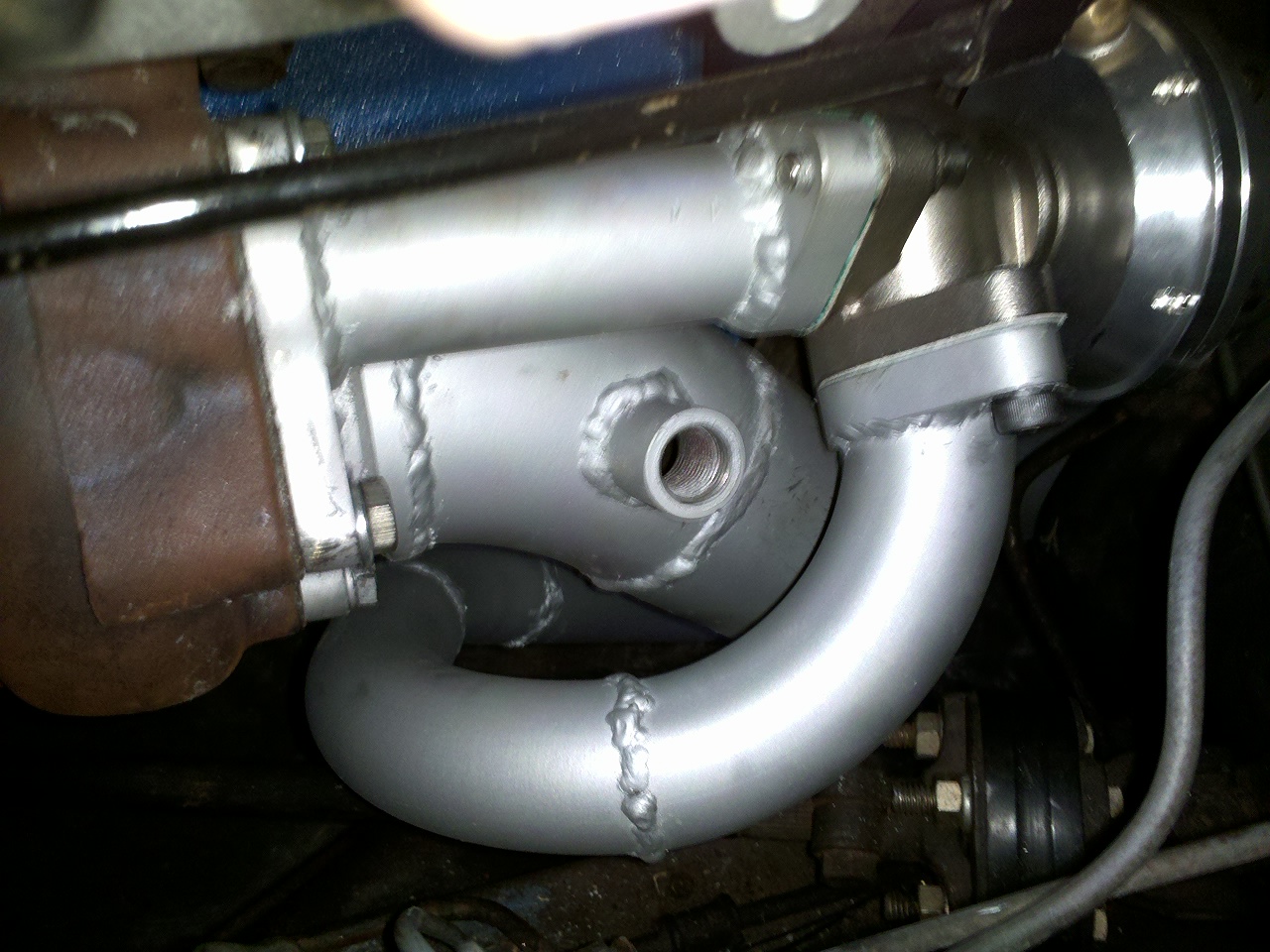
It has been performing pretty well. I have a spring rated at 0.7BAR which is roughly 10PSI. The boost seems to hold pretty steady at aroun 12PSI. So it could just be that the spring is really a 12PSI spring. I don't notice the boost creeping up like I've seen some people's cars, where it will stay at 10PSI then climb rapidly to around 20PSI. I plan on porting the wastegate hole on the turbine housing the next time it is off the car and it should be even better. And yea my welding isn't perfect, I should take some lessons or something. -
Dyno Results and High RPM Voltage Drop Problem
Cannonball89 replied to Cannonball89's topic in MegaSquirt
Well this thread blew up unexpectedly... Question 1: Alternator belt is as tight as I can get it (at the end of the adjustment range on the top bracket and less than 0.5" deflection on the belt at it's longest stretch). Question 2: 80 amp fuse is installed because as you figured out, I don't need all 105 amps, any more draw than 80 amps that would be indicative of a problem and I would like a fuse to blow well before anything melts. Question 3: No I have the mechanical fan still, and have managed to fit intercooler piping behind it (yes it is possible!) Question 4: I have no idea why the vacuum drops low as you floor the throttle, it is something that has shown up in all of my datalogs but has had no effect on driveability or performance to my knowledge so I am not worried at all about it. Yes, I have done the math and I realized that. My spark duration settings were too high and that was the problem. My Spark Duration settings were at 3.5ms and my dwell time at 3.0ms, so basically it was reducing dwell time WAYYYYYYYY too much. The solution to the spark blowout problem was to reduce Spark Duration settings to 1.5ms and my dwell time was raised to 3.5ms. It now seems to pull hard without spark blowout all the way to 6500RPM which is where the spark cut rev limiter is set. As far as MSD, I have always tried to shy away from there boxes simply because my Dad has been through two MSD boxes in less than 10,000 miles on his mustang, and if you look at NASCAR racecars, you will see that they have two MSD boxes mounted on the dash that they can swtitch between, because it is the most likely component to fail on the entire car. Enough said. Yes, The much more detailed solution to all of my current problems can be found in that thread. The dramatic voltage increase at every point in the car is documented in post 14, and the solution to the spark blowout problem is VERY well documented on page 2 of that thread, discussing how Max Coil Dwell and Max Spark Duration settings affect the coil at high RPM. I would recommend you all read that thread for the detailed discussion between me and Tony D rather than make me retype all of that info. I am using the + terminal stud of the starter motor as my main power point. Four wires intersect at the starter motor + terminal stud: The Battery +, Stock alternator + wire (which now only provides juice to the headlights, accesories, and coil), My new heavy gauge jumper wire form the alternator +, and I have a 10 gauge wire that give juice to all of the EFI components besides the coil (2 fuel pumps, 6 injectors, Megasquirt, Wideband 02, Crank angle sensor) So basically the problem has been solved. That is the synopsis. Read my zcar.com thread for the detailed discussion. -
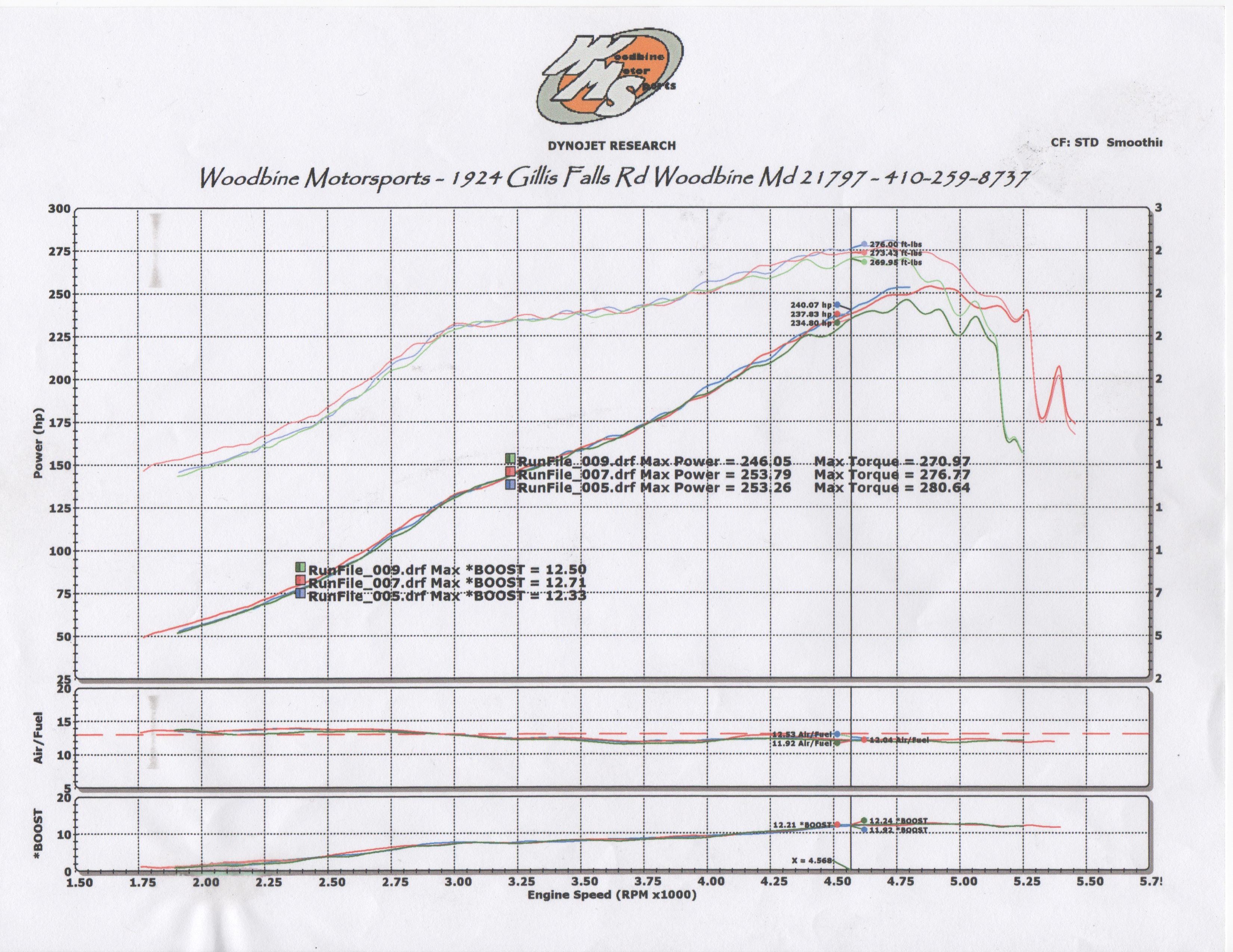
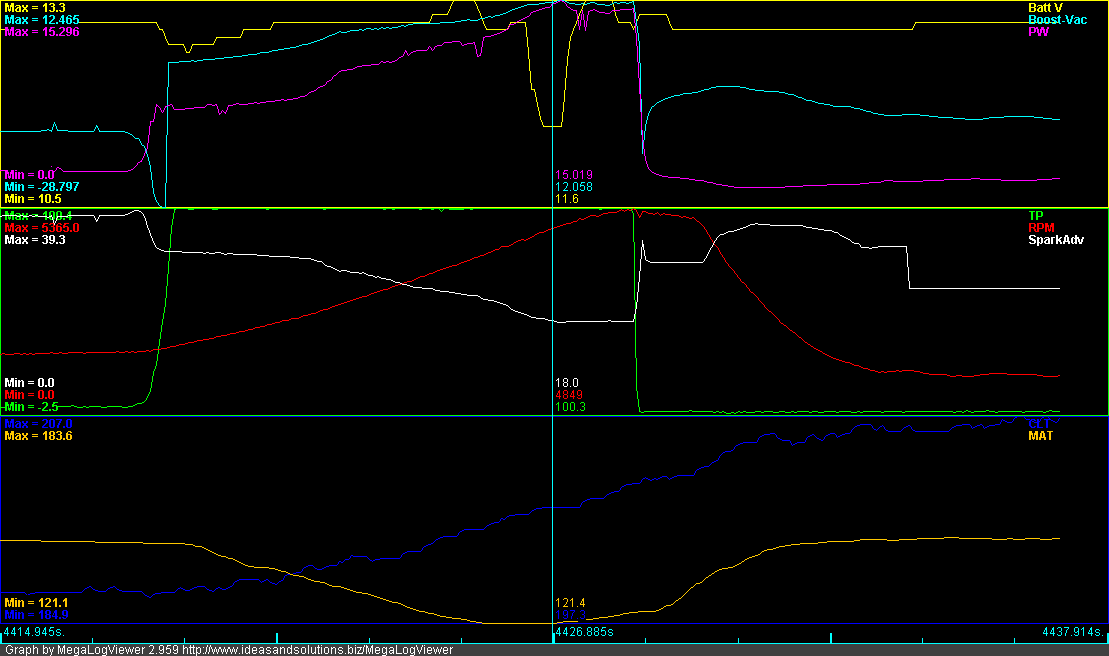
The Dyno session went pretty good. I got my VE table set for WOT. I learned a lot and the car made more power than I expected, but it also revealed a problem. Here is the chart: AS you can see It made 253 HP and 280 lb ft of torque. But you can also see that it really dropped off around 5000 RPM. At first we thought it was detonation, so I backed the timing off from 21 degrees under boost to 18 degrees to see what would happen. It did the same thing. The AFR's were solid even when it started missing and dropping out so we checked the plug gaps, they were nice and tight. So we were scratching our heads for a few minutes and we decided to check the datalog to see what the battery voltage was like. I believe that is the problem. You can see that right about where the power drops off on the Dyno, the Battery voltage is dropping off to 11.6 volts. We believe this is causing the coil to not make a powerful enough spark and basically the boost was blowing out the spark. It also may have interfered with the injectors slightly by looking at how the Pulsewidth becomes unstable as the voltage drops. Here are a few snapshots of the datalogs of my pulls. The yellow line is the Battery voltage. I have the 105 amp alternator upgrade purchased from the Z man of Washington, and it is less than a year old, so we don't think that the alternator is causing the problem. We believe that the stock white/white with red wire is not up to the task of keeping the battery charged when both of my fuel pumps are at full song and the injectors are at a high duty cycle and the coil is firing rapidly. So what I'm going to do run an 8 or 6 gauge wire from the alternator + directly to the battery + with an 80 amp inline fuse and also change the wire feeding power to my megasquirt power blocks from 10 gauge to 8 gauge, and see if this solves the problem. I think I will also install a relay for the coil + side so that the coil can draw power directly from the battery instead of through the stock ignition switch.
-
I wonder if the lon-linear small pulse width feature on MS3 could help your idling problem.
-
I have mine idling smoothly at around 14.5:1 right now, maybe try changing your idle timing settings? If I set my idle VE to make it idle at 12.5:1 it smells worse than it did when carburated. I have also found that leaner than 15:1 at cruise makes it feel jerky and hesitant, but at idle you seem to be dumping a lot of fuel into it. As far as that lean hiccup at very small throttle inputs, I had the same problem, I realized that my 240sx TPS wasn't reading any input until it saw about 8% throttle, it would stay at 0% until it got to where it hit 8% then jump to that. So if your ACCEL enrichment settings are primarily TPS based that could be a problem. I have my enrichments set at 25% TPS based and 75% MAP based, it seems much smoother at tip in that way.
-
I've been driving my recently turbocharged and megasquirted 240z around on the street for a few weeks now. It has been running great and feels really strong under boost, but I now have a Dyno session scheduled for Wednesday (June 22nd) at 10am. The owner of the shop with the Dyno is a very good tuner, he has done a lot of work on my Dad's mustang and some of my freind's Mustangs, but he is unfamiliar with Megasquirt or Nissan L engines. So he is going to be using his tuning expertise to basically help me tune it using my laptop. I have never been on a Dyno before, and at $135 per hour, I want to make sure I make the most of my time. So do you have any advice like what all should I bring with me besides my laptop? Any advice on basically where to start? I'm sure the shop owner will be very helpful but I just want some advice from some people who have had Dyno sessions before to kind of help me know what to expect and how to prepare. The shop is Woodbine Motorsports, they are a pretty big name among the Ford crowd. http://www.woodbinemotorsports.com/
-
The VE analyze is different from the EGO controller, and they will have their own separate control parameters that you will set. The EGO controller will be active all the time that it is within it's control parameters and will basically scale the PW equation by a certain percentage to try to get as close to the target AFR for that given engine speed/load point. The VE analyze will actually alter your VE tables to get as close to the targer AFR as possible. That is the difference, EGO control doesn't alter your VE table, VE analyze will. I recommend saving your tune under a new file name everytime before using VE analyze. My LC-1 is very finicky and I'm afraid it might really screw things up for me if I don't save my tune before using VE analyze.
-
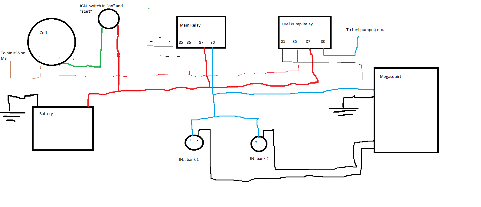
One thing I learned the hard way after having wired everything up is that the CAS needs to receive power from the main relay, not the fuel pump relay as it is shown in my diagrams, so to anyone who wants to use my diagrams as a guide, please change that. Also the second diagram I posted has the main relay and fuel pump relays mislabeled, the main relay needs to have pin 86 grounded and the fuel pump relay needs to have pin 86 going to the the megasquirt.
-
Is this the kind of muffler arrangement you are looking for?
-
Look at this thread: http://forums.hybridz.org/index.php/topic/98694-glove-box-mounting-of-ms-and-fuse-box/ , That is how I wired my MS without the relay board. It takes more time and thought than going the relay board route but it makes things more "modular" in that you can add fused circuits or relays as you please where as the relay board is somewhat limiting in that regard. I liked the idea of hiding it all in the glovebox, and it has been working out great for me so far. A little off topic, but I would love to someday find a PCB company to make me a custom circuit board of my own design to replace the rather large power distribution blocks I am using.
-
I've primed it with my mouth, take the feed line off the pump and suck till you taste fuel, then reattach quickly. Its not the healthiest way but it works. You could probably do it with one of those brake bleeding vacuum pumps too.
-
Does MSII have "Idle VE" as an option for idle control? On my MS III there is an option for "idle VE" where it has a different table set for idle, similar to idle advance, where if TPS is under X% and MAP is between values X and Y after a delay of Z seconds then it references the "idle VE" settings rather than your regular VE table. Having this feature turned on when it is not set properly can make you think that MS is not responding when in fact it is, but it is using your "idle VE" settings rather than your normal "VE" settings in it's injector pulswidth equation. My recomendation would be to search your menu in tunerstudio/megatune and see if you have an "idle VE" setting and turn it off for now, then experiment with it after you have the motor running smoothly on the standard VE table.
-
I mispoke about cranking RPM. What I should have said is that if the cranking RPM is set too low in Tunerstudio/Megatune, then MS won't fire the injectors at the cranking pulsewidth. IF your cranking RPM is 135 RPM, then your cranking RPM setting should be at least @ 200 RPM. Anything above what your cranking RPM setting is at will fire the injectors at whatever pulsewidth it derives from your table settings. Lets say your cranking RPM is set at 100 RPM... then at 135 RPM it will be trying to derive a pulsewidth from your table settings, which probably only go down to ~500RPM or so, so basically MS might calculate a 0ms Pulsewidth. See below for an explanation of the +12V to the injectors. I see the diagram you are using, it looks good... The thing is that in an S30 you have to wire the relays such as that they are active with the ignition switch at both the "on" and "start" positions. Basically you need to have pin 30 or 87 coming from a constant 12V source and the other going to the load (in this case the injectors), then either pin 85 or 86 hooked up to ground and the other hooked up to a switched 12V source. The only good switched 12V source I could find on my 240z was from the coil + side, this is hot at both the key "on" and "start". Almost every other circuit on a 240z is either constant 12V or is 12V when the ignition switch is at "acc" or "on" and are open circuits when the key is on "start" To clarify I made a quick diagram showing my relay wiring. I would also recommend testing your wiring by disconnecting the "S" terminal form the starter and then checking to see if you have +12V at the injectors with the key on both "on" and "start" Sorry for the childish looking diagram but microsoft paint is about the only way I have to make wiring diagrams
-
What is your cranking RPM? If that is set too high it might cause that. Also what is your cranking pulsewidth? If its at 0 then that could be your problem. Another thought, where is the +12V to the injectors coming from? If it is coming from any circuit on the accesory relay it will have no power during cranking. Good luck, hope you figure it out.
-
What are the specs on the resistor you installed inline on the o2 input to the megasquirt? I don't know if it would make any difference but I will try that.
-
I am really starting to hate my Wideband, an Innovate LC-1. It will work sometimes, then for no reason whatsoever, it will not produce an output to my Megasquirt. I have done the heater calibration and the open air calibration several times, and it seems to work right after I do that. Then If I turn the car off and turn it back on again, no output to MS. What I see when turning the key on is that it will register 7:1 AFR (which = 0V) when warming up the sensor, then after sensor warm up is complete it will go to 22:1 AFR (which = 5V). Now sometimes once the engine is running it will show the actual AFR, then other times it will stay at 22:1 and its like it doesn't know the engine is running. It is so random and frustrating. I want to start tuning my car but there is no way I can trust this LC-1 to give me reliable readings when it only seems to work intermittently. And I really don't want to use the VE analyze/autotune feature with it because it is hard to say what it might do to my VE table if it goes to a steady 5V output and MS thinks the AFR is 22:1!. I have checked my wiring numerous times, the grounds are good, grounded to the same point on the engine block that the rest of my MS components are grounded to. I have made sure that I have MS hooked up to the 0V-5V output wire and not the narrowband simulation wire. I have also hooked up the LED to see if there are any trouble codes, and the LED indicates that there are no problems whatsoever, even when it is sending a steady 5V output! Basically I am about ready to through this thing out and buy an AEM or Greddy or something like that. I have been reading on other forums about Innovate LC-1's and the general consensus is that they are garbage, and AEM makes a much better product. What are you guys using? Any advice or recommendations?
-
Not trying to ruffle any feathers guys, sorry about that. I think golllum laid out all of the advantages and disadvantages, it just seems to me that when designing a compact motorcycle enigne, I would have used a more modern engine as the template, but that's just my opinion. Sorry.
-
Can someone tell me why a pushrod valve engine is still in production today? I've been wondering for years...
-
On my N/A L24, the headers seemed to hurt performance at low RPM, but did help the top end a little. The thing I loved most about the headers was how awesome it sounded with my twice pipe exhaust. On a turbo motor, I figure that the sound will never be the same as an N/A with headers just because of the muffling effect of the turbo, so the only advantage I could see for a turbo street car making 250-400HP would be the look of a bundle of snakes going to the turbo, but on our L-series motors you can hardly see the turbo with the intake being over it, let alone the manifold going to it, so I don't see any justifiable reason for a turbo header on a car making moderate power, like Tony said. If our L-series engines had the intake and exhaust on separate sides of the engine like modern engines, then I might consider spending money for a turbo header for the look of it and the possible slight performance gain (because street cars will naturally be shown at car shows, I don't really consider it "rice", more like "showing off") I'll just be happy to be driving my car again, I'm so close to getting my car driveable again, just keep hitting minor roadblocks like my LC-1 crapping out making it impossible to tune...
-
If you use an LC-1 wideband O2 sensor then it has an output to the ECU and an output to the gauge coming off of the module, so now splitting of wires is needed. For sensors it is pretty simple to recalibrate MS for the stock sensors, and the ohm values are documented on this site. It also isn't hard to fit the GM sensors that MS is allready calibrated to onto the engine, just a matter of tapping the manifold and/or thermostat housing for NPT threads. Personally I decided to use the stock cylinder head temperature sensor for my coolant temp sensor, just because I cracked my thermostat housing trying to tap it for NPT threads. For the IAT sensor you probably have to use an aftermarket sensor because I think the stock one is built into the AFM, which you won't be using. I have mine in the #4 intake runner because my intake manifold allready had a large threaded hole there that I think the stock recirculation valve threaded into. But a lot of people put a bung on their intercooler piping. Don't worry about finding the stock harness, you won't be using any of it hardly. DIY sells the DB37 connector that has all of the sensor wires allready connected to it, and it does make the installation simpler. You will still have a lot of custom wiring to do but it's not that bad. You can also either opt to get the relay board or do something custom like I did, here is a link to the thread for my custom relay board, just to give you an idea: http://forums.hybridz.org/index.php/topic/98694-glove-box-mounting-of-ms-and-fuse-box/ Sheilded wire is used to prevent "noise" from interfering with the MS. basically your TACH signal is a very low power signal, and things like fuel pumps, injectors, and coil are very high power. These high current wires can transmit EMI to your TACH signal (or any other sensor for that matter) and make the ECU get a false reading which will cause it to lose sync. The shielded wire helps to prevent this. There are many other steps necsessary to prevent noisy signals though, a quick search will reveal many threads dealing with that matter.
-
Discussion About Pressure Being Resistance to Flow.
Cannonball89 replied to jc052685's topic in Turbo / Supercharger
I never could understand how Porsche was able to turbocharge air cooled motors for so many years and still make them reliable and not overheat until I understood what Cygnus is talking about. Large turbos that provides little restriction to the exhaust flow and free flowing heads and intake were the only way that they could accomplish that feat. -
Congratulations on getting your engine running on MS! Although it is something that many of us have done it is still an accomplishment to be proud of. Now after figuring out all of the technical details of Megasquirt, I find it hard to believe that you can't figure this one out. Really, if you don't have an idle valve or anything then it has to be something external to MS. Likely a huge vacuum leak or your throttle stop isn't adjusted properly on your throttle body. The only way MS could change your idle speed is by changing the mixture but that would only slightly alter it, if your idling at 3500 RPM the you have something external to MS wrong. Toolshed?
-
I have my tach input running on the VR circuit with the potentiometers set with R52 all the way counter-clockwise and R56 two turns clockwise from fully counterclockwise. I also have added a 1K resistor to the pads marked R57 on my V3.57 board. I don't fully understand the theory behind the potentiometers, this page will describe it much better than I can: http://www.megamanual.com/ms2/vradjust.htm Just keep in mind that I have a different board and also a different firmware than you, so the way mine is configured may not be what you need. Do you have a stim? I really don't know what else you should try other than seeing if you get a TACH signal on the stim.