

toolman
-
Posts
616 -
Joined
-
Last visited
-
Days Won
25
Content Type
Profiles
Forums
Blogs
Events
Gallery
Downloads
Store
Posts posted by toolman
-
-
PART 18- GULL WINGS DOORS RUNS INTO A PROBLEM
The Gull Wing Doors run into a problem with the Roof Shape turn into the Vertical Window Shape. That Tight Shape creates additional fabrication work.
Another problem coming up will be how to seal the Gull Wing Doors with weatherstripping and create enough gapping around the Wing Doors.
-
Converting the 240Z Passenger Seat in a Reclining Seat
I found a need to convert my Passenger Seat into a Reclining Seat to gain additional Space. I know later models of
Z cars 2 PLus 2 need to have Folding Seats to allow additional passengers into the Rear Passenger Compartment.
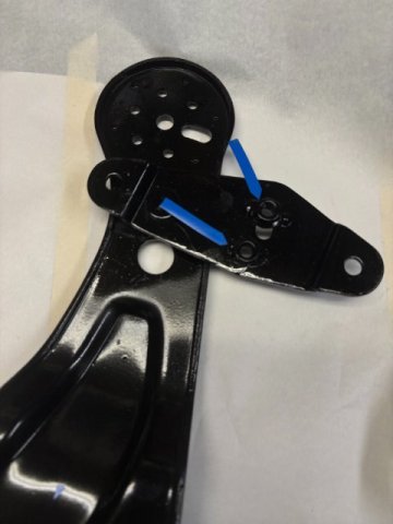
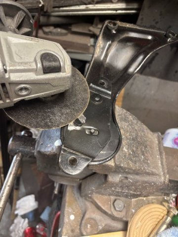
So i removed the Factory Seat Tilting Mechanism and examined carefully. The mechanism consists of a Tilting Cam that
limited the Seat Tilt to 15 degrees. A Steel Center Pin, in this case, operated as a Pivot Pin. So, removing the Cam and
removing the Two Steel Pins should allow the Full Tilting of the Seat Back. First, Both Steel Rivit Pins had to be removed.
A 4 1/2" Rear Angle Grinder with a Gringing Wheel was utilized to remove the pins from both brackets.

Grinding the Rivet Heads off with Grinder
Removing the Two Steel Pins-see Blue Arrows
Internal Parts of the Seat Brackets
Two Removed Rivets, Limiting Cam, and Outside Plastic Knob
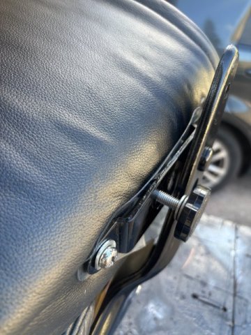
Weld two 12mmx 1.25 nuts to the Bracket Arms
Amazon sells the new Plastic Knobs with 8mm x 1.25 x 30mm for $15.
They come in a pack of Four Knobs but you only need Two per Side unless you convert the Drivers Seat too.
Insert One Knob in the Center threaded hole to Lock the Seat in Upright Position.
And Another Knob inserted in Center Hole for other side.
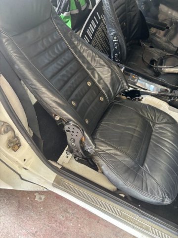
Seat Folded Flat with both Knobs Removed-Maximum Space Available.
With Both Knobs Inserted , Seat in Normal Position
With Both Knobs Removed- Laying Back -Sleeping Position is possible.
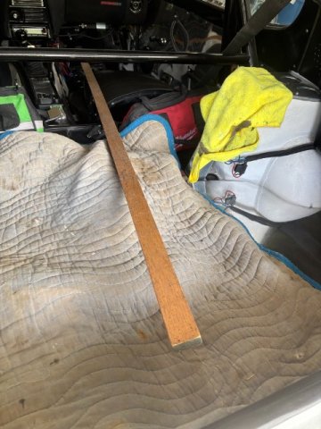
With Seat in Folded Position- There enough Space to Several 8 Foot Pieces of Lumber in your Z now.
i hope this project will make your Z more useful and comfortable.

-
 1
1
-
-
PART 17- Fabrication work on the Gull Wing Doors is going at FULL BLAST!!!
Detailed fabrication work on the Gull Wing Doors is very impressive. Actually, some of the work to correct "mistakes" are truly expert workmanship in action.
Years of experience demonstrated how to solve problems.
-
PART 16-Work on the Gull Wing Doors finally begin!!
After all the reinforcement of the 260 body structure with a huge roll bar cage, the work on the Gull Wing Doors begin. Some people did realize that
the Gull Wing Doors required such major structure modifcations. You are practically cuttting the vehicle in Half then installing a full function Gull Wing Door section.
But the Time is still ticking away--only a little more than 4 Months away from SEMA SHOW in November. Also, Shipping Time would be about a m
might have to Air Freight the 240Z to Las Vegas. As most Sema Show cars, it will a "Wild Race to Finish the Car" with "All Hands on the Deck"!!!
-
Part 15- The Rear Suspension is finally attached to the Middle Body Section-
The Video deals with attaching the Rear Suspension to the Middle Body Section. The Gull wing doors require additional reinforcement to the Middle Section of the
260Z. This is similar reinforcement when installing a Convertible Top on any production vehicle. With only a small center section of the roof that must support the weight
of Two Doors and provide structural support for the Roof Area that will cut be out will be a
nightmare.
-
Part 14-Finishing the Rear Suspension
Finally finishing the Rear Suspnsion and getting ready to put the 260Z on the ground.
-
PAFT 13-INSTALLLATION OF AIR BAGS TO THE REAR SUSPENSION
A CUSTOM AIR BAG SYSTEM was added to complete the Rear Suspension. The Bag Mounts were fabricated to mate with the Rear Frame rails.
-
Part 12- The Rear Suspension is being finished, The Rear Major Structure was fabricated and tied into the existing frame and roll cage. The installation of the Rear
Air Bag Suspension will complete this effort. This project still has to fit the Mercedes Engie and Transmission into the car, do the electrical wiring, install fuel tank,
complete front steering and suspension and do the bodywork and paint. All these things done in less than 4 months to make the Sema Show.
-
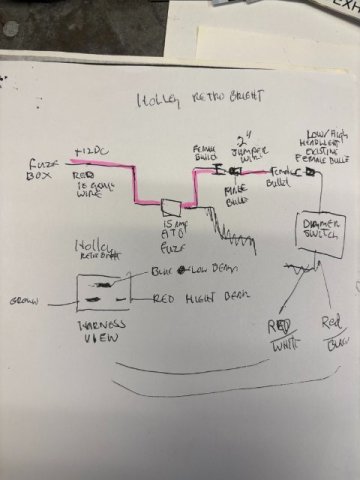
Holley Retro Bright LED Headlights Installation-
I decided to improve my Night Driving by installed Holley Retro Bright LED 7" Round Headlights. Although
they are expensive at about $500 for a Pair. Safety is very important and driving at night needs good lighting.
These Holley LED light were tested todraw only 6 amps on High and only 4 amps on Low. Power consumption
was only 25 watts. Just imagine if your alternator failed only producing low voltage while you were driving in some remote road, your headlights would still perform while regular headlights may not provide any light.
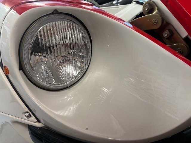
The Retro Bright 7" Round Headlights match the Original Look which seals the Deal. Actual Driving at
night really shows the difference -Its Wide and Band of Bright Light makes Night Driving much better.
I found this posting on HybridZ-that gave detailed info on installation of Hlley Lights and used it.
-
Part 11- trial Fit of the 370 Rear Drive Sewction into the 260Z.
In this episode, the Car is finally on the ground for Rear Suspension construction. Since they are using a Fiberglass
Hatch Delete section, there will be very little space for anything else but a Fuel Tank Cell. the major problem is time
to finish the car as they are not even at the half way point of the build. The craftmanship truly amazing as they solve problems with building a one of kind vehicle.
.
-
1
-
-
Part 10-Middle Connection Frame Rails are fabricated and installed.
In this this video, the Frame Rails connecting the Front and Rear Frame is being constructed and installed. It is pretty heave duty but besides acting as a
regular Body Frame, it must also support those Gull Wing Doors. As the Roof will have be cut out for the doors too, extra support must be provided for door operation
and replace the roof structure. I imagine the roll cage have a strong Center Roll Bar Section to accomplish this task. The Doors will be a major problem with sealing and allowing adjustment of the Gull Wing Doors;
-
PART 9- ROLL BAR WELDED IN AND FABRICATING SQUARE TUBING INTERMEDIATE FRAME
Thing are really moving along now. The Roll BAR is welded in and a frame connecting the existing front and rear frame rails is being fabricated.
Excellent metal fabrication is demonstrated. i can for see that the original Transmission Tunnel will have to be removed to provide clearance for the Mercedes transmission. e Firewall probably have to be widen also.
-
EXHAUST SYSTEM REPAIRS-
My 240Z Exhaust Pipes were damaged from scrapping them on Speed Bumps. I found a cracked at one
welded joint and a few exhaust leaks. Since repair required their removal, I decided to raise the pipes higher as the
same time. I designed this exhaust system so that whole system consists of three major sections. First -Front Section
goes from Hooker Exhaust Manifold to the X-Crossover pipe. Second Section runs from X-Pipe to the Rear Right Angle
Exhaust Pipes. The Last Section finishes at the Two Turbo Mufflers. So this repair and raising the pipes only required
the Intermediate Pipe. Also, since I used Evil Energy V-Band Clamps to connect the pipes, it was a simple job.
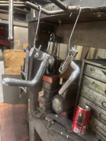
The Intermediate Pipe Mount consist of 1/2" Steel Rods bent at 90 degrees and bolted to the Differential Housing.
To Raise the exhaust pipes, only the Mating 1/2" Mounting 90 degree Rods had to be shorten.
Pic of Mounting Rods cut off and rewelded
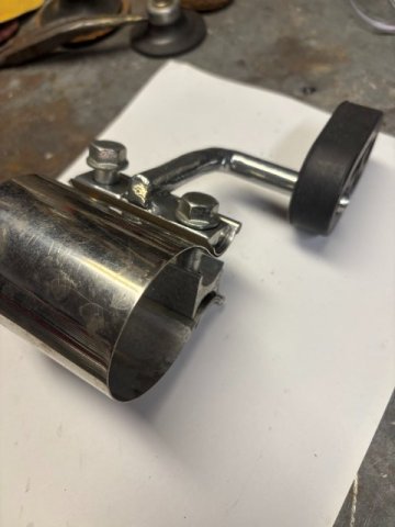
Pic of Mounts Powder Coated and out of Oven
Pic of Fully Assembled Exhaust Mount
Evil Energy 2 1/4" Lap Joint Clamps( Amazon $20 a pair)
Rubber Exhaust Pipe Hangers(Amazon-$6 a pair) and 1/2" Steel Rod-Bent to (90 Degrees-Home Depot)
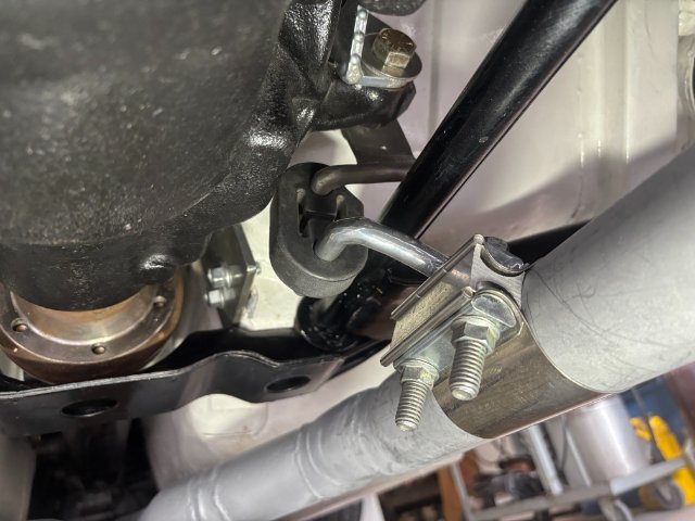
Right Side Pipe Mount
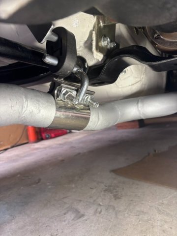
Left Side Pipe Mount
The Exhaust Pipes were raised about 1 1/2". The job can be accomplished in one days if materials were at hand.
-
Part 8-The Roll Cage is now installed so the Roof Area is being prepared for the Gull Wing Door Build. A Major Obstacle that I foresee the Transmission Tunnel and Firewall
may have to cut open because of the Huge Mercedes Motor and Transmission. But if they are willing to Eliminating the Tunnel and Widening the Firewall Opening, they should not be a Big Problem.
-
Part 7-More work on the Rear of the Hatch area to install the 370 Rear Suspension Subframe. The Entire Rear Deck and Frame must be removed to make it fit.
The Workmanship is excellent and the Shop High Tech Equipment makes this big job alot easier.
https://www.youtube.com/watch?v-EY6HaMiWFE48&t37s
----
-
Part 6-Major Problem delays SEMA PROJECT
A major problem occurred in using a late model 370z suspension into this SEMA SHOW car. Its wider size and different mounting points created
a major obstacle in this construction, Time is the Real Problem so this build will be exciting to watch.
-
Second Owner of the SEMA SHOW Toyota A86 Body
The First Owner of the SEMA SHOW Chinese Made Copy of the Toyota A86 Body decided to sell the body. The real question is why? The next Owner
bought it with the idea of attempting to assemble the body and create a drivable car. As the body has No VIN Number and No Manufacturer ID Number, they
knew that car registration in most states would not be possible. They intended to use this body as a Race Car as no registration would be necessary.
As the video demonstrate that most mounting holes that not align with OEM parts. Also, they discovered a lack of sufficient welds on the body panels.
Mounting brackets were missing or mislocated. So even if it was going to used as a Race Car, major welding and reinforcement of the vehicle would be necessary.
So far, there has no one that I know who purchased a 240Z body from this same manufacturer. So far, we could not get a firsr hand through inspection of the Zbody
and find if that body is manufactured better or not.
-
 1
1
-
-
10 hours ago, toolman said:
Part 5-Major Problems in the build -time may run out before the car is finished.
https://www.youtube.com/watch?v=DcXWWiwmGSI
-
Part 4-Fixing the Gull Wing Doors and create special Interior design work
Finding a mistake costs a lot of correction time but when you doing a one of a kind project that is to be expected.
Go to---https://www.youtube.com/watch?v=itN99F8VKbQ
-
Part-3 The Whole Plan is explained in this Video,
Liberty Walk Body Kit and other exterior modifications are exposed. But Time is the greatest enemy as the Sema Show is now less than a year away.
go to ======https://www.youtube.com/watch?v=Merq9wrCZns
-
PART 2- Working on Gull Wing Doors
Demonstrating the process of converting old door shell into the Gull Wing Door. Fabricating new door frame from scratch is something to be hold.
The craftsmanship is excellent. Their equipment is First Class and expensive. Most body shops don"t have access to scuh expensive equipment
but work can duplicate by regular metal working tools but taking more labor and time.
Go to https://www.youtube.com/watch?v=LGEWDhsnRoE for video
-
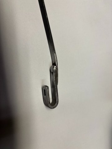
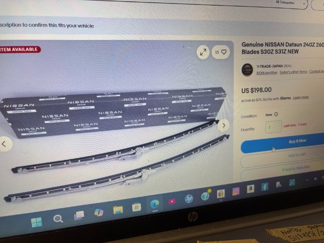
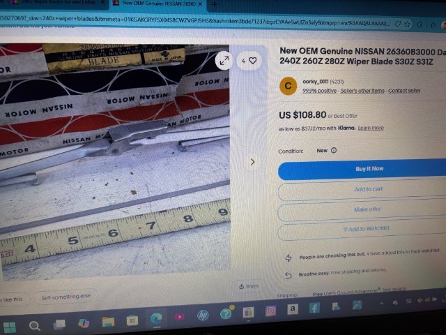
240Z Wiper Blades Problem
The problem with the 240Z Wiper Blades is their availability. As these cars go older, their parts tend to
almost impossible to find. When found, they cost about $200 on Ebay. Those Universal Wiper Blades use
a Plastic Universal Adaptor. However, these Adaptors don not hold the Wiper Blades to the OEM Wiper Blade
Arms. Mine came off during a rain storm several times. The last time It scratched my windshield glass but
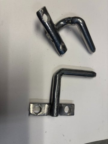
fortunately it was polished off. So I decided to see if I could create a better design. Most Late model cars
use a "J HOOK" design Wiper Arm. So I went to the Junk Yard and got two arms. As I was a regular customer,
the owner said "just take them, I got hundreds of them". After carefully measure the distance between the Wiper
Nut and the End of the Wiper Blade Tip. I just cut the donor arm about 3" off. The Univerisal Wiper Blade was installed
on the J Hook. Then, slide the J Hook piece on the OEM wiper arm until the measurement was acheived. A Visegrip
Plier was used to hold the two pieces together. These two pieces were tackwelded together. The newly form
wiper arm was installed and tested thru its full arc. When that was achieved, I fully welded the two overlapped pieces together.
A Simple Fix for the Wiper Problem. Very Low Cost and ended up with a Wiper Blade that will always be Available.
Those those of you who want the original Blade-just keep the OEM one in a safe place and make one for every day use.
Unless you can afford $100 when your blade wears out.
-
This video is the Second Video concerning the Toyota A86 reproduced assembled body. They have several individuals that discuss the quality, licensing, and infor
about this car body.
In my opinion, the more detailed pics of the alignment and welds show that this body was not assemblied properly. If even used for the street, the body would require closing the panel gaps and alot more proper welding. Unitized bodies require proper panel alignment and sufficient amount of welding to provide a safe cafe.
Please give your comments about this car body. Remember this same company manufactures the 240Z assembled body also.
-
The Video is the most detailed Rebuild of the Power Brake Booster Unit. As the 240Z family goes older, aftermarket rebuild boosters
are getting harder to find. In some cases, they are impossible to find so rebuilding maybe the only solution.


 Pic of Mounting Rods cut off and rewelded
 Evil Energy 2 1/4" Lap Joint Clamps( Amazon $20 a pair)
A 2026 SEMA SHOW 260Z Build all the way from Great Britain
in Body Kits & Paint
Posted
Part 19-More Detailed Work on the Gull Wing Door
More Detailed work continues on the Gull Wing Door- Drain Channels and Gapping the Door in preparation for weather stripping.