

toolman
-
Posts
525 -
Joined
-
Last visited
-
Days Won
9
Content Type
Profiles
Forums
Blogs
Events
Gallery
Downloads
Store
Posts posted by toolman
-
-
Yes, I am trying to keep some things original as possible.
Back to Fuel Pump Modifications:
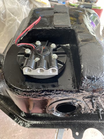
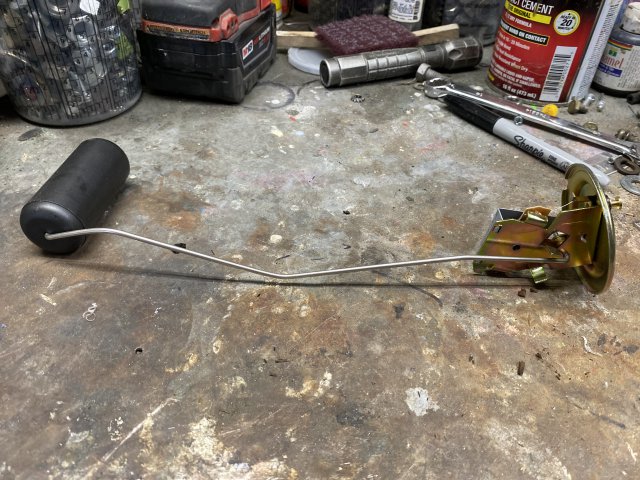
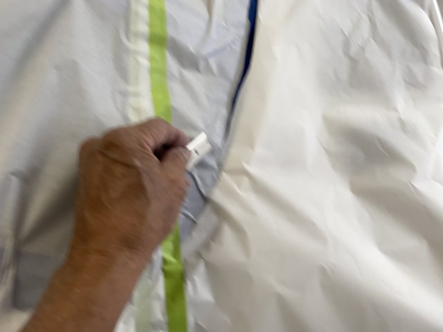
After measure the tank depth and setting the pump length. the pump was installed.

This pump can be rotated any direction that you prefer without drilling new mounting holes.
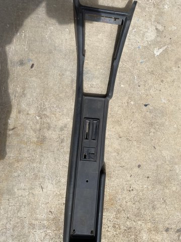
Left to Right- Return Line, Fuel Feed Line and Vent Line.
The pump mounting bolts were torqued to 50 in lbs in a Star Pattern and three increments.
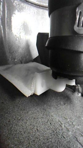
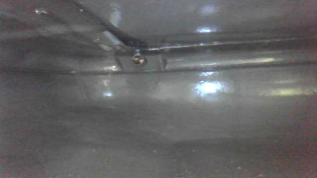
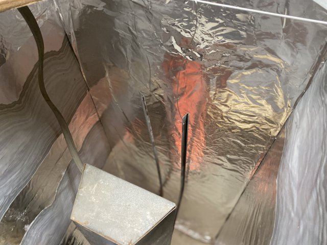
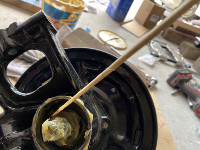
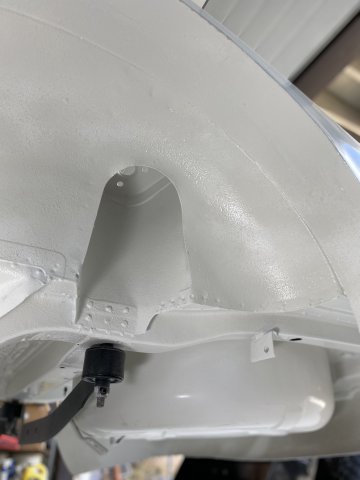
Using the Borescope, you can see the filter on the bottom of the tank inside the surge tank.
View of upper side of Fuel Pump
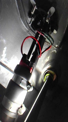
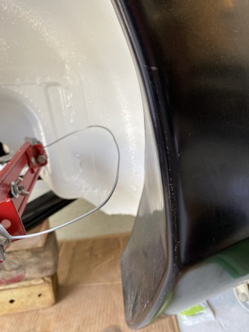
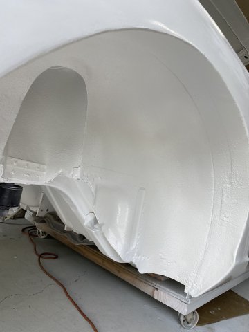
Because of the Fuel Pump location, the new Fuel Sender Unit had to be modified to clear the walls of the Surge Tank.
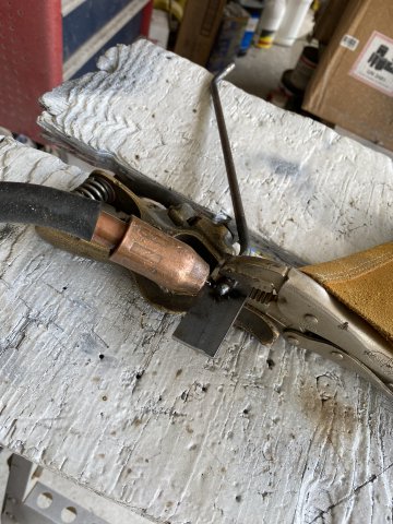
Using a Vise Grip, the Float Arm was bent to clear the Surge Tank Walls. The Float Arm can be adjusted further after putting Fuel in the Tank and comparing Fuel Gauge reading,
A 100 micro Inline Fuel Filter was installed between the Pump and EFI fuel Inlet.
This Filter
This Filter uses a Stainless Mesh Filter so it is reusable.
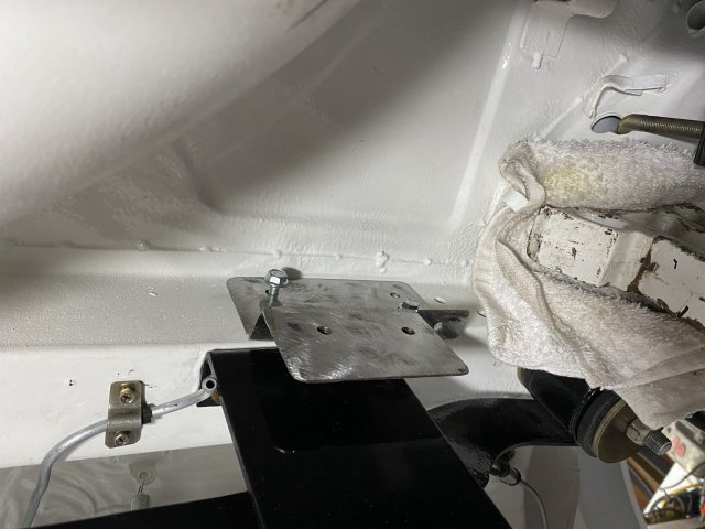
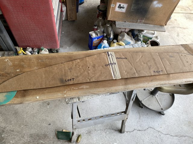
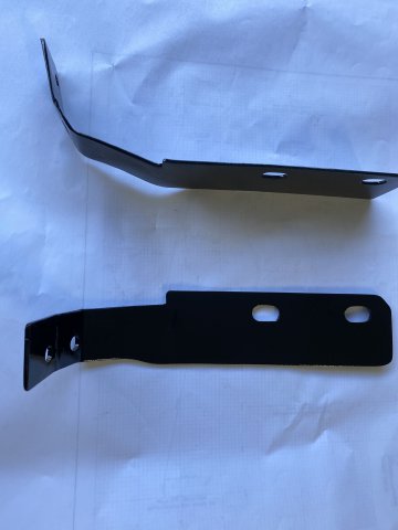
A Two Piece Bracket is constructed to hold the Fuel Filter.
It was made of 1/8" plate Steel.
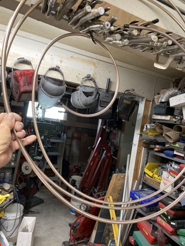
4Life Nickel Copper Fuel Line 3/8" x 25 feet purchased from Amazon. Came by Federal Express in a small 18" x 18" x1" box in
one big coil.
Start by slowly unwinding the coil slowly keeping the roll as straight up and down as
possible. When the roll is about 6 feet high, it is time to go outside. Use you feet to hold the lower part of the roll as you are unwinding and sliding your feet on the line.
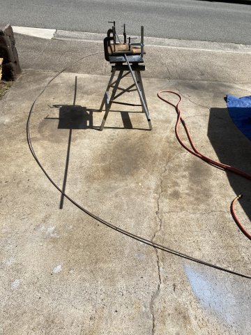
Keep going till the line is relatively straight. Cut the line in half to about 12 1/2 feet long to make it easier to handle. A straight piece of 1/2" electric conduit(about 7-8feet)
was fastened to a portable work bench using two Vise Grips. The conduit should be small as possible for the best result.
Sliding the tubing back and forth rotating the tubing at the same time. Eventually the tubing should come out relatively straight.
Next Step to Make AN Fittings and Braided Steel Hose for the Fuel Lines.
Happy Turkey Day to All!!!
The bracket will be powercoated when completed.
-
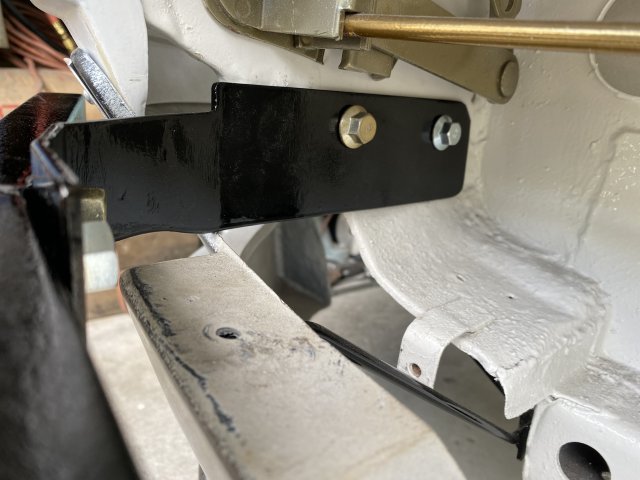
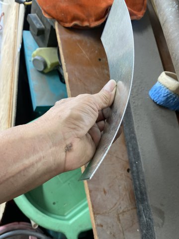
The picture is not that clear. Can you take more at different angles? The center section is cast and can not be welded. The other possible
fix is to braze the lever (stamped steel) to close the gap and file to fit. Filing will take awhile so do not braze more than necessary. This will
work as long as the cast side can take the turning torque.
-
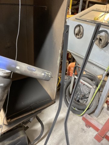
I was fortunate to come across a Great Deal. I sold my "old" sandblast cabinet for $350 then upgraded to Bigger One for only $150 more.
This cabinet is twice as large and has top and side access doors. Plus it also came with a 4 foot high dust vacuum.
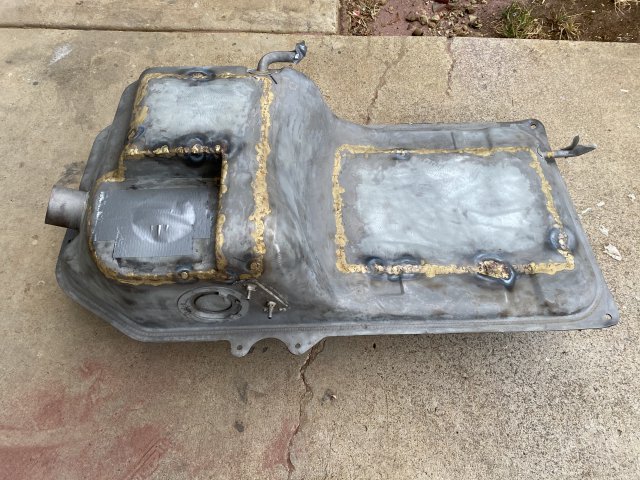
Fuel Tank Modifications:
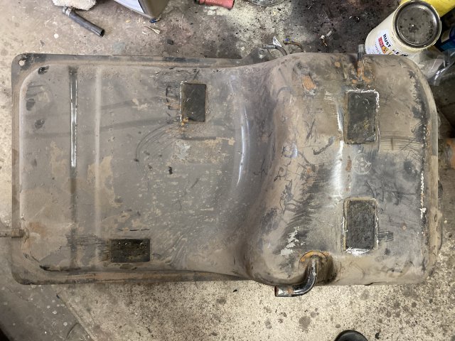
My Fuel Tank was really rusty inside and had a lot of large dents on its bottom.
Note-Remember the Pads positions.
After Blasting, the dents were more visible.
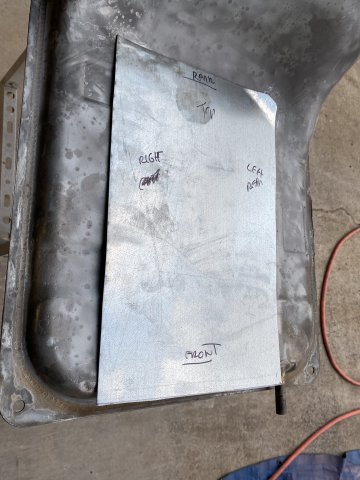
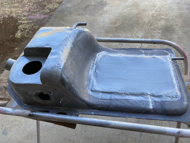
The only way to remove most of the large dents was to cut open the top of the tank and push the dents out. This method would however allow for sand blasting of the inside of the tank.
After cutting the tank, a patch was created to repair this area.
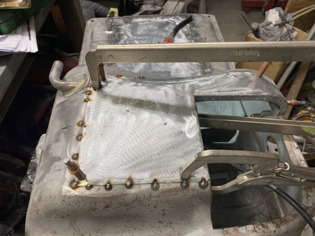
Visegrips and Cleco Pins hold patch.
getting ready to weld
All the mig welds were brazed over to further prevent tank leaks.
after Brazing.
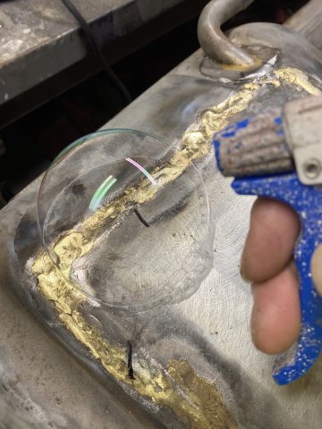
The welds were checked by applying 2 PSI of Air while spraying a Soapy Water.
Leaks are easily found with this method.
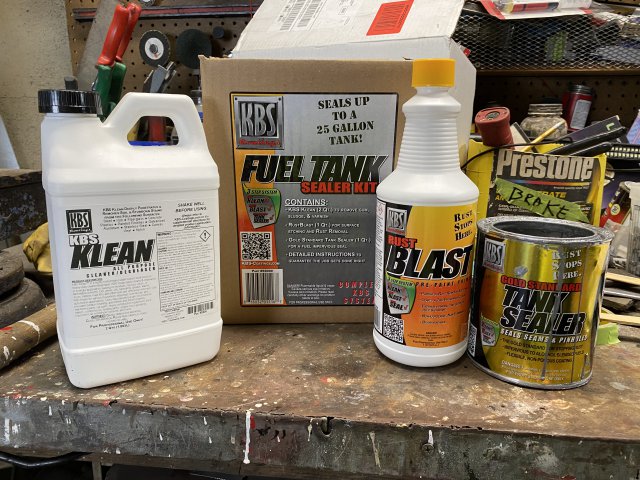
KBS TanK Sealer Kit is an additional step to further prevent tank leakage and provide corrosion protection.' This sealer covers the entire interior of the fuel tank. It is also one of the few tank sealers that is not effected by ethanol fuel.
Cost about $80 from local industrial hardware store.
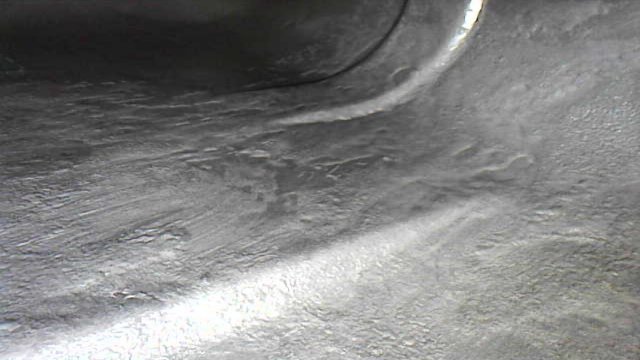
Bottom of tank after KBS Sealer install
Upper side
The KBS Sealer was also applied on the exterior welds for additional sealing.
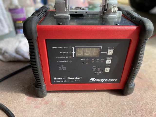
I borrowed a Snap On Tools Smoke Machine. This machine is used to check for leaks in automotive fuel and vapor systems.
All openings first plugged up.
Then, Smoke is pumped in and for any smoke leaking.
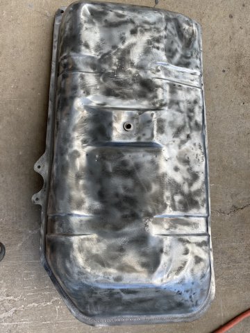
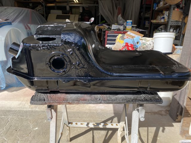
The Fuel Tank passed the Smoke Test so painting the exterior was next.
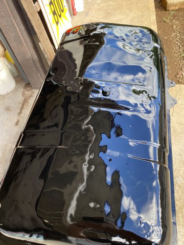
Epoxy Urethane Primer was applied.
Bottom View-after Urethane Black painting.
Side View
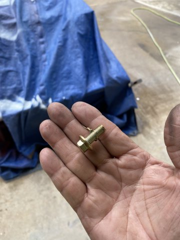
Holley #19-350 EFI Fuel In-Tank Pump( from Amazon $325) was selected for the task.
It is a very compact and well build unit.
Next- Fuel Pump Installation and Fuel Sender Modifications
Happy Halloween!!!!
Got this borescope from Amazon for about $30. It also can take very good pics too.
The Fuel Pump Slump was constructed out of sheet metal and brazed to the tank bottom. Note the maze shape protects pump from excessive fuel movement.
-
Sorry for not posting for awhile, I had some home repairs to do before the end of Summer.
Undercarriage Work:
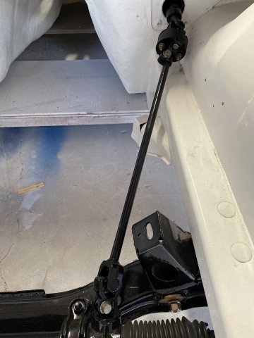
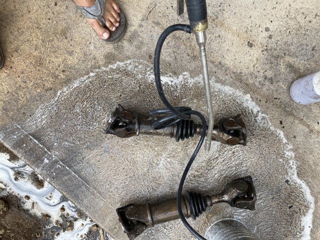
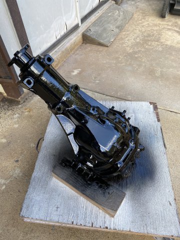
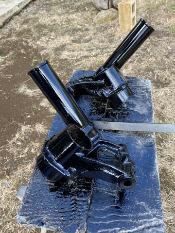
Disassembled and cleaned then lubed and reassembled the steering components.
Disassembly, inspection and relubed
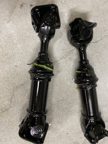
All parts were painted with Black Single Stage Urethane paint
The Gas Pedal Bracket was left as it depending on LS Electronic Pedal Assembly.
Brake, Vent and Fuel Lines
All Lines were wire brushed, primed and paint with Single Stage Silver Paint.
One Part of the Drivetrain Tunnel was the Hand Brake Mechanism which was missing its Dust Cover Rubber Cap. I found a !" chair leg
plastic cap from the local hardware store that fit perfectly to seal the Hand Brake Swivel Ball grease in.
Cap with hole cut on top
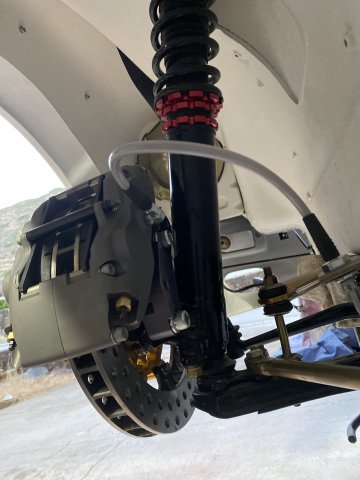
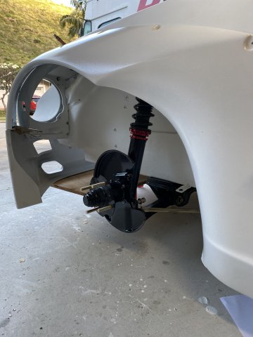
Front Disc Brakes Modifications
My WILWOOD 300mm Rotors and Four Piston Calipers arrived in time for installation.
From Techno Toy for about $1200
comes with braided stainless steel lines.
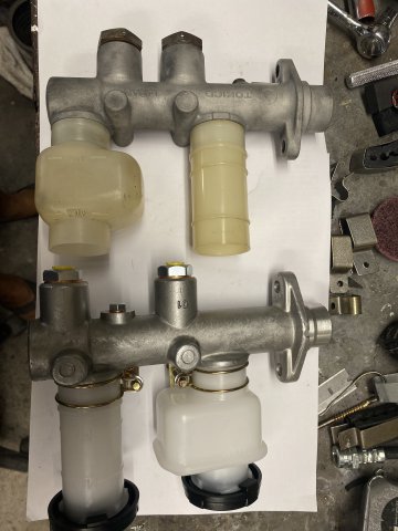
I replaced the Master Cylinder Assembly with another 7/8" one from ZDEPOT. OEM master cylinder assemblies were only available for about $300 as compared to ZDEPOT for $100. But the output brake lines must be bend to fit for ZDEPOT one.
ZDEPOT OEM Master Cylinder
Note- Difference in Outlet Fittings in both assemblies
Also Note-Differences in Reservoir positions
New Brake, Vent and Fuel Clamps were fabricated for the drivetrain tunnel section.
Next thing to work on will be the Fuel Tank modified for In-Tank Electric Fuel Pump.
-
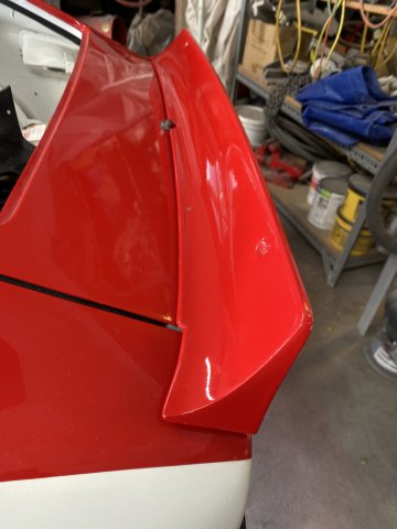
Mounting Rocket Bunny Rear Soiler
The Rocket Bunny Body Kit does not come with any instructions for installation of its components. So the builder has to come up with
his own methods of installation. The rear spoiler is no exception. I decided to mount the spoiler by fabricating Two mount plates that were
installed inside of the spoiler.
Each mount consisted of Two 5mm x .8 x 16mm bolts that were tack welded to
a 1/2" x 3" long 16 gauge sheet metal plate. The mounts were mounted on the both side edges of the hatch. The existing hatch edge was
1/8" thick already and strong enough to hold the spoiler on.
Test fitting the mounts
Create a cardboard template of mount to make sure the mount would fit inside of the spoiler.
I determined that a 1" hole drilled in the bottom of the spoiler would sufficient for installation of the mount and not be "too large".
The bolt holes were also drilled at this time using the template.
Using a long nose plier and a little manipulation, the mounts were installed in the spoiler.
Fibeglass resin and cloth were used to hold the mounts to the inside of the spoiler. Installing the two mounting nuts would hold the mounts in place until the fiberglass cured.
Note-Inner Single Bolt Spoiler Mount
Two Black Plastic 1" caps from Lowes were a perfect fit to seal the holes. I also added two 5mm bolts closed to the middle of the spoiler for
added support.
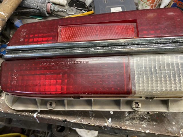
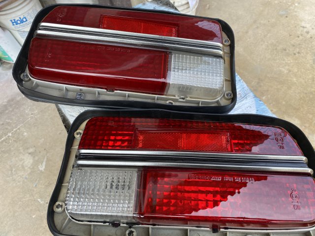
Restoring the Rear Tail Light Assemblies
A picture of the "Before" restoration of the Tail Light Assemblies.
Note: dull finish, dents and chips.
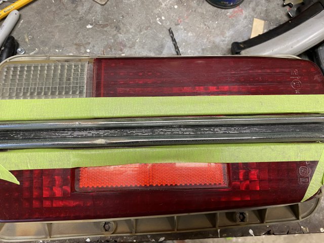
The Lens was polished with buffing wheel and chips were filled in with epoxy.
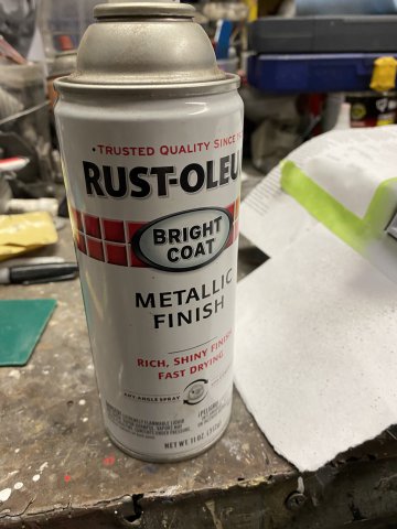
Krylon "Lookinh Glass" spray paint was utilized to provide the "Chrome Like" twin parallel bars of the lens.
To give the Tail Light Assemblies additional "POP", Polyurethane Clear was sprayed over the lens.
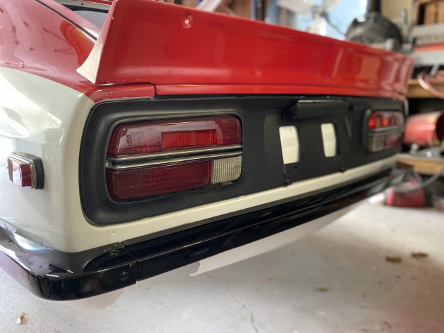
Tail Light Assemblies installed.
Spoiler Installed.
-
For instructions to construct your own Spindle Pin Removal Tool, Go to V8t forums-Gen III & IV Chevy V8- Heavy Duty Frame Rails and Connections- #9 dated January 16,2019. I bought only a few parts of Home Depot to build and construction was only about an hour.
Otherwise, a Floor Hydraulic Press could be utilized.
-
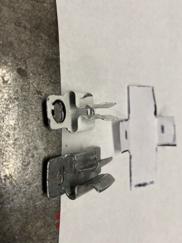
"Lost Part"
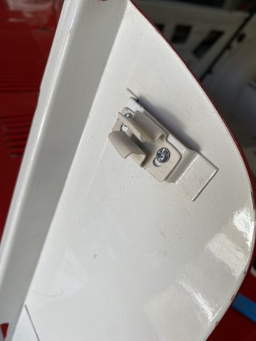
I somehow lost one of the Hoods Accessory Door Spring Latch. So I was forced to create one using the other one to copy from.
Original, the Copy and Template
It was constructed from sheet metal using pliers and a drill.
Test Fitted then to be Painted to match.
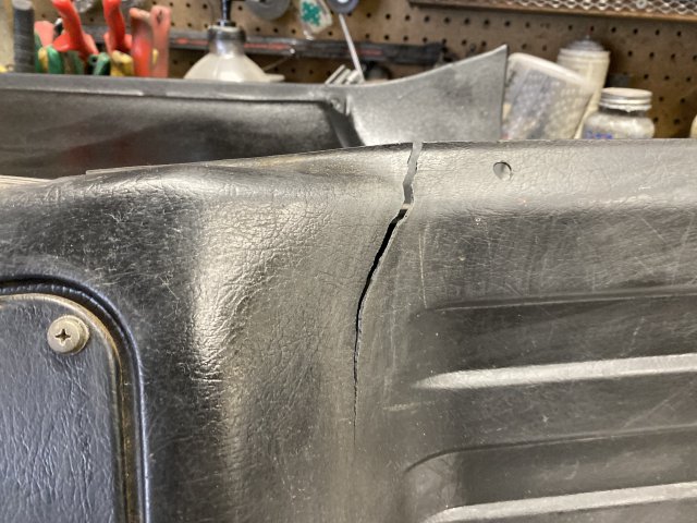
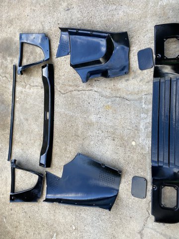
Restoring Damages Masonite and Plastic Interior Panels
cracked Masonite Panel
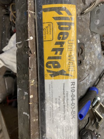
Fiberflex Rods and Fiberglass Screen Window
Mesh were used for these type of repairs.
Mesh with plastic melted over it created a strong
repair.
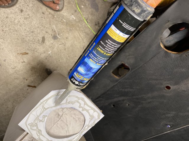
One Masonite panel was missing a large section so I glued a piece of .0025" Aluminum Sheet
to fill in the missing area. Fast Drying Epoxy did the job.
Vise grips held the patch in place until the Epoxy cured.
Note- The hole in the panel is for Radio Speakers.
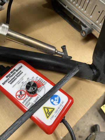
Plastic Interior Panel Repair
Big crack in Rear Plastic Panel
The Crack was aligned then "tack welded" with the Plastic welder. On the other side, Stainless Steel Mesh was covered with FiberFlex plastic rods to provide a study backing. Then, the otherside of the crack was gone over completely with FiberFlex rods too.
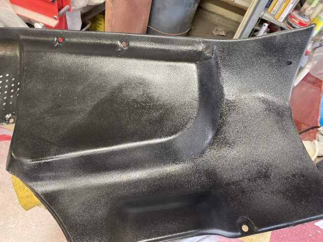
Painted with SEM TEXTURE Black paint and prep for painting.
Plastic Interior Panels painted.
Console paintedCloseup of Hand Painted Console Switch Lettering
-
I was wondering if anyone out there, knows anything about Love20bee-a custom wheel maker in El Monte, Los Angeles. He specializes
in making custom 3 piece wheels especially for 240zs. His shop was featured on Hoonigan Auto Focus on You Tube.
Toolman
His website: Love20bee.com has numerous pics of his custom made wheels-mostly JDM stuff.
-
idiot280, I don't think the Precision Weatherstripping is made with Silicone in it. But they probably coated their rubber molds with silicone for easy removal of the weather stripping. I always wipe the areas down where the adhesive is going with lacquer thinner before glueing.
The Precision Weatherstripping is well made but is "Fatter" than the original 240z one. So you might have readjust your door and hatch
latches to allow them to close. The rubber will eventually wear in. Or if you can not wait for it to wear in, construct a similar "pull cable" that I made for the doors and put heavy weight on the hatch. But remember to remove the latches so they can compress the rubber more.
. Also, if you still have problems with the weather stripping not sticking, use clamps or similar tools to hold the rubber down. Especially around the corners, the adhesive on the rubber must contact the adhesive on the body. I always check
this by tugging on the rubber after an a hour after application. If rubber loose, glue and clamp down again.
I hope this information helps you.
-
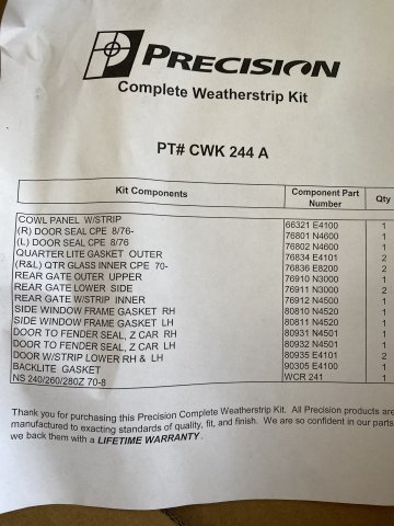
My Weather Stripping Kit from Zdepot arrived just in time. It costed about $300 but was high
quality and fitment was good.
kit parts list
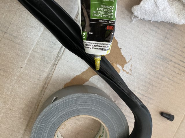
The Hatch Weather Stripping was installed with 3M Super Weather Stripping Adhesive. I found
the older yellow version to hold better than the newer Black Version.
Note-Be sure to let the adhesive to dry(5 - 10 minutes) or until "tacky". Then hold both together for
at an hour. I used masking tape and duct tape.
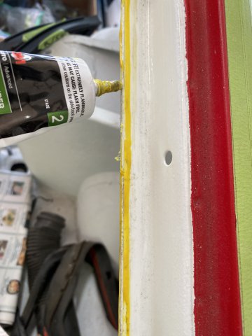
on weather stripping
on body edge then hold together.
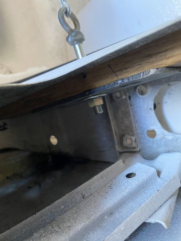
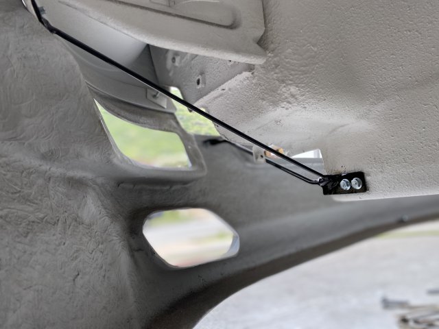
When installing New Replacement Door Weather Stripping, if you having trouble closing the door even after
adjustment, you try this tip. I rigged up a 1/8" steel cable connected to the inside seat belt mounting
hole. Put a Turn Buckle in between the mount and cable. The other end was attached to the latch side of the door. A 3/4" x 2" board was utilized inside of the door to prevent damage to door.
The operation is simple-Turn the Turn Buckle to shorten the cable. This will force the door
to squeeze the weather stripping tight. Remember to remove the latch plate on the quarter
panel otherwise maximum force will not be achieved. The weather stripping must be squeezed a lot to compensate
for the"rebound factor".
seat belt mount side
door anchor side of cable-note board inside the door
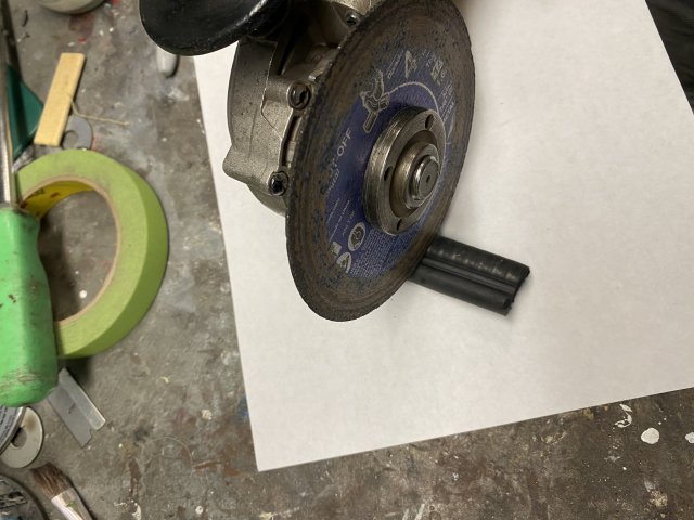
Another tip- To cut the excessive door weather stripping, a 4 1/2" right angle grinder with a
1/32" cutoff wheel was used because the door weather stripping contains a metal webbing
inside.
cross section of door weather stripping
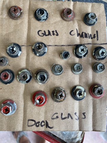
Another tip: When Powder Coating. I sometimes use a piece of cardboard to hold screw and bolts
while sandblasting.
Next to the parts, their location was written to aid
in assembly.
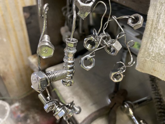
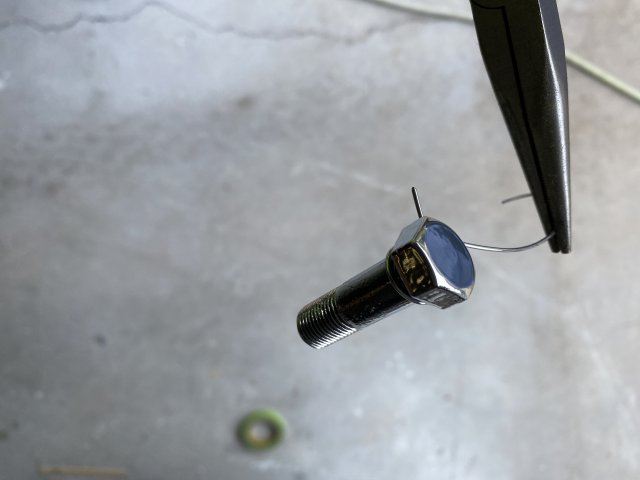
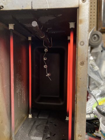
To hang screws, bolts and washers while baking the powder coat, .030 Stainless Aircraft Safety Wire
is used.
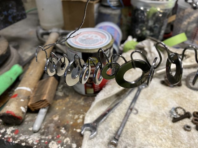
This zig zag type of hanger is utilized to keep parts apart when baking.
Rethreading of all Powder Coated items is necessary as the Powder Coating will add additional
material to them.
-
EF Ian,
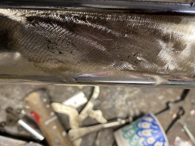
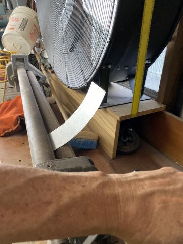
Yes, In the Old Days, rechroming bumpers was a common procedure. But now days because of the toxic byproducts and mostly the cost, only limited automotive chroming is done. You can also use a a torch and braze the holes. Then grind it smooth with 24 grit paper. The rechromers will first apply copper plating then chrome plate it. I would have powercoated the bumper but the center section would not fit in my small oven. PowderCoating powder to do this bumper would cost only about $13.
-
I had planned to assemble the Front and Rear Suspension to the Z but decided to work on the interior parts first.
Door Glass Regulator was cleaned and lubricated.
The Door Glass had a lot of Water Spots from being parked outside.
These Water Spots were removed with #000 Steel Wool and Hand Rubbing Compound.
Rub in a Circular Pattern to remove all the spots.
Looked like Brand New Door Glass.
Before Disassembly and Rebuild.
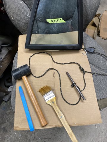
Tools used to rebuild the Quarter Glass: Plastic Glass Tool. Rubber Hammer. Tire Lube Brush. and 1/8" Nylon Rope.
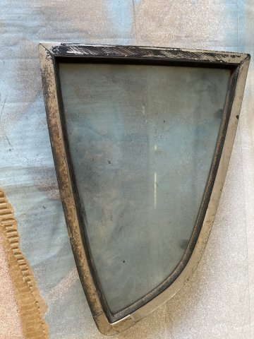
One area of reassembly was the 1/4 Window Glass Frame. Because of the New Weather Stripping. squeezing the Frame together posed a
problem. This was solved by wrapping a 1/8" Nylon Rope around the frame and 3/8" x 6" Bolt. Twisting the bolt between the rope will cause the rope to get tighter and tighter. This action will squeeze the frame together and allow the installation of the frame screws.
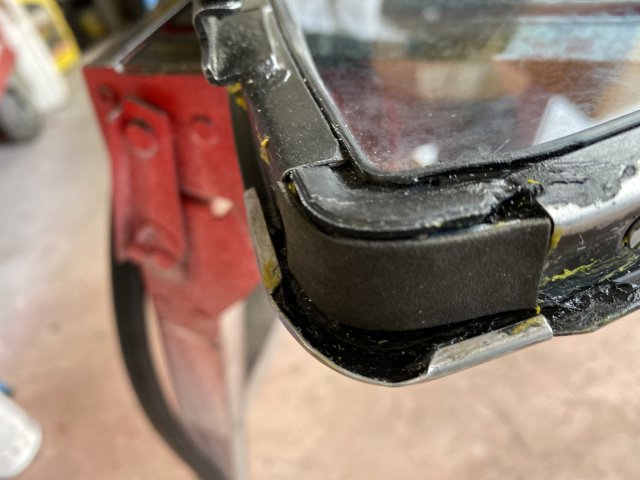
Now, check the corner of the 1/4 frame with the long ends.
Note-A strip of Rubber added to the Frame. This Rubber Strip fills the gap so the Outer Weather Stripping Gasket does not leak. Check the Old OEM weather stripping. It
probably has a similar rubber strip that is not included with the replacement weather stripping.
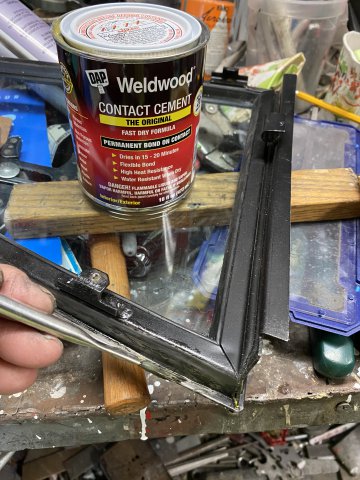
The Outer !/4 Glass Weather stripping was attached with Contact Cement , Use a Acid brush to apply the Glue. Apply the Contact Cement to Both Sides (gasket and the Frame). Make to allow the glue to dry for 10 to 15 minutes before sticking them together.
Wrap the1/8" Nylon Rope tightly again around the Weather Stripping and then knot it so it holds till the cement dries.
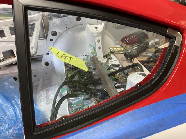
Installation of the Assembled 1/4 Glass on the car usually requires two persons. As the Glass must be pushed both rearward into the body and
inward to attach the mounting screws.
Installation Complete.
The 1/4 Glass Frame was painted with Sem Products Trim Paint Black to match the Race Car Theme.
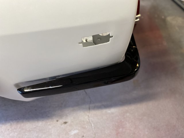
In this case, the Bumper Guard and Bumper Rubber Strips Holes were going to be welded closed to provide a more Clean Look.
!/8" Steel Plugs were cut and fitted into the holes before welded.
Welded Holes after Grinding
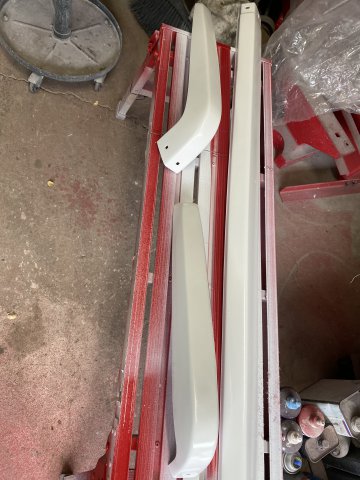
Bumper Parts Poly Urethane Primered.
Single Stage Black Polyurethane Paint was used to paint the Bumper Parts.
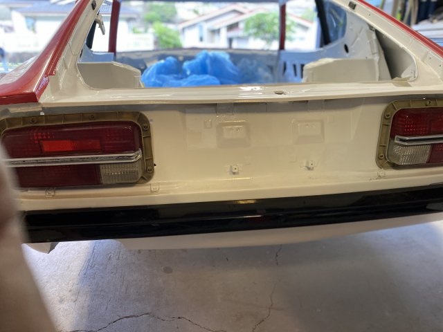
Bumper Installed on car
Side View
Center View
-
Thanks, Guys
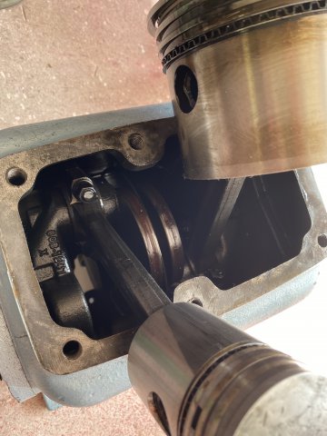
After getting the Air Compressor parts, I did a complete overhaul on the FS Curtis D96A compressor pump.
Replaced Intake and Exhaust Valves, new Head Gasket, new Piston Rings and new Con Rod Bearings.
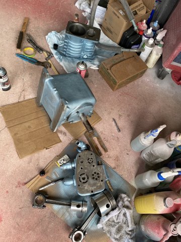
After the Compressor was repaired, The Greddy Rocket Bunny Flares were installed. On Ebay, Z Spec Design had their Rocket Bunny
Kit Installation kit for $90.
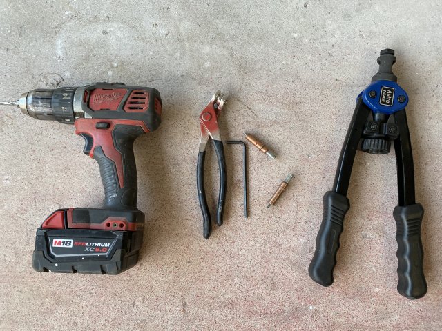
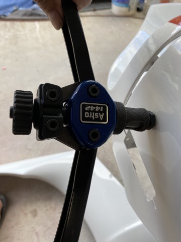
These tools were used to install the Flares.
The Cleco Clamps were utilized to hold the Flares in place while drilling.
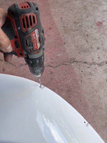
The Drill drilled the mounting holes into the Flares. Also, it drilled the Body side for the Threaded Nutserts.
Drilling the Flare
Drilling Body for Nutserts.
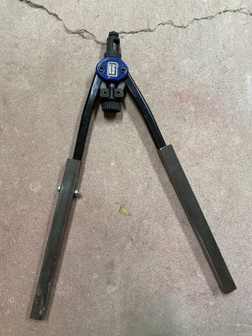
I added a 11" extensions of 1" square tubing to the Nut Setter( lengthening its arms gave it additional leverage).
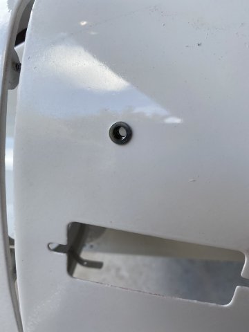
Threaded Nut installed.
I recommend all insets be rethreaded. Sometimes the inserts are distorted during installation.
Installed
The Paint and Materials for this car was about $2000(Jobber Cost). Sherwin Williams Ultra 7000 Poyurethane paint(Basecoat) and CC2000 Clear Coat were used. I also used the 3M TRiZ Sanding system which consists of P1000, 1500 and P3000 Velco Sandpaper was utilized too. This method reduced the polishing times drastically.
Next thing to do: Installing Front and rear Suspension on the car. Happy Fourth of July Holiday to everyone!!
-
The Whole car was recoated with the Final Poly Primer then completely block sanded again.
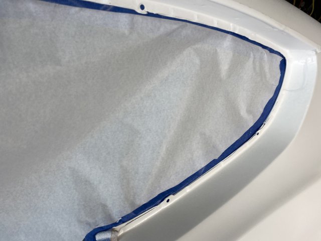
After the Final Sanding, masking of the car was next. As the car had no front windshield, door glass and rear hatch installed, there was nothing
to tape to as in regular masking. So Back Masking was utilized. Back Masking is masking from the rear or from the inside out.
To begin with, 3" Masking Tape was applied around the edges of the Front Windshield Opening(from the inside) so the sticky side of the 3"
tape protruded outward about 1". Two or Three Vertical 3" Back Tape were added to provide support for the Masking Paper.
Add 3"Horizontal stripes of tape on the
Vertical Tapes to make them tight as possible to support the masking paper.
Masking Paper was added from the top edge of the Windshield to the bottom edge of the windshield. Make the masking paper a little larger. Lay the masking paper to the tape on the windshield edges and the vertical tapes. Don't press the tape and masking paper together yet. Using a new razor blade to cut the excess paper allowing for 1/2" of sticky 1" tape exposed.
When you finish cutting the excess paper off, apply 3/4" masking tape to the 1/2" area. So your masking paper will squeezed between the Back Masked
3"tape and the 3/4" masking tape and be really secure.
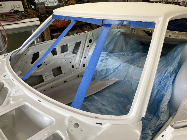
This view shows the Masked Widshield looks like from the inside.
The Door Widow and Rear Side Glass was also masked with Back Masking.
Since, the Rear Hatch was a large area to mask, a slightly different procedure of masking. I used a Welders Tie Wire to provide more support
for the masking paper.
Welders Wire
A piece of cardboard also added to give support when pressing the masking paper and tape together. Otherwise, since the hatch area is closed
off at the back, you can't stick your hand under the masking paper to press the masking paper and tape together.
Note-The Hatch edges are Back Masked
as the Front Windshield.
The Engine Compartment was masked using the same as the Rear Hatch procedure.
Used a X pattern with the Welders Wire in this case mainly because the availability of body holes.
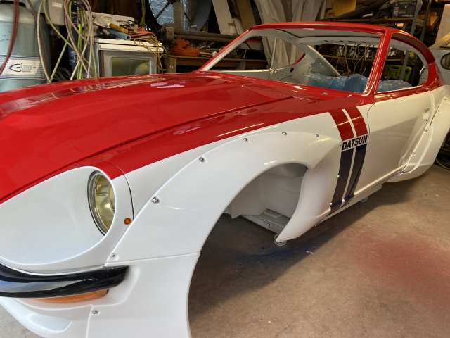
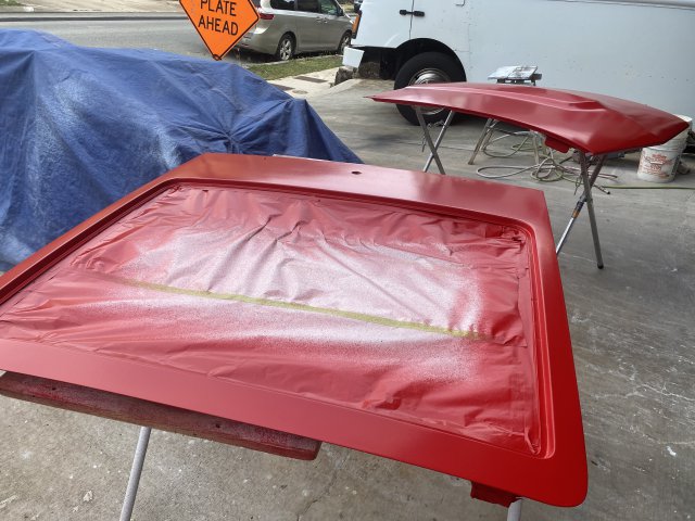
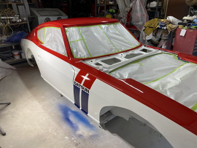
Now, I went about to mask the car for a TWO COLOR paint job.
Note-Blue !/4" Pin Stripping tape was
utilized to produce a sharper line than regular masking tape.
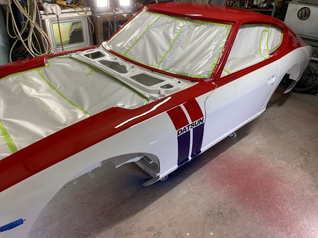
Red Top
White Bottom
Rear Hatch and Hood being painted.
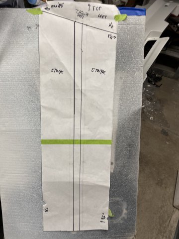
Made a Paper Template for Racing Stripe.
Flip Template over for the Opposite Side.
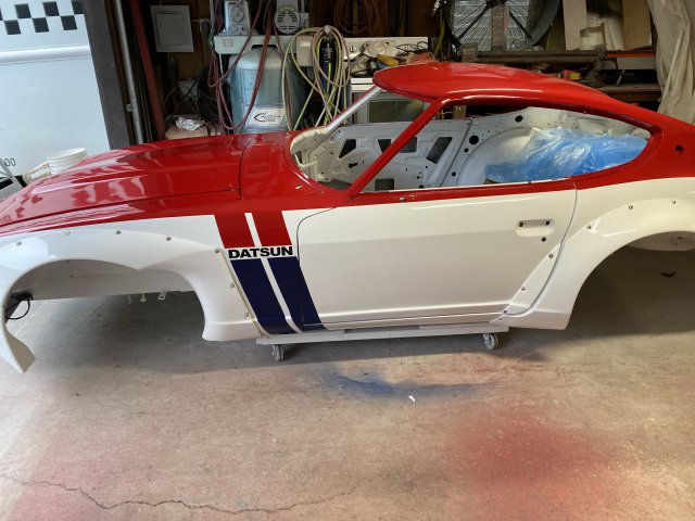
Racing Stripe with Datsun Logo
After Striping and Clear Coating
Rear View
Side View
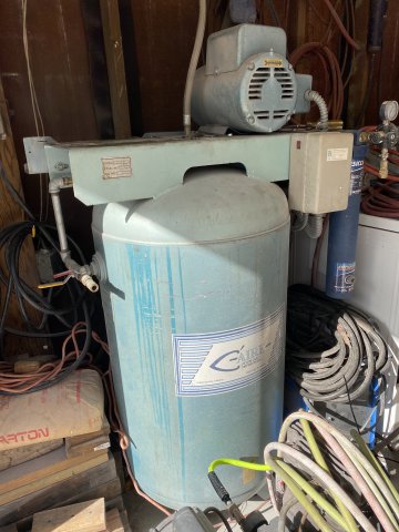
Unfortunately, after I clearcoat the Z, my garage 7 1/2 HP air compressor broke down. When I tried to start it the next morning, the air compressor
would not build pressure. Lucky me, it did not happen when I was Clear Coating. So any way, I took the compressor pump apart.
So, Come Monday, I will order the Master OverHaul Kit which has new piston rings, rod bearing and valve parts plus gaskets and various
seals. Then I can Clear Coat the Flares, Soiler and Front Panel.
-
Nelsonian, Thanks for the tip. I will post my solution when it happens,
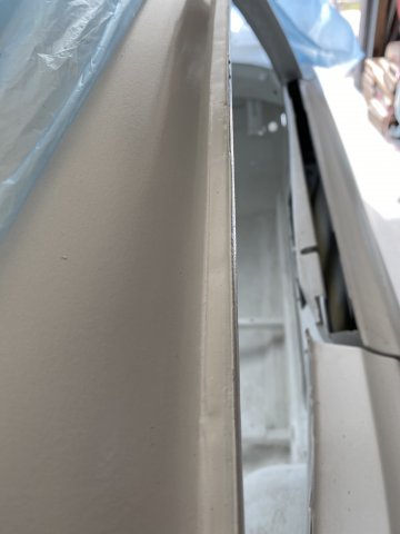
Here is a pic of the Right side Rain Gutter finally primed.
Came out real smooth.
I had constructed a frame to hold the Spray Booth Exhaust Flilters but got rid of it as it took up too much space. So I came up with a much
more simplified method to the filters. I just screwed a dozen clothes pins to the garage door.
Inside view
Simple and but Effective.
Outside view of Exhaust Filters.
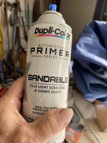
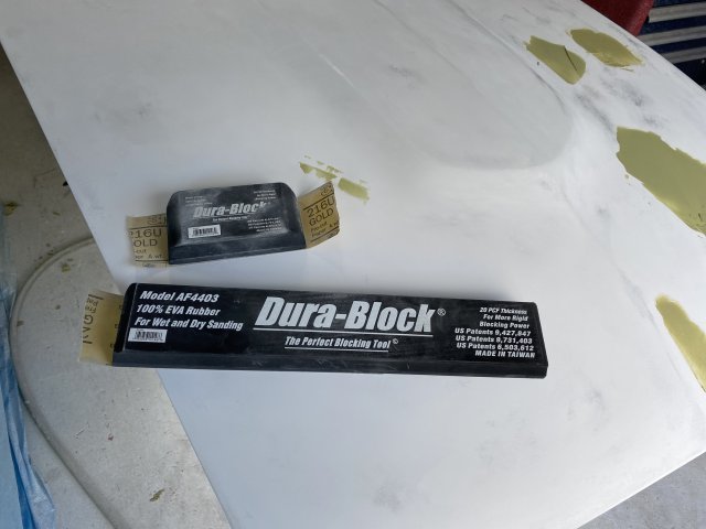
Now, Back of Body Work: I utilized Black Primer in a spray can to locate Low Spots in the bodywork.
Only a Light Coat of Black Primer Spray is necessary,
Use Sanding Blocks( short and long) Long one is for large areas (roof and hood). Start sanding in a Diagonal Direction then sand over the cut
in Opposite Diagonal Direction to create a "X" Pattern. Using this method, the low areas will show up as dark spots.
Hood with the Low Spots covered with a thin layer of Body Filler.
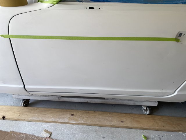
To Restore the Body Lines on the Doors, Apply 3/4" Masking Tape with its Lower edge run the new tape top on the Body
Line. When you finish sanding along this edge, you end up with a nice straight body line. The 240z body line have a sharp edge so
you cut the sharpness with the sanding block.
creating a Body Line.
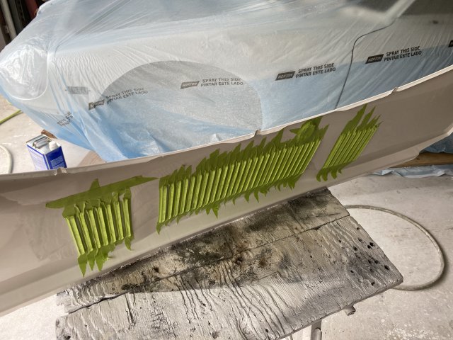
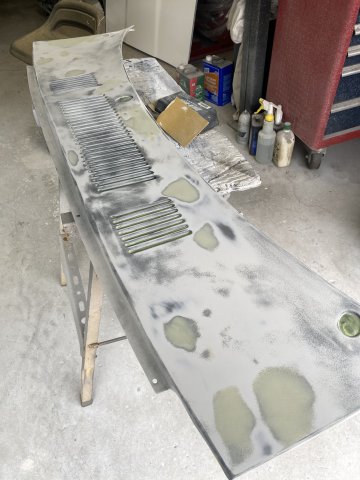
The Cowl Panel sprayed with Low Spot Finder,
Cowl Panel masked to prevent overspray.
Cowl Panel with Low Spots filled.
R/Quarter Panel and Door Sprayed.
Right Fender ready for more sanding.
This fixing low spots and spraying HD primer filler can go on for a couple of times. The 240z thin Sheetmetal (.023") body lends itself
abundance of small dents.
As a lot of you are "stuck at home " during this Pandemic and can't work on your 240Z, here is a solution:
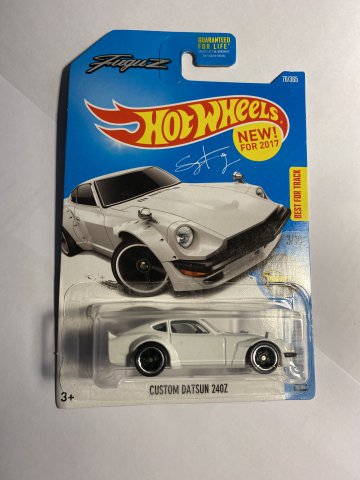
Hot Wheels 71 Datsun 240z Rocket Bunny car.
Hot Wheels has several versions of Datsun 240z -completely stock to Radical Race Cars. Collect them or modify them.
I will modify mine and post my progress.
-
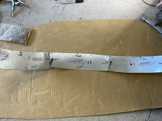
A Reinforcement was constructed for the Front Rocket Bunny Bumper. It was made of 1" x 1/8" square tubing with 3/16" bumper brackets.
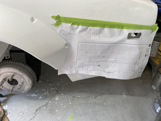
First, a template of the reinforcement was made out of cardboard.
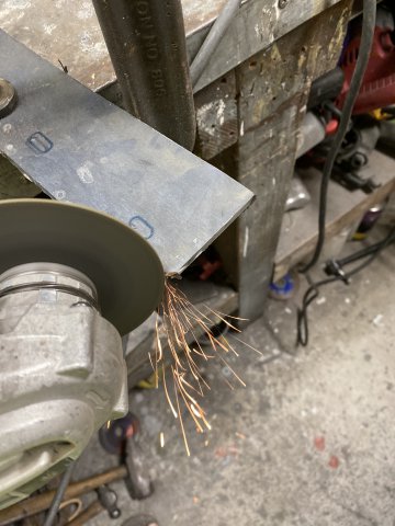
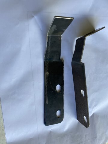
Bumper Brackets were made 3/16" Plate Steel and cut out with a 4 1/2 Angle Grinder.
Pics of both Front Bumper Brackets
Pic of Bumper Reinforcement Bar
Reinforcement Bar mounted.
Attempts to use Insulation Foam to attach the Fiberglass Bumper to the Reinforcement Bar failed. The problem was the difficulty to
get the Foam evenly between the Bumper and Reinforcement. Because the Corona Virus, the solution to this problem will have to wait
until more stores open up.
Unsuccessful for now!
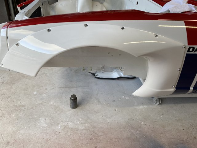
I constructed Four Flat 16 Gauge plates of 16 gauge Sheetmetal to fasten the Front Flares to the Front Valance Panel.
Note: The Plate is folded on the outside edge of the the Plate. This Fold
greatly increases the strengthens the Plate.
A Right Angle Die Grinder and a Tight Fit Drill Attachment were used because of the tight space.
Inside Front Wheel Housing, pic of the Reinforcing Plates "sandwiching" both fiberglass parts together.
Outside View of the "sandwiched" parts
The Roof Rail Gutters were seam sealed with Fastline #FS2SL. It is a self leveling sealer and made for car rain gutters. Working Time is 10 minutes so you got to rush. It can be painted in 30 minutes and fully cures in 2 hours. It flows like water so don't forget to "dam" both ends of the gutter.
The next day, the sealer flowed so much that I had to apply a second coat.
If necessary, you can sand the sealer smooth.
The Front and Rear suspension were removed to prevent the parts from overspray even with masking. The plastic curtains opened up
and work area was cleaned in preparation for car painting.
But, there is a lot of preparation(a whole lot of sanding and masking) before actual car painting.
-
The Left Rear Flare was mocked on by creating a template of the completed Right Rear Flare.
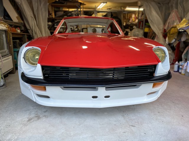
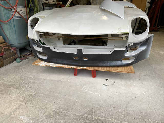
The Rocket Bunny Front Valance Panel mocked on the car,
.
Pictures of the Greddy Rocket Bunny Front Valance Mounting points.
Note-the original holes were only 3/16".
It was at this point that I decided to add additional mounts from the car frame to fiberglass front valance panel. Otherwise, it would not be
strong enough for even a street vehicle.
The mounting brackets would be constructed with 1/4"solid steel rod and 1/8" steel plate.
Center mount was mounted to the frame extending to center of Valance Panel.
Mig Welding of the side Valance Mounts
The Valance mounts would extend to both L/R sides of the grille and marker lamp areas.
Left and Right Mounts before Powder Coating.
Left Valance Mount powder Coated installed
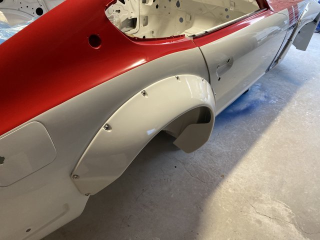
The Front Flares were mocked on using Cleco Pins.
Inside view of Left Flare
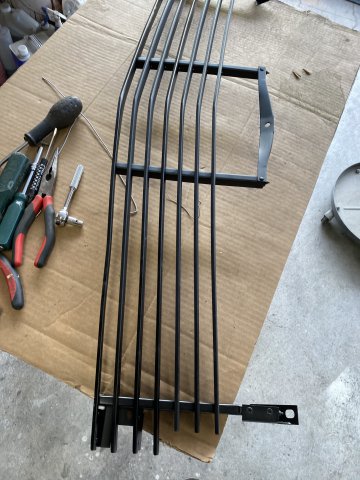
The Grill was disassembled for sand blasting and powder coating.
The Grille consists of 6-Horizonial grille blades, 4-Vertical mounts and 4-3mm x 8" Long Bolts. So I took a lot of pics so I would not
forget where everything went.
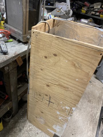
As the Grille is about 4 feet wide, it would not fit in my Powder Coating oven. So I constructed 2' x 2' x 4' box out of 3/4" plywood.
It was lined inside with Aluminum Foil to retain the heat.
A 2000watt Infared heat lamp provided the heat.
Powder Coating the Grille parts.
The Grille was powder coated with Flat Black Powder then assembled.
-
I had planned to work on installing the front suspension parts on my Z but I discovered that my supply of Gold powder was almost gone.
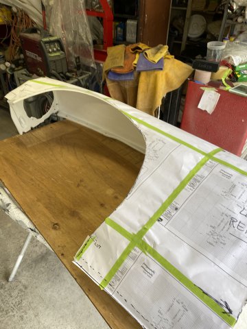
So while I waited for the Gold Powder to arrive, I decided to finishing cutting the Right Front fender for the Rocket Bunny Flares. Like the Rear Flares, I made a Template of the already completed Left Front Fender.
Note- I use almost all the fender edges( top, back, front and bottom) to create the
template. The more reference points that you use, the more accurate the template will be.
Side view of template
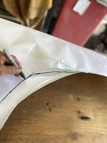
Put template on the Right fender then
Transfer the trim lines using a Black Marker pen.
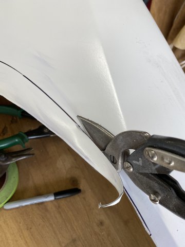
A Tin Snips was used to trim the fender. It was used as cutting thin metal like the front fender, vibrates a lot and making it hard to control.
Note- make sure to grind all trimmed edges to prevent future sheet metal cracks.
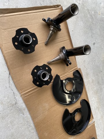
Next thing to do was to clean all of the Front Suspension parts in preparation for painting or powder coating. The rear stub axles were prepped at the same time to conserve paint materials.
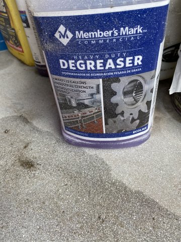
All the parts were first cleaned with cup wire brush on a 4 1/2 electric grinder to remove the heavy grease, dirt and paint. Then a Heavy Grease Removal soap ( was used straight without dilution) was used. First, with the parts cleaning brush then with a air solvent gun shooting the degreaser( now diluted) to get those hard to get to areas.
Blasting away
Stub axles after paining with Black Polyurethane paint. Note- the rubber joint
boots were masked off otherwise the axles would have been disassembled to remover them.
The other suspension parts after Polyurethane Painting.
Before Powder Coating
After Powder coating
A flange bolt powder coated
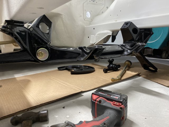
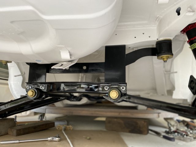
Front crossmember mounted
Note- new Camber adjusting bolts were installed.
Front to rear view of Front Suspension. Note -The Powder coated parts gives
a nice contrast with Gloss Black suspension parts.
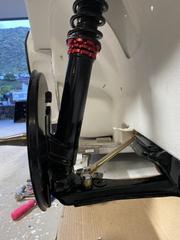
Side view of the Right Side Suspension
It took a lot of cleaning, grinding, painting and powder coating but I think it was worth it.
Next, installing the Wheel/Tire Fitment Tool on the Front Suspension to check it out, is next.
-
 1
1
-
-
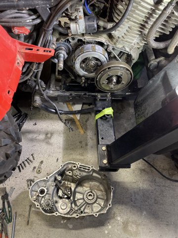
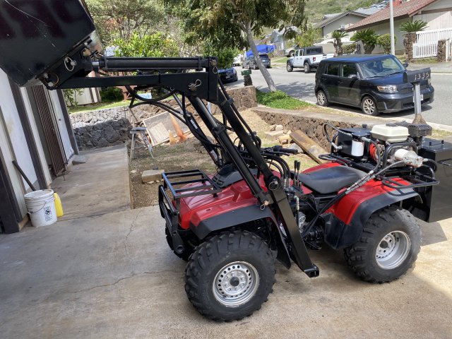
Sorry for the delayed reply. My 87 HONDA TRX350 ATV transmission shifter was jammed in gear. As it required me to split the outer left and right cases, the repair took two days to complete.
It had to be repaired as it occupies the garage opposite of the 240z and there would be no space to work.
This Front Loader Conversion to my Honda ATV was done before I started the 240Z restromod. I scratch built on a 87 HONDA TRX350
ALL WHEEL DRIVE ATV IN about a year ago. It can lift 400lbs in the loader bucket and has a 30 gallon water tank in the rear for ballast. The conversion was made to be Bolt On Accessory and can be removed in about 30 minutes.
Now back to the Z Project.
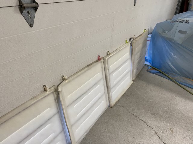
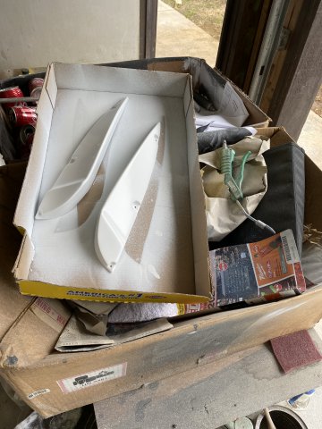
All Four of the Flares were painted inside and out with Polyurethane Primer.
Had problems removing silicone from the mold release on the flares. Had to use Wax and Grease Remover and HD Water base soap several times to get the silicone off.
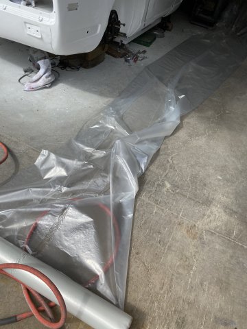
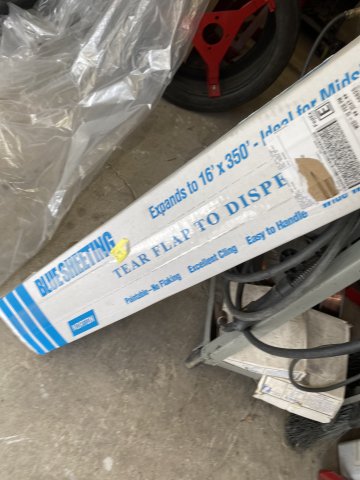
Due the Windy conditions, I had to paint the parts in garage so had the cover the 240z with Plastic Sheeting to prevent overspray.
The Plastic Sheeting can be gotten from automotive paint suppliers.
Wheel Fitment Tool
Finally get to use the Wheel Fitment Tool that was made coupe of months ago.
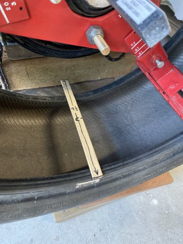
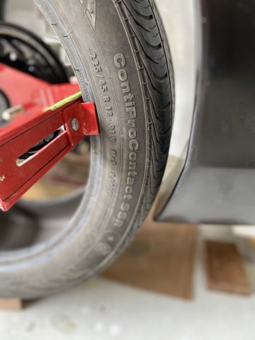
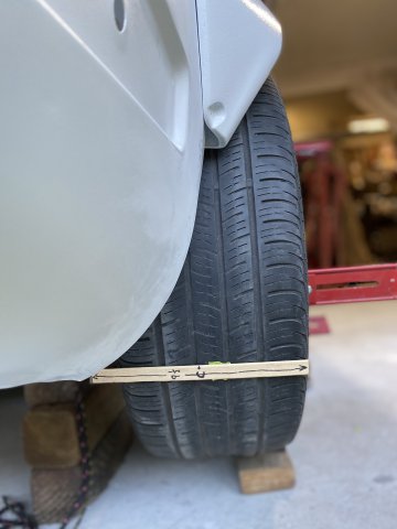
This was the closest size tire that I could find to use-225x 45x 18. The wheel that I will be simulating is Rota RKR 17 x 9 1/2 with 20mm negative offset. As the sample tire is not large enough, it will be used with the majority of the tire will be facing outward to check fitment. As I running lowered coilovers, the inner clearance with strut is not a problem.
First, install the Fitment tool with two lower legs set to 18 " diameter and third leg retracted. Now, adjust the two lower legs tire width adjustors to fit securely.
Now, Adjust the upper third leg to obtain the 18"diameter and adjust the tire width adjusters for a snug fit.
The only wheel that I found that had specifications came close was ROTA RKR 17 x 9.5 with -20MM offset.
I put its specifications on a wooden paint mixing stick.
Remember that this tire is only 18" so the 9 1/2 tire will stick more inward.
This stick show the wheel offset. The "C" line indicates the center line of the Rota wheel.
The inner end of the stick indicates the width of a 274/45 tire.
Front tire clearance shown
Front to rear view
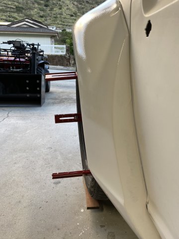
Side View of the Wheel/ Tire Fitment Tool on the car. As the car is on a dolly and there is almost no weight in the car, something had to be done
to set Ride Height. So I removed the upper strut spring section to allow upward movement of the suspension. I set the ride height setting the center of the wheel hub to the lower body line of the car. From most pics of street driven lowered 240z cars, the center of the rear hubs were in line with the body line.
This is not perfect way but I think it is close enough to demonstrate ride height until I can actually load the suspension after the complete swap.
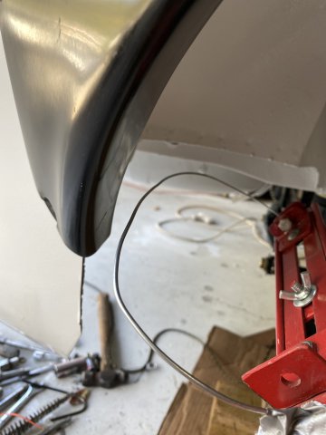
For those of you, that wanted more tire fitment information, I bent a 1/8" wire shaped to match the tire cross section that you wanted to check.
In this case, a 274 x45 tire cross section was created and bolted to one of the wheel legs.
.
You just rotate the simulated tire cross section to check any clearance issues with body and strut.
Check Front Clearance of the flare.
This rear view demonstrates what a 274 tire would look look like.
Remember the 275 tire would extend to the end of the stick or about a inch more inward.
The next thing to do is to put the Tire/Wheel Fitment Tool on the front suspension and see what tire/wheel combination
could work on there.
-
Rear Suspension Overhaul:
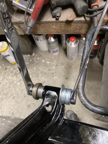
A Threaded Steel Rod with nuts and assorted washers were used to install rear control arm outer bushings.
This method was used because although slow, it has less chance of damaging the
steel metal bushing housing on these control arms.
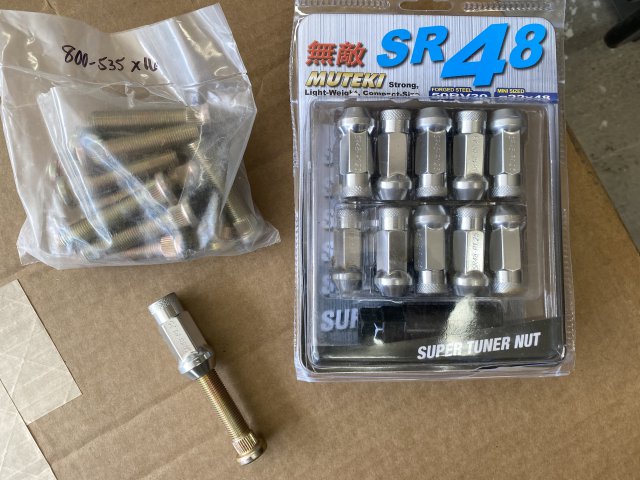
Ordered ZDepot 50mm extended wheel studs and Muteki extra long wheel lug nuts from EBAY. They maybe necessary to gain proper wheel fitment later.
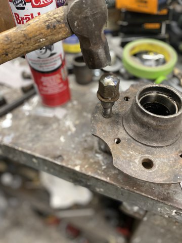
The old wheels studs were removed by hammering them into the large metal tube.
Hub parts were powdered coated.
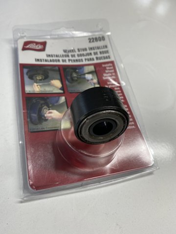
Lisle Tools Wheel Stud Installer only requires a 1/2 impact gun and lug socket to install the new wheel studs.
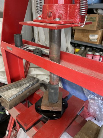
The Hub Outer Bearing was pressed on the hub.
The Outer Hub bearing was then packed with grease. The whole assembly was pressed into the strut housing.
Now, by looking into the inner bearing bore-check the two casting cutouts to determine if the bearing is properly seated. After
which. the bearing cavity and spacer is packed with grease. I used a paint paddle to spread the grease into the cavity.
The Inner Bearing(non sealed one) is packed with grease.
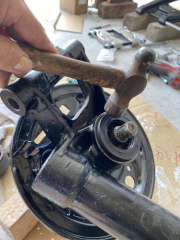
To install this bearing, you can use the old bearing to tap the new one in. Don't worry the old one won't get stuck in.
Keep tapping it until a solid feeling and sound occurs for proper seating.
id
Coat the inside of the seal with grease especially the seal lip. Tap the seal with hammer( can use old bearing also) to about 3/16" below edge.
Then, the flange. washer and locking nut are installed.
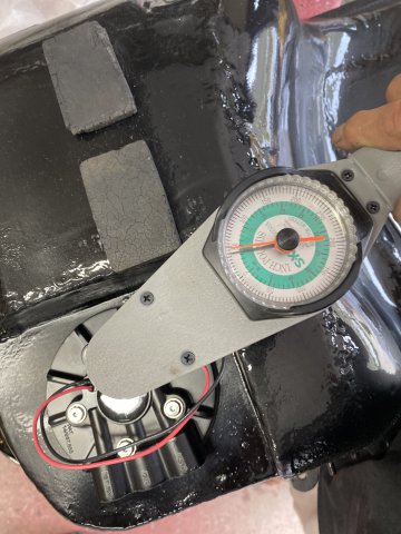
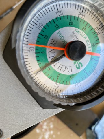
A Dial !/2 Torque Wrench was used to torque the Locking Nut. Specifications call for 180 to 250FT LBS. The reason of the range is the Bearing Preload cannot be determined by Foot Pounds alone. So you slowly torque to 180 ft lbs then check turning torque and keep doing this till everything is right. The Hub Shaft nut turning torque is about 4 inch pounds. The shaft endplay is 0 to .0059. You will need a Dial Indicator to do this but not necessary. So you try to achieve all these parameters to get a accurate bearing preload.
1/2 Dial Torque Wrench
A Dial Inch Pound Torque Wrench checking Turning Torque( about 4 inlbs)
A Dial Indicator can be utilized to check for 0 to .0059" End Play
After completing Bearing Preload, I flattened the Locking Nut tab to prevent the Hub Nut from loosening.
Next, the Rear Flares will be attached. The Wheel/Tire Fitment Tool will be installed to check fitment issues.
-
Richard, Thanks for complement.
The cowl area was masked for seam sealer spraying for added protection.
Sem Products Sprayable Seam Sealer Using Sem Sealer Spray Gun
Central cowl area sprayed
right side of cowl
Left Rear Wheel Housing interior area sprayed.
Seam Sealer was sprayed in between the quarter panel and wheel housing area( the patched area) too.
Note-the 3/16" steel rod between the quarter panel and wheel housing can be seen.
This view shows seam sealer coverage on the inside of the front of the wheel housing.
View of the bottom of the fuel filler area sprayed.
Upper area of the fuel filler area. Note-the back side of the fuel filler compartment was also sprayed.
The Right wheel housing was sprayed with White Raptor Bedliner after Fusion Seam Sealer was applied over all patch seams.
Front view of Right Wheel housing sprayed.
Right rear Wheel housing sprayed.
Pic of my garage work area.
Suspension parts painted with Gloss Black Single Stage Polyurethane Paint on my driveway.
R200 differential was also painted.
Rear Strut housing painted.
Next thing for me to do is replacing bearings and bushings suspension parts and the reassembly begins.
-
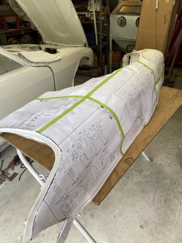
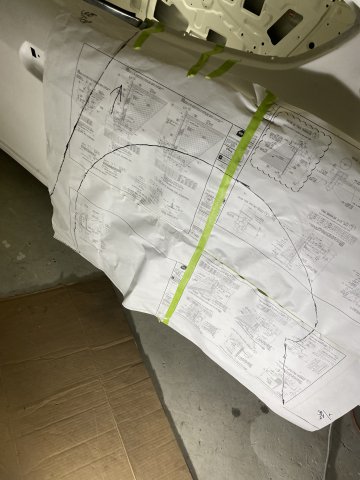
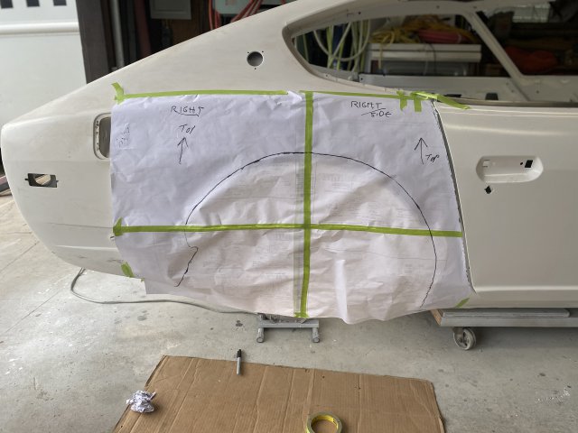
Replicating the Left Rear Wheel Housing to the Right Side.
To do this task, will require making a paper template of the newly modified Left Rear Flare opening. A large piece of paper was placed
over the L/R flare opening. The major reference lines to be traced are: #1 The Front Edge of the Rear Quarter Panel. #2 is the Wheel Well
Opening Edge.
The distance between the Top Center of the Wheel Opening to the one of
body holes for mounting the Rear Quarter Glass. The measurement will be the height of the flare opening.
You may have to darken your Guide Edges if their ink is not visible on the opposite side of the template. Remember you have to use the opposite
side the template for the correct orientation. Using the edge guide line and height measurement to align the template on the Right Side.
Make sure to securely tape the top edge of the template to the quarter panel as you don't wanted the pattern moving.
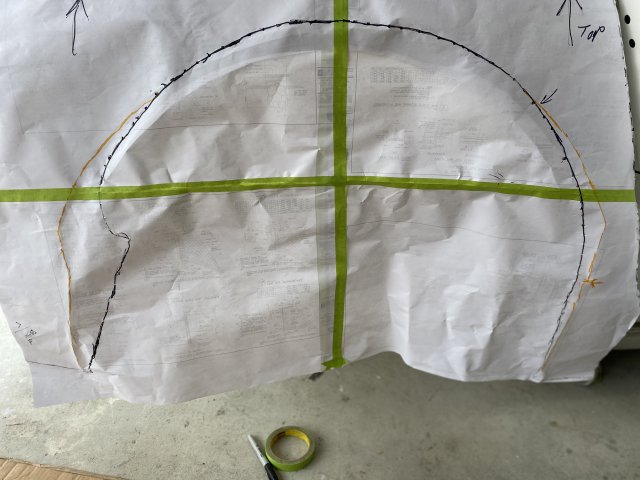
The Orange Lines in this closup show the areas to must be filled in because overcutting from previous flaring. This provides pattern
for the filler panels.
Creating the Rear Filler panel. Note- guide lines help to keep filler aligned.
The Front Filler Panel being created.
Pic of the Inner Wheel housing to Quarter Panel Filler patch Template.
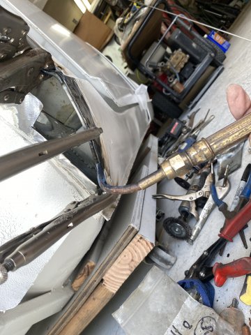
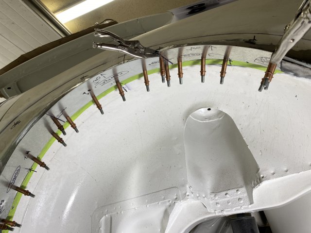
To make this Flare Opening a little easier to weld the quarter panel and wheel housingtogether, 3/16" Steel Rod from Home Depot( $13 for 8Ft)
was used. The rod would weld between quarter panel and wheel housing filler. It prevents burn through especially with .023 sheet metal.
On the Front Side of Quarter Panel (Dog Leg Section), there are some curves in the panel so you must bend the rod to follow the curves.
That task is accomplished by holding one end of rod with vise grips and using a torch to soften the 3/16" rod. Then bending the rod until the
required shape is obtained.
Note-I have used this technique of welding round steel rods around flare opening on many cars. You can use 3/16" to 3/4" steel tubing or even brake lines to outline the tire openings. But solid steel rods don't kink like fuel lines would This method really reinforces the edge and prevents tire damage in case there is contact.
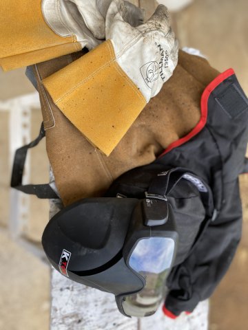
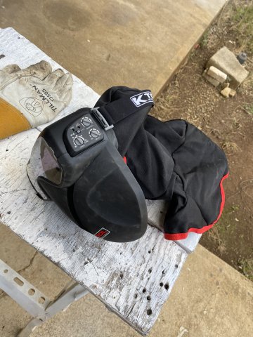
For those of you who are tired of getting burnt by hot sparks while welding in confined areas, I would recommend getting this welding gear.
The Tight Fitting Welding /Grinder Automatic Darkening Hood Gear. Regular Welding Helmets were never made for tight confined areas.
After trying this welding gear at the Sema Show, I ordered one for myself.
The Rear Filler Patch mig welded in place.
Pic of the Front Wheel Housing patch template.
This patch was created using Left and Right Cut Tinsnips. They make cutting curves
easy.
Front patch after hammering and metal shaping.
The area to be filled in. Patch test fitted.
Top Wheel Housing Filler patch
Rear Wheel Housing Patch
Rear Housing Filler patch
The Next Thing to do is spray Raptor Bedliner over the inner wheel housing for extra protection. Then Top Coat it with Single Stage Polyurethane paint.
-
Thank you Nelsonian, Here are additional pics of flaring modifications.
After sealing the inner top section of the wheel housing, area was painted with polyurethane paint.
Bottom view of wheel well housing after
painting.
Overall view of rear flaring modifications
-
Left Front Fender modifications for Greddy Flares.
After placing Rocket Bunny flare against the fender then mark the area to be removed with a black marker pen.
A Electric shears was used to cut the major removal cuts.
Always cut carefully to prevent "over cutting too much".
A Hand Nibbler was used in the Finishing Cuts.
The Finished Product
Rear Wheel Housing Modifications for the Rear Flares-
Like the Front flare. the Rear Rocket Bunny Flares are mocked against the existing quarter panel.
The Outer edge of the flare is marked
with a Black Marker Pen.
In my case, I had already removed the original wheel opening edge when I constructed metal flares previously, there was a little less
of the quarter panel to remove.
Bottom view of the wheel well(looking upward from the ground)
As the photos show the gap between the quarter panel and wheel housing was only about 3/4". So I could have just squeeze both panels together
and mig welded them together. But I decided to cut an additional 3" higher to give more tire clearance and allow more body drop. Better to do it
now instead of later.
Side view of additional cutout.
But now, the gap between quarter panel and wheel housing increased by about 2 1/2". So fillers had to made to fill these gaps.
Patch being mocked up.
The Sheetmetal Roller was utilized roll the metal to match the wheel housing.
making gap fillers
Overall view of the gap fillers
An Air Punch/Flanger is used to flange the edges of the fillers to make the filler surface smooth and stronger.
Cleco pins and vise grips hold the gap filler plates in place for welding.
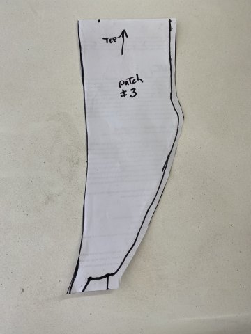
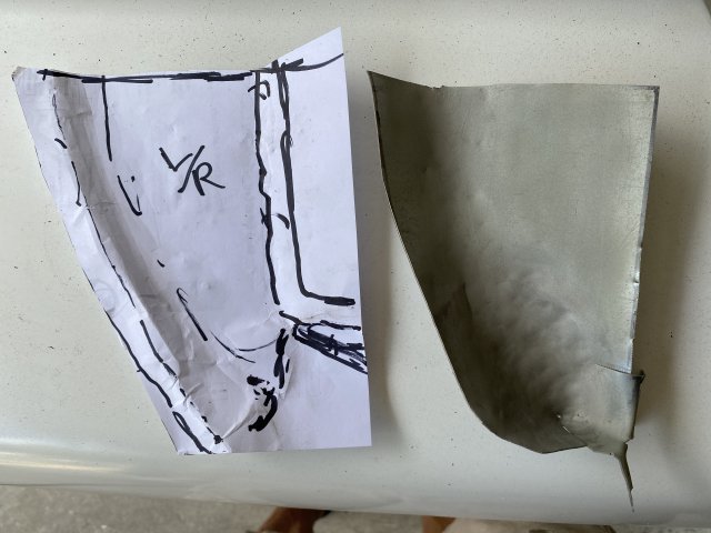
The front of the Left wheel well housing needed a patch so a paper template was created.
Note- the bottom of this patch had to be
"rolled over" by making a slit on the bottom then hammer welded the slit closed.
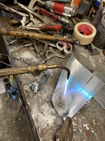
The patch started as a flat piece of 20 gauge sheet metal that heated with a torch to soften it.
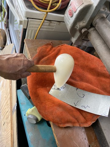
Then was hammered with a Shaping Hammer on a Leather Shot Bag to shape the patch.
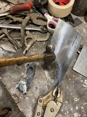
Additional pounding with a Ball Peen Hammmer.
The Patch fitted into place then tack welded in.
The inside portion of the wheel well patch was covered with Fusor Seam Sealer.
Inside of the wheel housing, EverCoat Epoxy Seam Sealer was applied over all welds and all seams. Polyurethane paint will be spray painted over all of the repaired areas. The inside wheel well areas will also be covered with
Urethane BedLiner for additional protection.
.JPG.a56d1f6d6f6e913c2f489971abf3e5a0.JPG)
 Left to Right- Return Line, Fuel Feed Line and Vent Line.
 View of upper side of Fuel Pump
 Using a Vise Grip, the Float Arm was bent to clear the Surge Tank Walls. The Float Arm can be adjusted further after putting Fuel in the Tank and comparing Fuel Gauge reading,
.JPG.fd2b715591dc548c75cad148024f5fd1.JPG) This Filter
This Filter
 It was made of 1/8" plate Steel.
 Start by slowly unwinding the coil slowly keeping the roll as straight up and down as


 This cabinet is twice as large and has top and side access doors. Plus it also came with a 4 foot high dust vacuum.

 Note-Remember the Pads positions.
 After Blasting, the dents were more visible.
 After cutting the tank, a patch was created to repair this area.
 Visegrips and Cleco Pins hold patch.
.JPG.57bf65d14bbbd8a63e47f9479c1e2d33.JPG) getting ready to weld
getting ready to weld
 after Brazing.

 Leaks are easily found with this method.
 Bottom of tank after KBS Sealer install
 Upper side

 All openings first plugged up.
 Then, Smoke is pumped in and for any smoke leaking.
.JPG.cda69d167d97fcf82057a23562158a97.JPG) Epoxy Urethane Primer was applied.
Epoxy Urethane Primer was applied.
 Bottom View-after Urethane Black painting.
 Side View
.JPG.da390671cb21619985b9de38d215c0c2.JPG)
.JPG.f1648d250be40505171582e34087fdc7.JPG) It is a very compact and well build unit.
It is a very compact and well build unit.

.JPG.cf9efcc57656d921479fc8723dbb9bf9.JPG)
 Disassembly, inspection and relubed
 All parts were painted with Black Single Stage Urethane paint
.JPG.4893b8b331cb1491811c502680748c93.JPG) The Gas Pedal Bracket was left as it depending on LS Electronic Pedal Assembly.
The Gas Pedal Bracket was left as it depending on LS Electronic Pedal Assembly.
.JPG.1c4451fe1241d18c3233a8569476749c.JPG) All Lines were wire brushed, primed and paint with Single Stage Silver Paint.
All Lines were wire brushed, primed and paint with Single Stage Silver Paint.
.JPG.4707c15b17bd4cee9503332f00a93f00.JPG)
.JPG.ed4246acaf91e98a0b1b95d19be58655.JPG) Cap with hole cut on top
Cap with hole cut on top
.JPG.26313e5fef751346487b455405f2423a.JPG) From Techno Toy for about $1200
From Techno Toy for about $1200
.JPG.ab40abd607e8920f6706e0f16d03d063.JPG)
.JPG.6b25442aa82c31cff817d2895fe8c695.JPG)
.JPG.f9808780d58ec0a94cd79611ced83ee2.JPG)
.JPG.110c8b7f77934c6f9c8a39480b9e4873.JPG)
.JPG.9b392adb7cf3edd3728eb23fef323fc1.JPG)
 comes with braided stainless steel lines.
.JPG.9af82acba14ff36e420fb97bf2e5eeab.JPG)
.JPG.09040dae241800c3fcaaab8bfe01c259.JPG) Note- Difference in Outlet Fittings in both assemblies
Note- Difference in Outlet Fittings in both assemblies
 Also Note-Differences in Reservoir positions
.JPG.a97db834b81165853520d0874f25e9c6.JPG) New Brake, Vent and Fuel Clamps were fabricated for the drivetrain tunnel section.
New Brake, Vent and Fuel Clamps were fabricated for the drivetrain tunnel section.
.JPG.8d8a51755565d8e4716c0d69f103545d.JPG)
.JPG.00cf338aa5ccca4a19b46b7b4b39303c.JPG) Each mount consisted of Two 5mm x .8 x 16mm bolts that were tack welded to
Each mount consisted of Two 5mm x .8 x 16mm bolts that were tack welded to
 Test fitting the mounts

.JPG.8e0ea2581b46c4ce9a716d82347c8de9.JPG)
.JPG.e987fb600d7eef7fd7087205e88cbeb3.JPG)
.JPG.2f96336e0bbff75e3e002c6e87366446.JPG) Note-Inner Single Bolt Spoiler Mount
Note-Inner Single Bolt Spoiler Mount
.JPG.b018804df2dc530d42371f37ef88edd4.JPG)
 Original, the Copy and Template
 Test Fitted then to be Painted to match.
 cracked Masonite Panel
.JPG.fdb119235cd1aa1792e6c71f03cea34c.JPG)
 Fiberflex Rods and Fiberglass Screen Window
 Mesh with plastic melted over it created a strong

 Big crack in Rear Plastic Panel

 Plastic Interior Panels painted.
 Console painted


 kit parts list
 on weather stripping
 on body edge then hold together.


.JPG.c6075a52b4253c1a9fafd55a87d5ec76.JPG)
.JPG.3913c87fa6223e55d60a6d341cca9ea9.JPG) seat belt mount side
seat belt mount side
 door anchor side of cable-note board inside the door
 cross section of door weather stripping
 Next to the parts, their location was written to aid

.JPG.0db532e37f80bf65a341bbef06dbab57.JPG) Door Glass Regulator was cleaned and lubricated.
Door Glass Regulator was cleaned and lubricated.
.JPG.43e778e01aad5b27cfd7a738e2336ce3.JPG) The Door Glass had a lot of Water Spots from being parked outside.
The Door Glass had a lot of Water Spots from being parked outside.
.JPG.7080e0ea4f871abace3a2df3e995af82.JPG) Rub in a Circular Pattern to remove all the spots.
Rub in a Circular Pattern to remove all the spots.
.JPG.7d970678cf1bf9f13391017802c0d926.JPG) Looked like Brand New Door Glass.
Looked like Brand New Door Glass.
 Before Disassembly and Rebuild.
.JPG.9eb80470f0d309a58cc6c299a453110b.JPG)
 Note-A strip of Rubber added to the Frame. This Rubber Strip fills the gap so the Outer Weather Stripping Gasket does not leak. Check the Old OEM weather stripping. It
 Installation Complete.

.JPG.d7a54cf048c003962c99cb19713f3a2a.JPG)
 Welded Holes after Grinding
 Bumper Parts Poly Urethane Primered.

 Side View
 Center View
.JPG.f120154c7b25eecf7e7e3273b16ff5cc.JPG)
 Drilling the Flare
 Drilling Body for Nutserts.
 Threaded Nut installed.

 Installed


 Add 3"Horizontal stripes of tape on the
.JPG.f77e94c9c6a0778874a63730d9f8461e.JPG)
.JPG.6d123a0c0dd6fb92c4198657e490eafe.JPG)
.JPG.5c016af3353f76711868780dbc82b819.JPG)
.JPG.f9b2e99eea03d0a950476c49001f907f.JPG) Welders Wire
Welders Wire
.JPG.11330da55738fe2eab51da5159f2b70d.JPG) Note-The Hatch edges are Back Masked
Note-The Hatch edges are Back Masked
.JPG.4dd71c168bdf7fcb0041cc992486ffb2.JPG) Used a X pattern with the Welders Wire in this case mainly because the availability of body holes.
Used a X pattern with the Welders Wire in this case mainly because the availability of body holes.
.JPG.5dde898eca41d9cb9df0dcb5ed0978f3.JPG) Note-Blue !/4" Pin Stripping tape was
Note-Blue !/4" Pin Stripping tape was
.JPG.9c118af6b4c434c38bfe31e4dcd2b5fc.JPG) Red Top
Red Top
 White Bottom
 Rear Hatch and Hood being painted.
 Flip Template over for the Opposite Side.
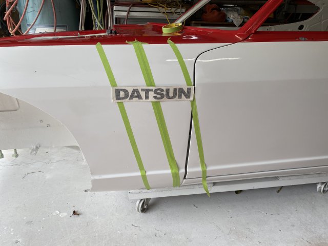 Racing Stripe with Datsun Logo
 After Striping and Clear Coating
 Rear View
.JPG.8cd1faa64bdf56b79a2f0a6048d79bcc.JPG) Side View
Side View
 Came out real smooth.
 Inside view
.JPG.0ee9651e2f6bfe6798d17dc4cbe6f6cb.JPG) Simple and but Effective.
Simple and but Effective.
 Outside view of Exhaust Filters.
 Only a Light Coat of Black Primer Spray is necessary,
.JPG.c0438528f8e74b1e17131a8ed93bf4e2.JPG) Hood with the Low Spots covered with a thin layer of Body Filler.
Hood with the Low Spots covered with a thin layer of Body Filler.
 creating a Body Line.
.JPG.c8afd2c598c547cdbc7a04a907c290f3.JPG)
 Cowl Panel masked to prevent overspray.
 Cowl Panel with Low Spots filled.
.JPG.18d77a5183ff8c8eb835f61a63f07abf.JPG) R/Quarter Panel and Door Sprayed.
R/Quarter Panel and Door Sprayed.
.JPG.eb21a694a75fbce16a7041e20d3cdcb7.JPG) Right Fender ready for more sanding.
Right Fender ready for more sanding.

.JPG.9e220f0d1e7a016801b8bdb6533cc8de.JPG)
.JPG.50bd00e594580c5c463936723d026d32.JPG)
 Unsuccessful for now!
.JPG.b2dd1331200136ebb7a99043fea9e7b6.JPG) Note: The Plate is folded on the outside edge of the the Plate. This Fold
Note: The Plate is folded on the outside edge of the the Plate. This Fold
.JPG.b770ca406132be444f306df6134468c0.JPG)
.JPG.27f6f5330ee80874b8f47a905e78fc9b.JPG)
.JPG.c575d6f26f5c279c9a1a3ab06163ebbc.JPG)
.JPG.0acdc5292cf1ce70becbb0ec5a40414d.JPG)
.JPG.119c45b5f66687a09a9103aa29695945.JPG)
.JPG.23aa6b7799d9bab6906d5b8df9a87e28.JPG) If necessary, you can sand the sealer smooth.
If necessary, you can sand the sealer smooth.
.JPG.3d8420afe1bfc111082271416ccfc4cf.JPG)
 .
.
.JPG.1f6d923d7b3c02b3351d984413b44ca2.JPG) Note-the original holes were only 3/16".
Note-the original holes were only 3/16".

 Center mount was mounted to the frame extending to center of Valance Panel.
 Left and Right Mounts before Powder Coating.
 Left Valance Mount powder Coated installed

 Inside view of Left Flare
 A 2000watt Infared heat lamp provided the heat.
 Powder Coating the Grille parts.
 The Grille was powder coated with Flat Black Powder then assembled.
 Note- I use almost all the fender edges( top, back, front and bottom) to create the
 Side view of template
 Transfer the trim lines using a Black Marker pen.

 Blasting away
 Stub axles after paining with Black Polyurethane paint. Note- the rubber joint
 Before Powder Coating
 After Powder coating
 A flange bolt powder coated
 Note- new Camber adjusting bolts were installed.
 Front to rear view of Front Suspension. Note -The Powder coated parts gives
 Side view of the Right Side Suspension


 Remember that this tire is only 18" so the 9 1/2 tire will stick more inward.
 This stick show the wheel offset. The "C" line indicates the center line of the Rota wheel.
 Front tire clearance shown
 Front to rear view

 In this case, a 274 x45 tire cross section was created and bolted to one of the wheel legs.
 You just rotate the simulated tire cross section to check any clearance issues with body and strut.
 Check Front Clearance of the flare.
 This method was used because although slow, it has less chance of damaging the


 id
id
 1/2 Dial Torque Wrench
 A Dial Inch Pound Torque Wrench checking Turning Torque( about 4 inlbs)


 Central cowl area sprayed
 right side of cowl
 Left Rear Wheel Housing interior area sprayed.
 Note-the 3/16" steel rod between the quarter panel and wheel housing can be seen.


 Front view of Right Wheel housing sprayed.
 Right rear Wheel housing sprayed.
.JPG.618c03ca6859a3c800412e6cc9d8014f.JPG)

 R200 differential was also painted.
 Rear Strut housing painted.
 The distance between the Top Center of the Wheel Opening to the one of

.JPG.bd6c0d05d8add7d96999edff187b8dc7.JPG)


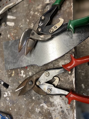 This patch was created using Left and Right Cut Tinsnips. They make cutting curves
 Front patch after hammering and metal shaping.
 Top Wheel Housing Filler patch
 Rear Wheel Housing Patch
 Rear Housing Filler patch

 After sealing the inner top section of the wheel housing, area was painted with polyurethane paint.
 Bottom view of wheel well housing after
 Overall view of rear flaring modifications
.JPG.f8f7ec4dfdc6e3639faeca609c5781ad.JPG)
 Always cut carefully to prevent "over cutting too much".
 A Hand Nibbler was used in the Finishing Cuts.

 The Outer edge of the flare is marked
 Bottom view of the wheel well(looking upward from the ground)
 Side view of additional cutout.
 Patch being mocked up.
 making gap fillers
 Overall view of the gap fillers


 Note- the bottom of this patch had to be
 Additional pounding with a Ball Peen Hammmer.
 The Patch fitted into place then tack welded in.
 Inside of the wheel housing, EverCoat Epoxy Seam Sealer was applied over all welds and all seams. Polyurethane paint will be spray painted over all of the repaired areas. The inside wheel well areas will also be covered with
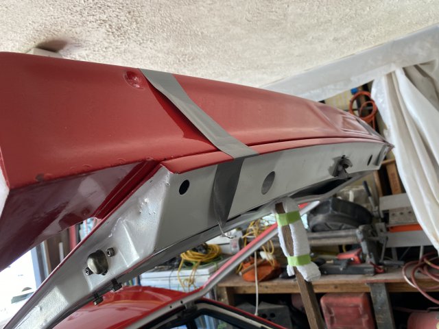
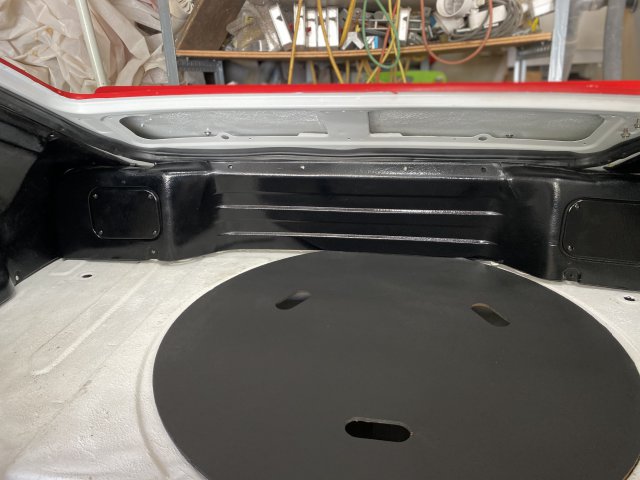
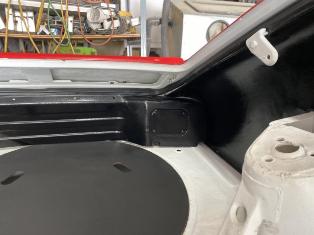
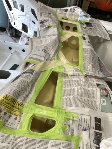
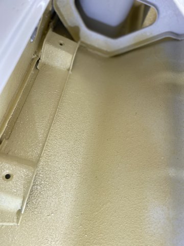
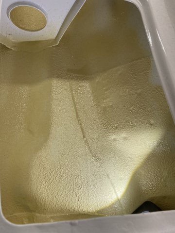
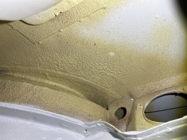
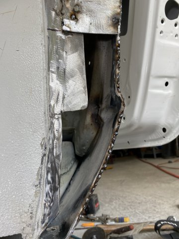
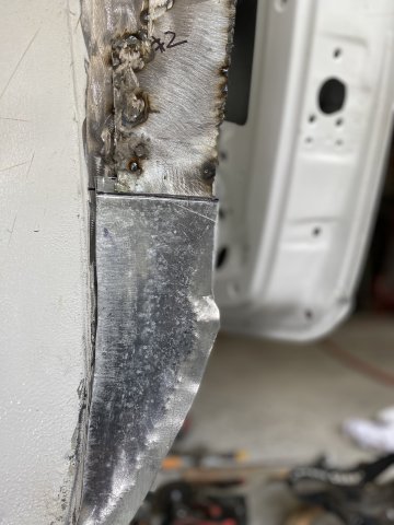
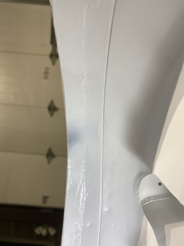
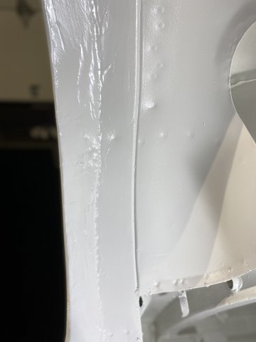
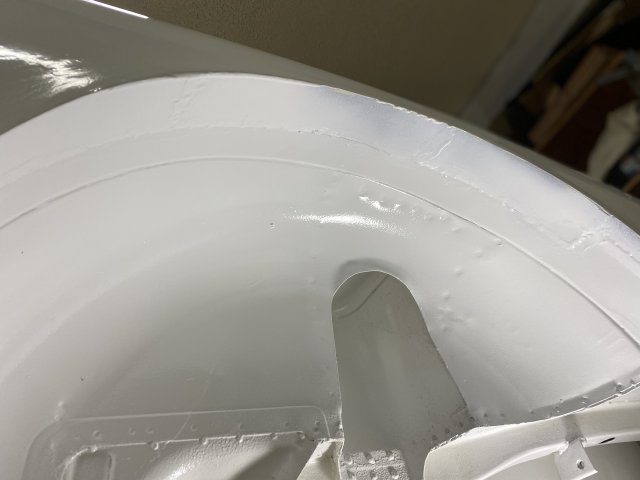
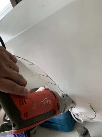
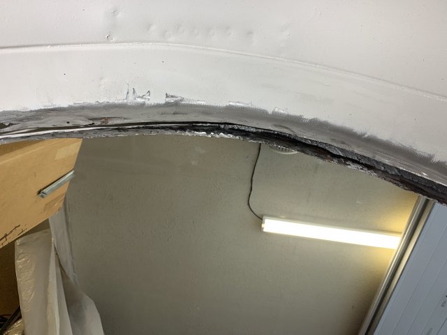
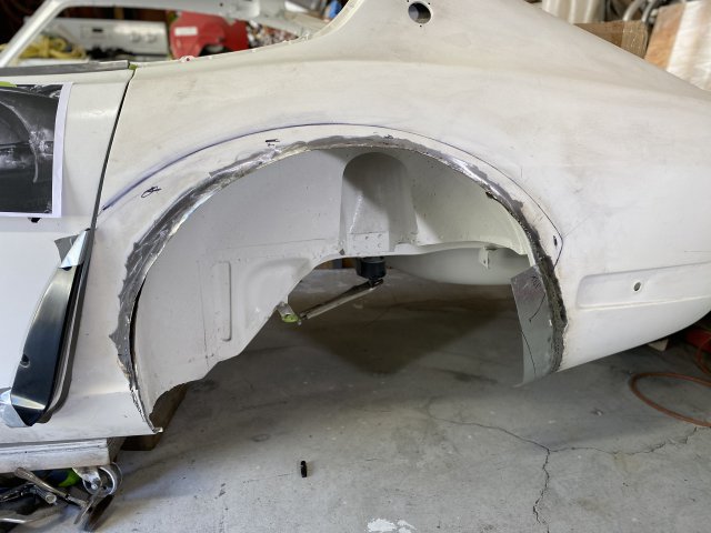
Hatch Hinge Pocket Rust Repair
in Body Kits & Paint
Posted · Edited by toolman
added text
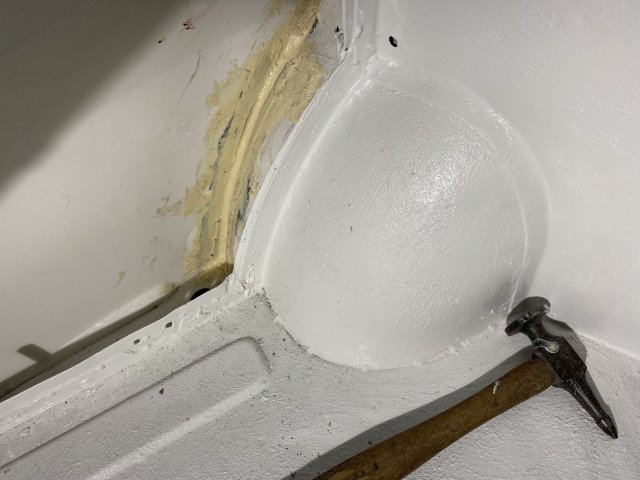
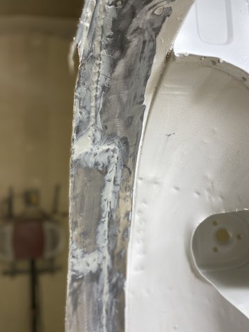
Robert, I think you are correct in assuming that a leaking hatch hinge liner was the main cause of the corrosion. I inserted my borescope into
that INTERIOR LIGHT channel that holds both Right & Left hinges. Only the hinge boot keeps water from entering the channel. If you didn"t have those big rust
holes there under the R/hinge, water would mostly flow along the channel then go down the inside of the rear quarter panels. Then the water
would exit from either the front or rear wheel well edges. To repair it. by cutting those rust holes out and cover the area with a sheet metal patch
welded on the botton side of the channel. Use polyurethane seam sealer to the top side of the patch. A new hinge boot will keep the water from
entering.