

toolman
-
Posts
523 -
Joined
-
Last visited
-
Days Won
8
Content Type
Profiles
Forums
Blogs
Events
Gallery
Downloads
Store
Posts posted by toolman
-
-
Exhaust Pipe Construction
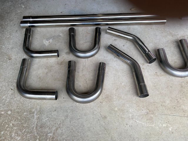
I started off with Super Fast Racing 2 1/4" Stainless Steel DIY Custom Exhaust Pipe Kit from Amazon. It was about $149. The kit consists of Two 45 degree, Two 45 degree, Two 90 degree bends and Two 48" straight
sections of T304 Stainless Pipe.

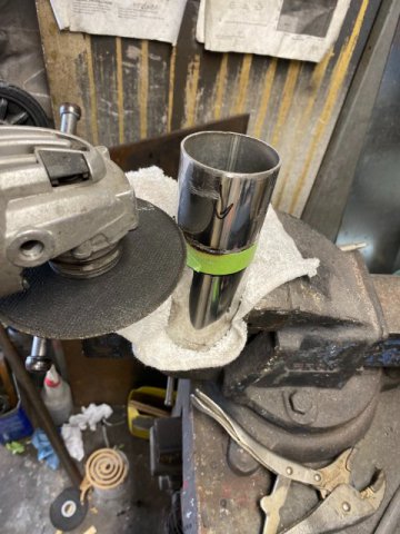
I used a Electric Band Saw that can cut up to 4 3/4" .but you can use a !4" Chop Saw, a Sawzalll or even a 4 1/2 Right Angle Grinder with !/32" cutting disc.
A Band Saw does make the job easier.
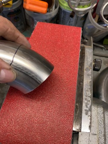
A Craftsman 2/3 HP Belt Sander was utilized to straighten cut pipe edges.
A 4' x 36" x 36 grit Ceramic Belt provided fast sanding.
A Astro Pneumatic Small Air Belt Sander with 80 girt belt was useful in sanding tight areas,
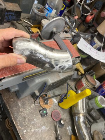
Since this project using a Tig Welder, there was going to be a Very Steep Learning Cruve involved. So I practiced, practiced and practiced. Welding Thin Wall Stainless was like being thrown in the Deep Side of the Pool while learning how to swim! But I managed to get a hang of it but my Tig Welds were not anything to brag about.
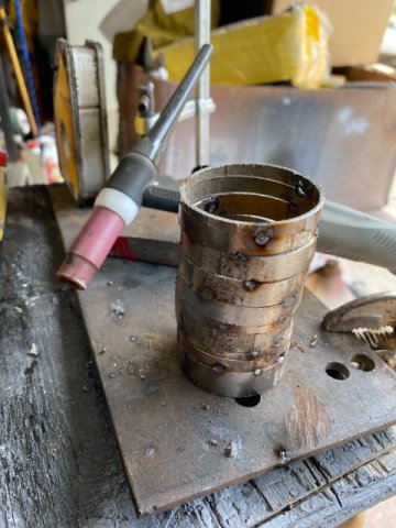
Practicing Butt Joint Welding
When Tig Welding, Clearness is vital. So you wipe down the area to be welded with Acetone to remove any contaminates ( from even brand new parts). Then, you should bevel both edges of your Butt Joints and sand the weld area. At the same time get the Butt Joints as Tight as Possible. Here is a Welding Tip: Instead of Purging with Argon Gas the inside of the pipe, use Solar Flux type B. It comes in a Pint can and cost about $49 on Amazon. It is a dry powder that you mix with Alcohol to create a mud like paste. You brush it on the inside of the pipe under the area to be welded. When it dries, the paste will prevent "sugaring" which is oxygen contamination of bottom side of the weld. Sugaring will create a tiny facture which can crack later especially something subject to constant vibration. Another benefit is Argon Purging is very Expensive so wasting it is foolish. Solar Flux, however, can not be used upside of a turbo because its residue might get suck in and damage the turbo blades.
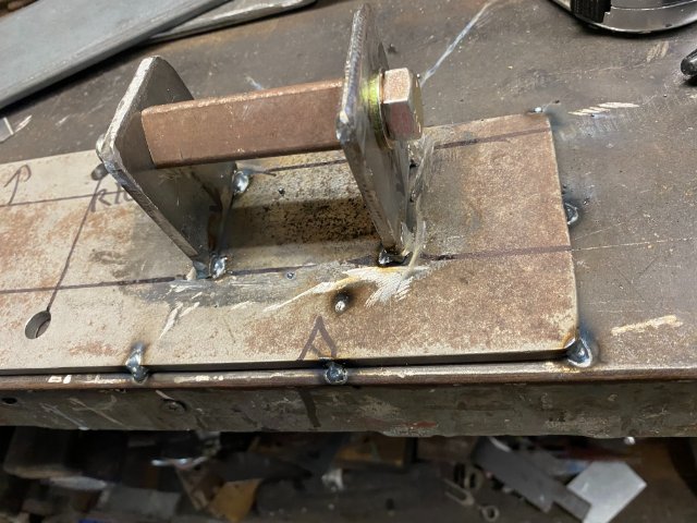
I also constructed a Tig Welding Jig to hold round exhaust pipe when welding. The round pipe can be easily rotated when tig welding the butt joints.
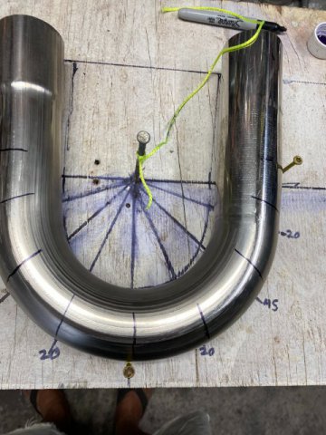
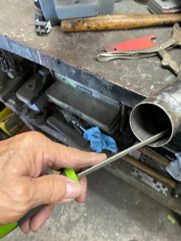
To cut the U-Bends, I created a cutting board to mark the pipe for cutting.
Using the string and a marker pen to mark off angles.
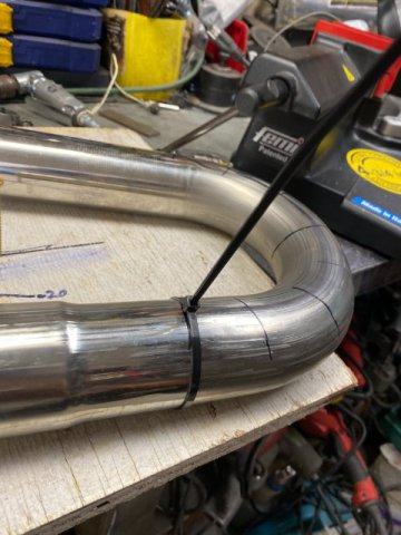
Zip Ties on the pipe helps making lines around the pipes.
After Cutting the U Bend, you will notice that pipe sections are not perfectly round( more "egg shape". This is because these so called Mandrel Bends are not True Mandrel Bends. Just Cheap Versions. However, True Mandrel Bends are available but cost a lot more.
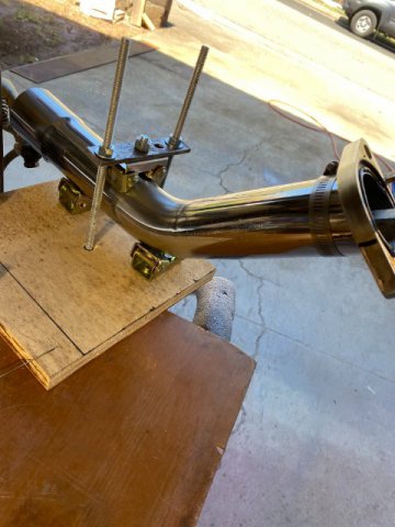
.Passenger side Front Pipe
Driver Side Front Pipe
Two Flex Pipe Sections were used to absorb engine vibration to exhaust pipes.
Using 3M Masking tape to hold sections whenf test fitting.
Creating "S"Bend pipe
Cutting with a 4 1/2 Right Angle Grinder. Use the Thinner 1/32" cutoff wheel makes cutting easier.
Removing the sharp edges after cutting eliminate potential stress points.
Making Pie Cuts
Next-More Exhaust Work
-
New Exhaust System-
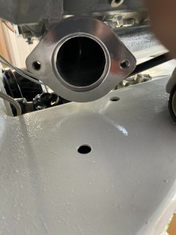
After installing the Holley Flow Tech LS exhaust manifolds on my car, I discovered there was a Clearance Problem.
The Driver Side -No Problems
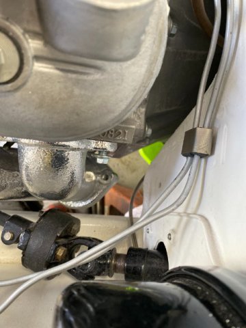
Steering Shaft
Firewall
Frame Rail
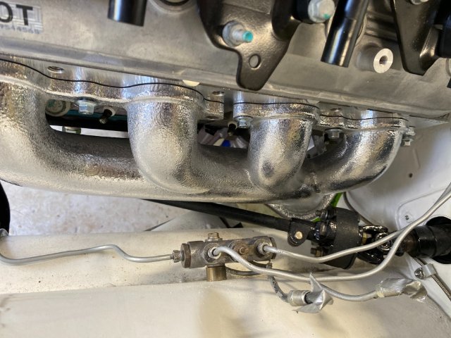
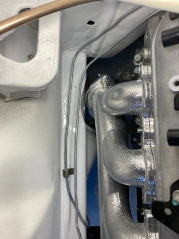
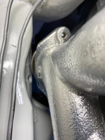
However, the Passenger side Exhaust Manifold was too close to the Frame Rail.
The Passenger Side was touching the Frame Rail so I tried to cut off about 3/8" off the bottom manifold ourside edge.
But ,it was still too close. I considered shifting the motor to the left but that side didn't have the extra space.
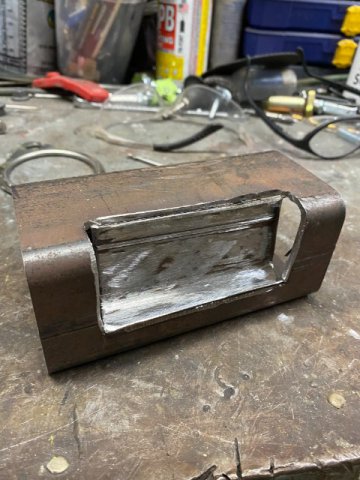
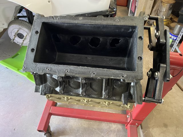
So the only alternative was to "Notch" the Frame Rail.
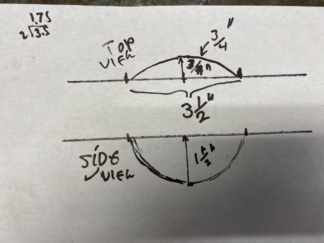
This is one the possible Notch design.
This model was made using the same Frame Rail material.
But no matter what, Notching would require the motor and transmission removal again! This would be the Sixth Time the Motor/Trans had to be removed. Nobody said engine swaps were Easy, right?
Out Again
This is the my Drawing of the Frame Notch modification.
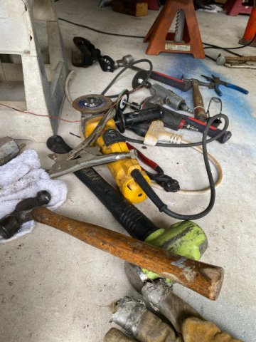
Here is a pic of the Tools necessary for this job.
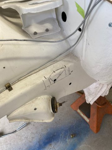
The Passenger Frame "Marked Out" in preparation of the modification.
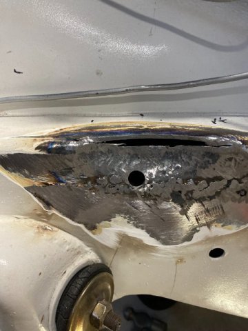
A 4 1/2 Right Angle Grinder with Cut Off Wheel was used to slice the Top Edge of the Frame Rail.
Then a Oxygen Acetylene Torch heated the Notch area "Cherry Red". Then a 5 pound Sledge Hammer pounded
the area. to create a "Rounded Spot"
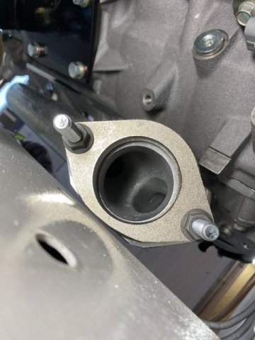
The Upper Frame Rail were cut to match the cruve of the Notch. Then 3/16" gap was then welded with a Mig Welder with Two Welding Passes.
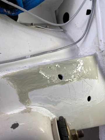
The Notch and Weld was grinded and covered with EverCoat Polyurethane Seam Sealer. The area was then painted with Polyurethane White Paint.
Note-those holes were previously
drilled there for future rustproofing access. The rust proofing plugs will then be installed,
Top View of Notch
Closeup View
The Brake Line was moved away from the Manifold at this
time. The Vapor Line was also moved.
Next- Exhaust Pipe Construction
-
DonH, Thanks for feedback on the Leather Seat Covers. Good to know that Company makes Good Covers.
Dash Board Installation-
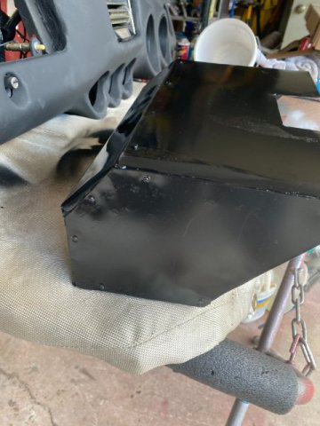
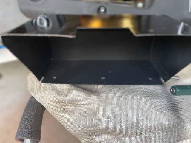
After receiving the SEM Textured Black Dash Board Paint, I repainted the Dash Board. But while installing the dashboard, I discovered that the my Aluminum Replacement Glove compartment had to be modified to fit. The Compartment Top had to be Notched to clear
Dash board Ducts Hoses.
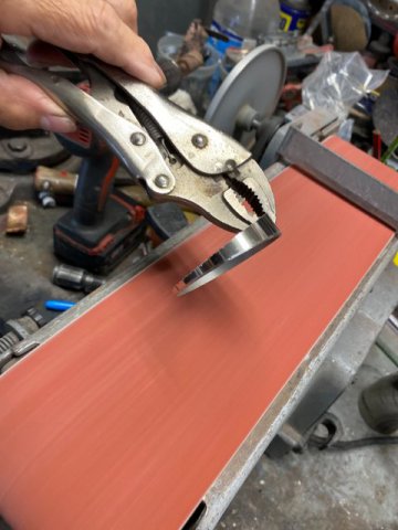
Used the Brake to create the Notch
for Glove Compartment.
Cleco Pins were used to test fit the Notch on the Glove Compartment Box.
The Notch installed on the Box.
Interior of Box was painted with SEM Textured Black Paint.
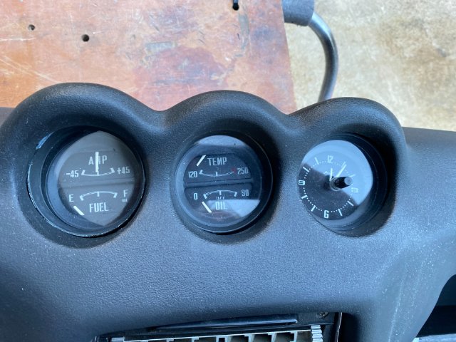
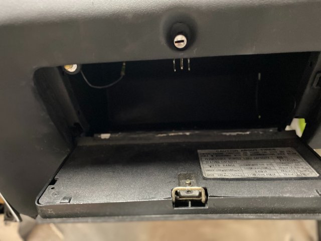
Pic of Finished Dash Board Installed.
Giove Compartment Box completed.
For those of you who missed the Dash Board Restoration- Go back to Feb 4, 2019. The Dash Board was in Eight Pieces after it fell off my work bench.
Exhaust System Build-
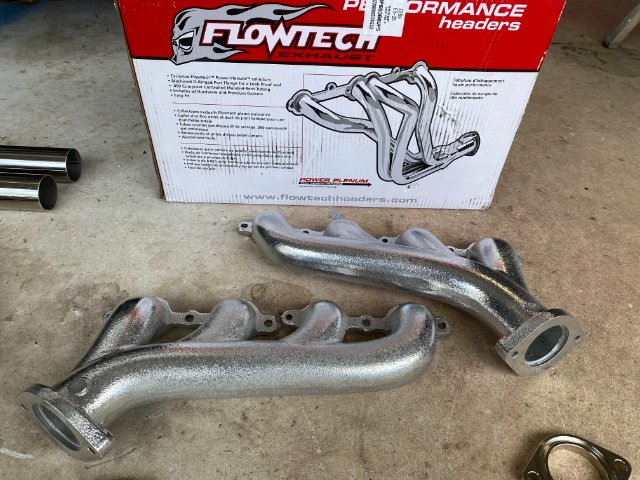
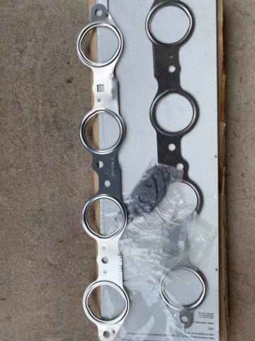
I decided to build my Exhaust System starting with Holley Flow Tech LS Cast Iron Exhaust Manifolds. They have 2 1/4" outlets and are Ceramic Coated. Cast manifolds will
eliminate some of the Heat and Sound in the engine compartment. Ebay sells them for about $260.
The Rest of the Exhaust System would be fabricated from this Universal 2 1/4" Stainless Steel DIY Kit from Ebay. It costs about $150.
LS Exhaust Manifold Gasket Kit runs about $20 on Amazon
Building an Exhaust System for a 240z without a Exhaust Tubing Bender and a Vehicle Hoist
will not be easy. Especially making it out of Stainless Steel Tubing and the fact that I never
Tig Welded before. Please be Patience with me!!
-
Sorry for the delay in posting but couple of unforeseen problems came up. I was planning to go over the installation of my Reconditioned Dash Board but could not find the SEM Products Textured Dash Board Spray Paint on the island. Since Federal Express and UPS won't ship Pressurized Containers, my Spray Paint would have to come by Boat. That trip would two to three weeks so I went to another item to restore.
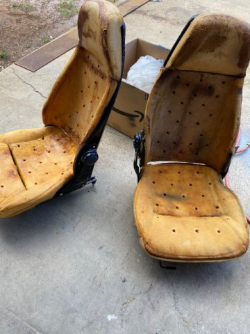
Front Bucket Seats Restore
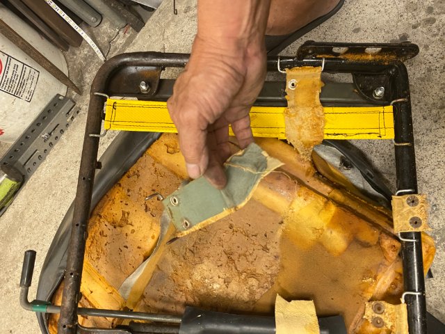
Both Left and Right Seats had lot of wear so probably would go Restoring them in Leather. First Step was to Disassembly to check the internal condition of the seats.
Removing the seat coats just requires removal of the Hog Rings that hold the covers on.
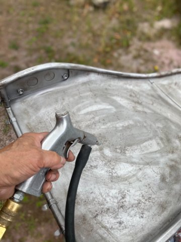
Sand Blasting Seat Frame and Back
They put a Thin Clear Plastic Sheeting over the Seat Foam to make it easier to "slip" the
new Seat Cover over the Foam. It can be replaced with any real Thin Plastic Sheeting(like
the kind from Dry Cleaning Shops).
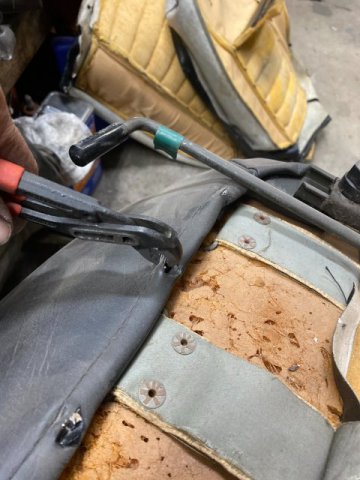
Both Seats had Broken Seat Support Straps( located under the foam seat cushion).
If you plan to repair the seats, you need to save the Metal Support Wires that hold the seat covers to the frame as they might not come with new seat covers.
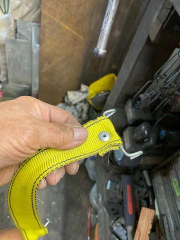
I used Webbed Belts from Ratcheting Cargo Straps to replace the Broken Straps.
Loop the Cargo Straps around the Old Factory Strap Connectors . Hot Glue is used between the Folds to provide
additional strength. A 1/4 Air Riveter is used to install the 1/4 rivet to secure the webbing tightly too. Solid Aluminum Rivets can be utilized.
Close Up View of Repaired Strap
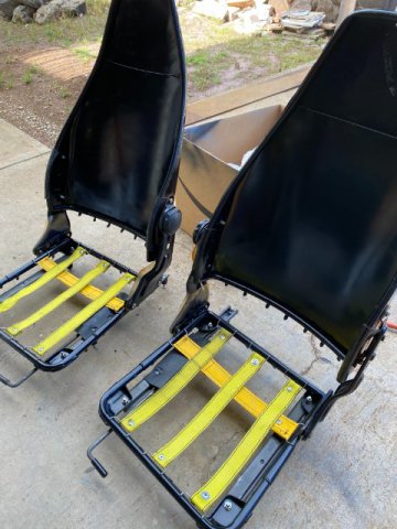
Both Seat Frames were sandblasted and painted with Black Urethane Paint.
Seat Cushion Straps installed.
Seat Cushions installed awaiting Seat Covers.
Pricing both Vinyl and Leather Seat Covers on Amazon and Ebay came out to $400+ for Vinyl and about $700
for Leather Seat Covers. I decided to wait and possibly look for Junk Yard or Craigslist for a Pair of fBucket Seats.
Next-Exhaust System
This should be interesting as It will be the First Time that I will Tig Weld and Weld Stainless Steel Exhaust. Wish me Luck!
-
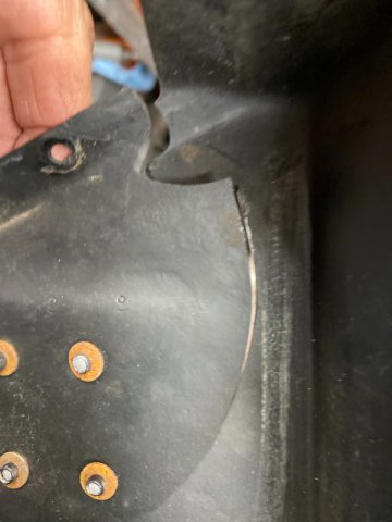
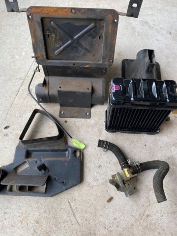
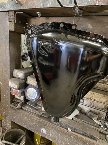
Heater Box and AC Evaporator Unit Repair
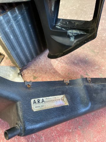
pic of A.R.A. Evaporator Unit apart
A company called A.R.A. provided their AC Conversion Kits for the local Nissan Dealers 240Zs which did not come with OEM AC until later models. The kits were bolt-in operation with Condenser, Evaporator Unit, York Compressor & Engine Mounting Bracket, Dryer, and Hoses. Installation time was about 4-5 hours. In those days, only R12 Freon was utilized .
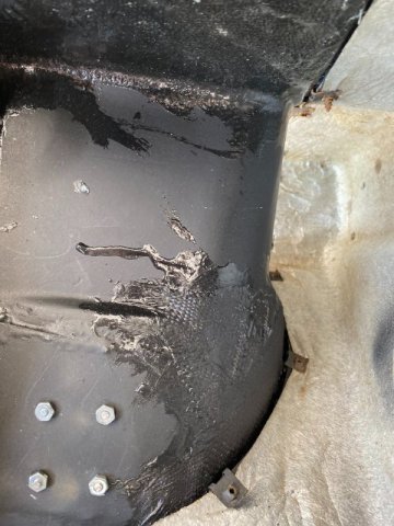
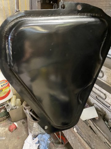
Major Crack found in Evaporator Case.
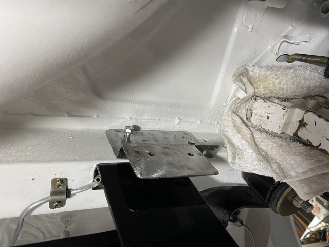
This interior area of the plastic Housing will also be repaired with Fiberglass and reinforced with a Steel Metal Plate on the exterior.
Reinforcement Plate
.
After Repair and Painting
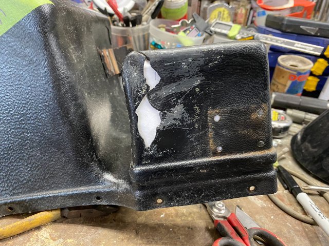
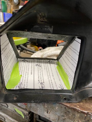
Found the Evaporator Outlet cracked
Making Paper Template for Reinforcement Section for Outlet
Paper Template
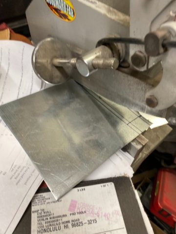
Cutting 16 gauge Metal for Reinforcement Section with Shears
Reinforcement Finished
r
Test fitting of Reinforcement Section in Housing
Reinforcement was later fiberglass laminated to the interior in housing. Exterior was also laminated to repair broken sections,
l
New Firewall Mount finished.
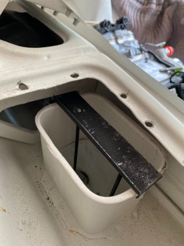
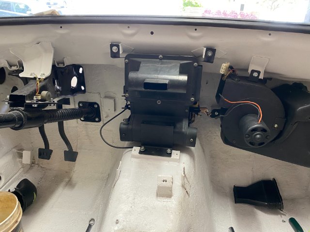
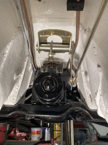
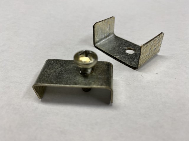
The Heater Box is normally attached to the Cowl Inlet Vent with Four Small Screws. I decided to mount the Heater Box by a different method.
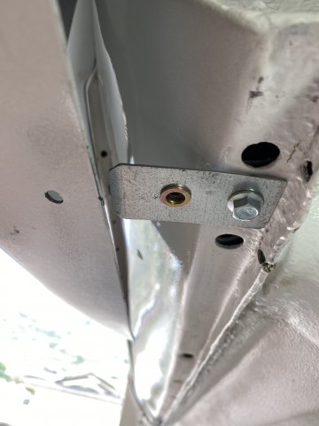
Instead of the screws, I made a Right Angle
Bracket that would support the Heater Box from the Top of the Cowl Cold Air Inlet. Two Threaded 10-32 Rods would be suspended from that bracket. The rods would go through another bracket
attached to the Heater Box Housing. Two nuts on the rods were be tigntened till they supported the Heater Box to the Cowl Inlet. This similar hanging mount was utilized on 64 to 70 Ford Mustangs Heater Boxes.
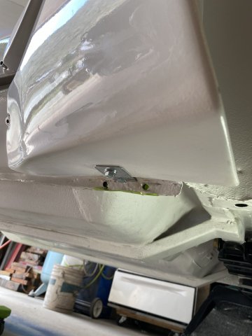
Top View of the Heater Box Mounts. Normally, the Cold Inlet Vent is covered by a Sheet Metal Cover.
Note- To tighten the two Mounting Rod Nuts, the Duct Door made be in "Open" Position to access the nuts.
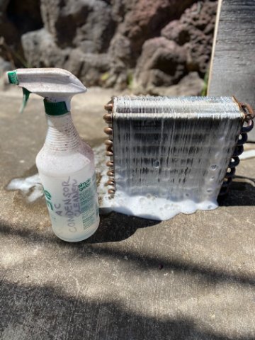
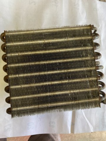
Both Heater and Evaporator Cores were cleaned with AC Condensor and Evaporator cleaner. Cleaning removes grim and mildew from the Aluminum Fins.
The Foaming Action cleans the cores.
All Cleaned.
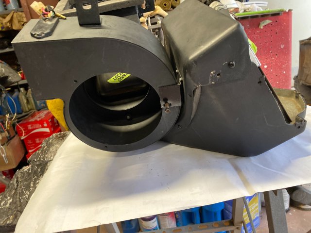
The Heat Box Completely Disassembled.
Heater Fan Unit and Evaporator Unit attached together.
Both Heater Box and AC Evaporator attached to Firewall and Cowl Vent.
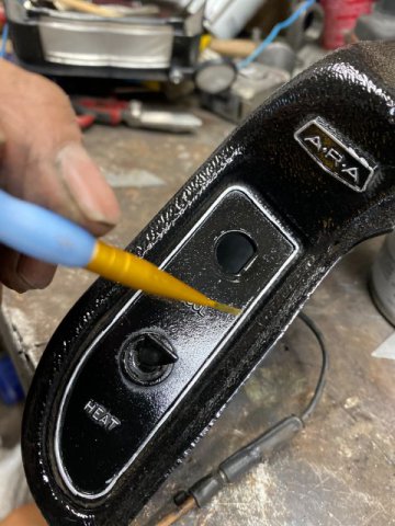
AC Control (mounted on left side of Console Panel
Was Touched up with a Brush and Chrome Silver Paint.
Finished off with Clear Spray
Next-Dashboard Installation
-
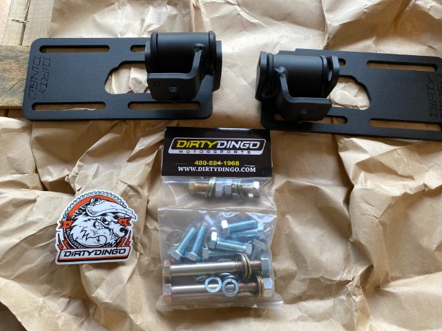
Twisted46, Go to my Post-Heavy Duty Frame Rails Feb 13.2021 to see what I did to modify the Diorty Dingo Mounts. I wanted to set back mm LS3 close to the Firewall too.
JTR Mounts puts the LS mounts more forward than Dirty Dingo too if you don't want to fabricate a new motor plate. Check the related photos to see if the clearance
is sufficient for your purpose. One disadvantage of the forward mount position is you can not locate an AC compressor on lower front side of the motor. You probably
will have to mount the compressor high on the Right motor side(near valve cover). The other option is reinforce the frame rail and locate the LS motor mounts directly
on the LS block mounts. That position would allow for the lower AC Compressor mounting but might interfere if you are running full length headers. Engine Swapping is
a "Give and Take" Proposition.
Tool Man
-
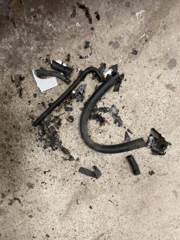
Fuel Venting Hoses-
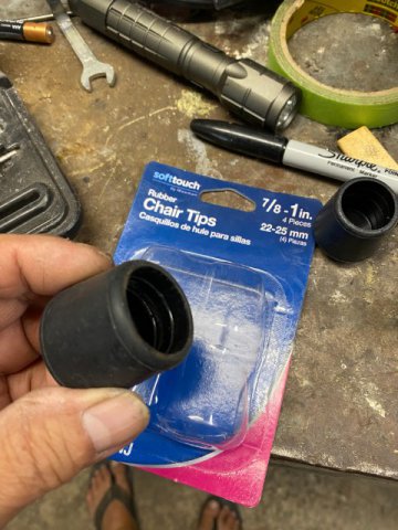
One of the problems of the 240z is the Gas Smell in the interior of the vehicle. Leaking Hatch Weather Stripping,Leaking Tail Light Housing Gaskets, and Leaking Fuel Vapor Hoses. There are Three Different Fuel Vapor Hoses used in the Fuel Tank area. The usual sizes (inside Diameter) are 5/16", 5/16" and 3/4" Neoprene Fuel Hose. Instead for searching for various sizes of Rubber Hose Sealing Grommets, I decided to fabricate my own.
These were four for $4.
The Local Hardware Store had 1" or 1 1/8" Wooden Chair Leg Tips.
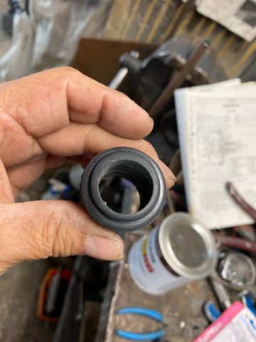
First, I drilled a 1/8" Pilot Hole in the Chair Tip and drilled it with a Blair 5/8" Hole Saw.
Then Drilled it with a Blair 5/8" Hole Saw.
Chair tip fitted on Hose
Test Fit
Note-Tight Sealing Tip
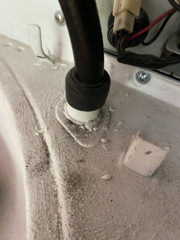
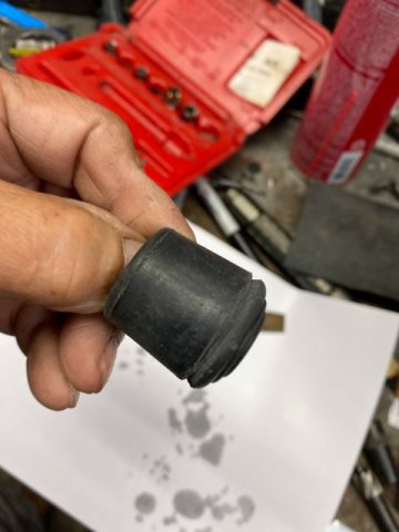
For the Fuel Vapor Hoses going through Sheet Metal Holes, the Tips Tapered Exterior Body
was utilized.
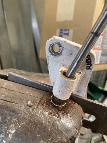
The Chair Tip was "Notched" at appropriate diameter with a File and Hack Saw Blade.
The Notch became a Locking Edge to hold
the Chair Tip in place.
Check Upper Left Corner to see the Locking Notch Chair Tip installed on a 5/16" Fuel Vapor Line.
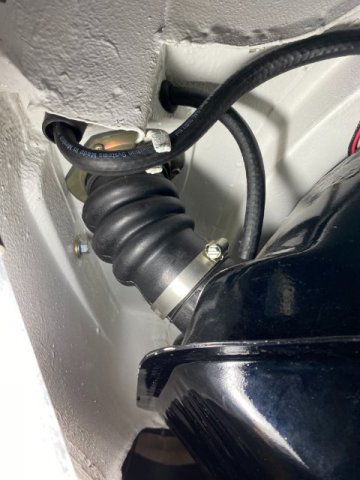
Bottom View of Fuel Output, Fuel Return and Fuel Tank Vent Hoses on tank.
Bottom View of Upper Fuel Tank 5/16" Vent Hose next to Fuel Filter.
Bottom View of Fuel Outlet and Fuel Return Hoses above Differential.
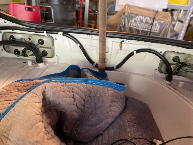
Rear Interior View of Fuel Vapor Hoses in Rear Tail light Panel.
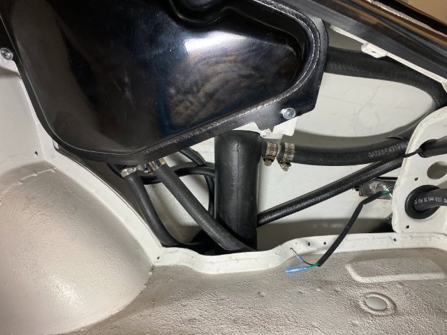
Passenger Side Interior View of Fuel Vapor Tank and Connecting Hoses
Next-Heater Box and AC Evaporator Repair
-
Z DEPOT did refund me for the brake parts that did not fit properly on my car. It took about a month of communicating by email as they don't want to
talk on the phone. Hopefully they will return to using the telephone as the Pandemic comes to a end.
Toolman
-
Transmission Cross Member-
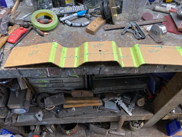
As always, the first thing to do is to create a card board template of the Transmission Cross Member.
Then, the Trial Fitting of the Template.
As you can see, there are plenty improvements to do the card board board template. The Transmission Crossmember will have to built with a much "tighter fit" to accommodate the big exhaust pipes (2 1/4" to 3") with sufficient ground clearance too.
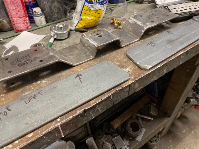
A 14" Chop Saw was used to cut the 1/4" steel plate. I bought 1/4" x4" x 20 foot steel plate for $67 to save time in
cutting the long lengths. That left me more time to work on just cutting 4" width cuts.
By cutting only half away through through the plate made it easier to bend since I did not a Heavy Metal Press Brake. If you cut it right, you can still bend it by hand but it will be strong enough to test fit it on the car.
.
The Klein Angle Finder was utilized to check the plate angles.
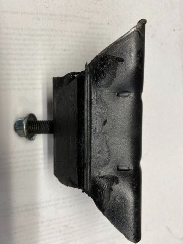
The Stock Transmission Mounts was trimmed to gain additional clearance.
Stock Mount Before
Mount After Trimming Four Corners
This trimming allowed the Plate to be closer to the Mount.
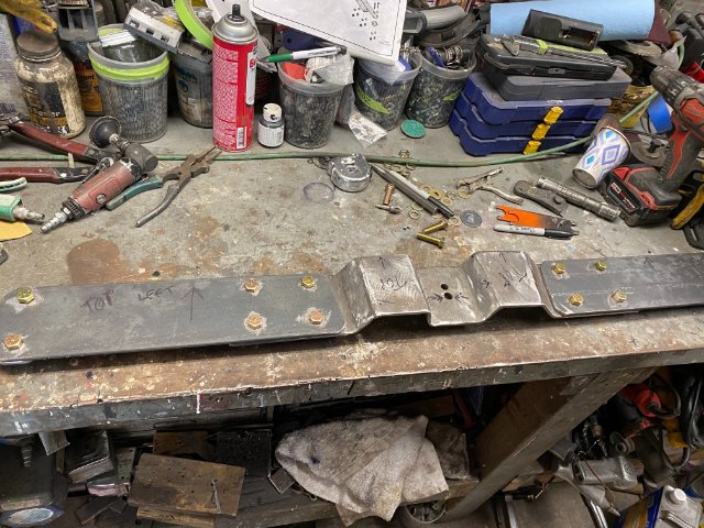
The Cross Member was first tack welded then test fitted then fully welded.
The Cross Member was tack welded to another 1/4" steel plate to prevent warping /
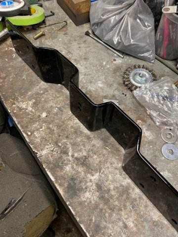
Note-There is a change in the shape of the Trans Crossmember. These changes created maximum space for the exhaust pipes.
Cross Member Powder Coated Black.
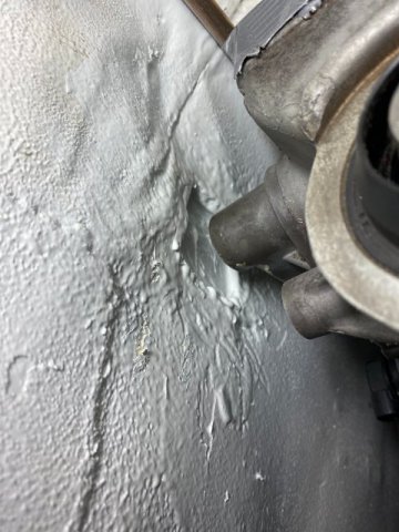
Because of the Extreme Motor/Trans setback, the Reverse Lock Out Solenoid was touching the trans tunnel. I could have eliminated the Solenoid or Modify the Trans Tunnel. I decided to do
the Later.
I fabricated a small Sheetmetal Hump to provide Solenoid clearance.
Interior View of Tunnel Modification
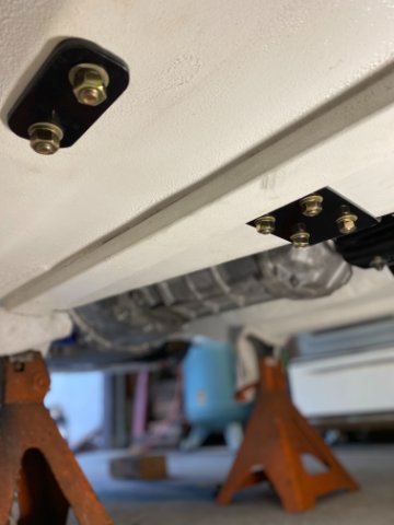
I also added Four 1/4" Steel Plates to reinforce by "sandwiching" the interior floor panel between
the Transmission Cross Member. Remember, that they are Two !"X 3" x !/8" Rectangular Steel Tubing Frame Connectors under the floor pan, too.
These are the Two 1/4" Reinforcing Floor Plates being fabricated.
Trial fitting of Reinforcing Plates and Crossmember bolted together.
Cross Member Powder Coated Black
Passenger Side Interior Reinforcing Plate
Bottom View of Cross Member
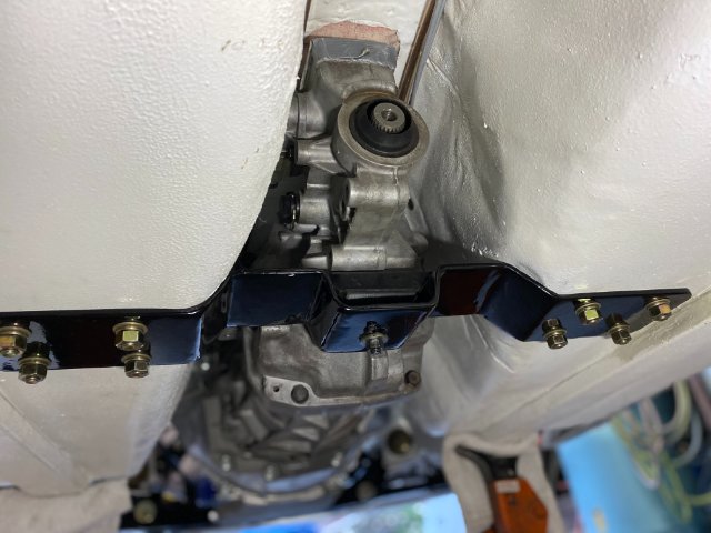
Back View-Note Tight Fit compared to First Version
Bottom view-Cross Member
Cross Member, Upper and Lower Reinforcing Plates held together with 3/8" Yellow Zinc Bolts
Outer Reinforcing Bottom Plate( one on each side-Left and Right
Interior Upper Reinforcing Plate( one on each side-Left and Right
Left Side Interior Upper Reinforcing Plate( Note-Frame Connector passes under this plate
Close Up View of Trans Mount
Next-Finalizing Fuel Tank Venting Hoses
-
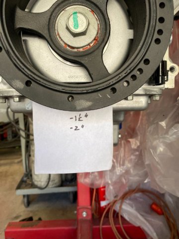
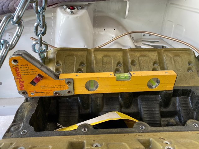
Drive Line Angles
Now that I have my Motor Mounts made and LS motor installed, the construction of the Transmission Cross Member could to be done. But first, the measurement of the Drive Line Angles is necessary. This because the Transmission Cross Member will determine the Motor and Transmission Drivetrain Angle #1. If the Crossmember was constructed before checking Drive Line Angles and I needed to adjust Angle #1, it might require making a new Crossmember to change the angle. So checking the Drive Line Angles now and establishing Cross Member height before makes sense.
Angle #1 is the Motor/Trans Angle
Angle#2 is the Drive Shaft Slope. The Last one is
Angle #3 -Pinion Shaft Angle. The measurements (if possible) should be with the Vehicle Level and at normal Ride Height.
How To Measure Drive Shaft Angles – Tom Wood's Custom Drive Shafts (4xshaft.com)
This article gives a good overall view of the measurement procedure.
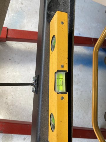
I downloaded the Tremic App from the App Store to my IPhone. I used the
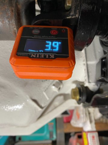
Klein Digital Angle Finder from Home Depot-$39.
It has a strong magnet and very easy to use. The digital readings are big and with the black background readable even outdoors.
All measurements were made in the Center Line of the Drive Train.
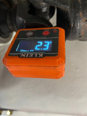
Angle# 1 Motor/Trans Angle measured at Front Driveshaft Yoke
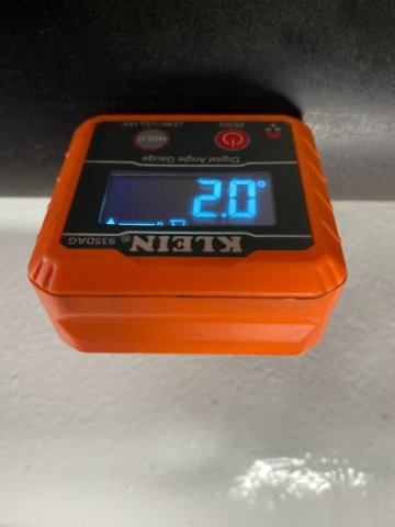
Angle# 2 Measured at Driveshaft Center-Driveshaft Angle
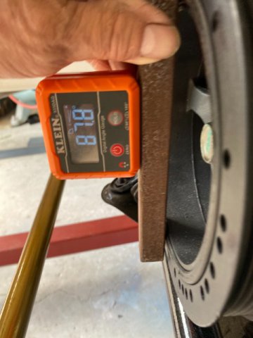
Angle# 3 Measured at Rear Driveshaft Yoke-Pinion Angle
I transferred these measurements in the Tremec App.
The Results-Everthing in the Green-PASS
If there was a measurement in Red, there would be a problem with that Angle or Angles and should be corrected. Shimming or other methods can be employed to adjust the angle.
For those without Iphone or Digital Angle Finder can get a similar results with a manual Protractors and a Straight Edge. The Formula is:
Motor/Trans Angle-2.3 Degrees
minus Drive Shaft Angle-2.0 Degrees
=0.3 Degrees
Pinion Angle-3.9 Degrees
minus Drive Shaft Angle-2.0 Degrees
= 1.9 Degrees
Using my measurements in this case
Next-Transmission Crossmember
-
After couple of days of emails, I am happy to say that ZCAR DEPOT finally realized that there was a fitment problem with their booster. They are working on a solution.
If they improve the customer service, I think everyone will be happy. ZCAR DEPOT will also get increased sales.
-
Has anybody have problems dealing with ZCAR DEPOT? Previously, I have purchased mostly small items and stuff. But recently had
a fitment problem with a brake master cylinder from them. I tried to call them at 844-8652473, you get a answering machine which is
full so you can not leave a message. The only alternative coarse of action is to email them at sales@zcardepot.com and hope they answer
you. Their products are better than others but to me, their customer service is really terrible. If you had problems with them, please
comment here so others will know too. Maybe they will improve their customer service.
-
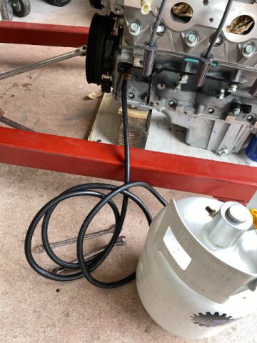
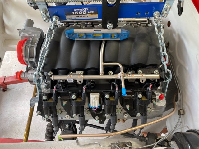
Prelubing the LS3 Motor-
I borrowed a Oil Pressurized Tank to prelube my LS3 motor as LS motors can not be easily prelubed like the older 350
motors. The operation is simple-Motor Oil is pressurized in the tank to about 50PSI and fed though the oil gallery plug. On the LS motor, it is located on the Front Left Lower Side. After starting to pressurizing the oil gallery, I rotated the motor
about 1/4 turn to allow the oil enter all of the passages. Keep rotating the motora 1/4 turn while checking the amount of oil in the tank to prevent creating air pockets in the oil passages. Continue until the oil reaches the rocker arms and springs or the recommended oil amount( 5 1/2 quarts in this case).
Motor rotated with a 1/2 breaker bar.
Clutch Slave to Clutch Fingers Clearance-
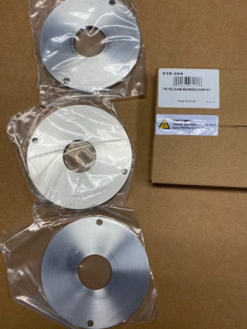
The Holley T56 Shim Kit ($39 from Amazon) arrived. The kit consists of 3 Thickness of Aluminum Round Shims
0.059, 0.125 and 0.185. The shims are installed to obtain the recommended clearance of 0.125" to o.200" between the measurements between the Throw Bearing(fully compressed) and transmission case face subtracted from the measurement between Clutch Fingers and Bell Housing Face. See pic below.
Holley Shim Kit
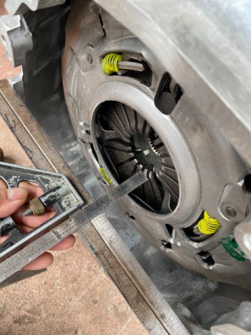
Bell Housing to Clutch Fingers Measurement
Using Straightedge and Machinist Ruler
s
Clutch Slave(with Spring Removed) to Transmission Case edge Measurement
Do not forget to remove Clutch Slave Spring while measuring.
In my case, only the 0.185 Shim was required to obtain the Proper Clearance.
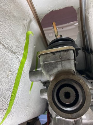
Clutch Master Cylinder-
I used Wilwood 3/4" Clutch Master Cylinder( $49 on Amazon). Also, used Russel 45 degree Banjo Fitting with Copper Sealing Washers for it.
Bench Bleed the Wilwood Clutch Master before Installation.
Wilwood Clutch Master installed with 36" Braided Stainless Steel 3AN Hose
Testing the Clutch Master and Slave before installing Motor and Trans into the Car
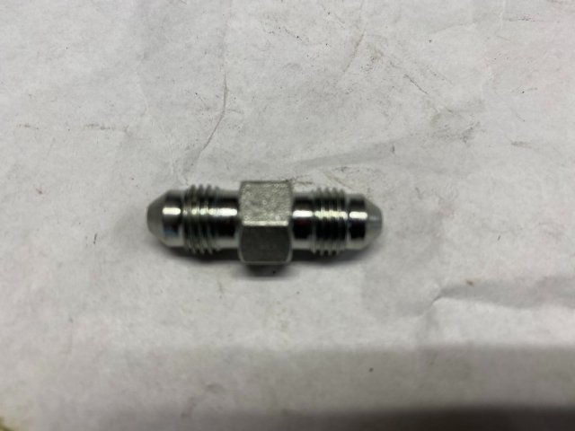
Most people probably would bother to test the Clutch System before putting it into the car but I rather be ":Safe" than "Sorry" and having to remove the motor and trans for a leak. I picked up a 3AN Union fitting to extend the clutch line to about 6 feet to do the system testing.
Before the Clutch Testing, Clutch Pedal Endplay and Pedal Stop adjustments were done.
To physically test clutch operation, Put the transmission in gear. The output shaft should not able to turned by hand. Now, pushing in the clutch pedal should release the output shaft and allow it to be turned by hand. This test verifies that the clutch is functioning properly.
Also, a Visual Inspection was done utilizing my Borescope.
No leaks at Bleeder Screw or Clutch Line Inlet.
Video of Throw Out Bearing operation
-
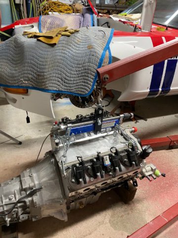
This is Toolman, I just removed my T56 transmission from a crate LS3 motor last week from under the 240z on jack stands. Jag that Run has their motors mounts. very forward on the LS motors like my mounts( check out my recent posts). I put a floor jack under the rear of the LS oil pan to prevent the motor from smashing the brake lines on the firewall. This engine setback lets very little room for trans removal though. I used long 3/8 extensions
with 12mm or 14 mm swivel sockets to loosen trans bolts. I removed the LS intake manifold because the plastic PCV valve was real close to the firewall. Also. there is only ten 8mm bolts holding the intake manifold. Installing the T56 transmission from under the car will be tricky. I borrowed a old floor transmission jack and will use two aligning studs to make the job easier too. Since the transmission is out, I am going to test the hydraulic clutch by adding additional 36" of 3AN line to test everything is working under pressure before reinstalling motor and trans into the car. I will use the borescope to see if the clutch is working OK. Some people will think it is a waste of time but I rather not take the chance of the clutch slave leaking.
-
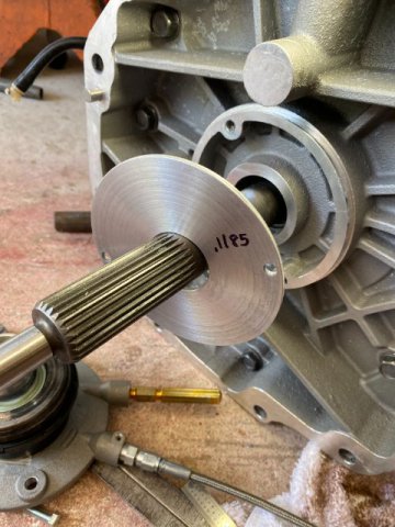
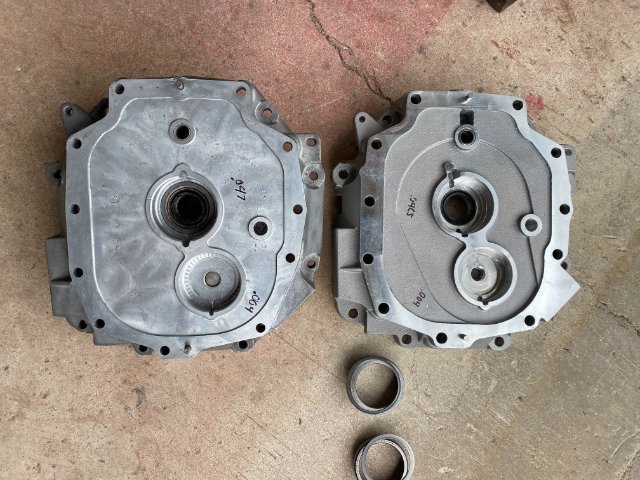
Sorry about the delay in posting but I ran across an unforeseen problem: my used T56 transmission that I picked up about 15 years ago would not bolt up to my crate LS3. After a lot of research, I found out to correct this problem there were basically Two Methods to convert my LT1 T56 to a LS1 T56 transmission. First and cheapest was shipping the Front Midsection Plate to a Mainland Machine Shop to machine it to accept a LS1 input shaft. The cost would be about $100 plus shipping( To and Back). Also, beside that I would still need a LS input shaft( used about$120) and LS Bell Housing( used about$150) The Machine Shops are in Washington State and Texas. I didn't want to ship the Front Cover to them and have something happen. So the other option was to purchase a new or used Front Cover Plate, LS1 Input Shaft, and a LS Bell Housing. So I purchased a new LS1 Input Shaft and LS1 Front Cover from AMP Distributing in Texas( for $210 and $240). Shipping was $60 First Class Mail. The GM Bell Housing was about $280 from Amazon. Total= $510 including freight. Fortunately, I only paid $1000 for a low mileage Iroc Camaro T56 trans back then.
Engine Side View of LTI T56 LS1 T56
Difference mainly around Input Shaft Area and Casting Holes for LS Hydraulic Slave and Bleeder
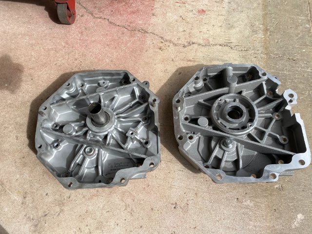
Difference between LT1 LS1 Transmission Side View
Relatively No Difference
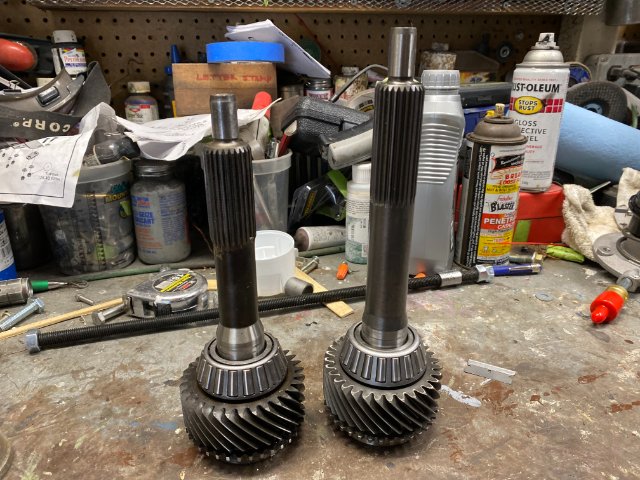
Input Shafts Differences LT1 LS1 much longer
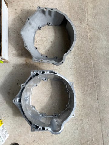
Bell Housing Differences
LT1- Top LS1- Bottom required Bigger Flywheel
Input Shaft Replacement-
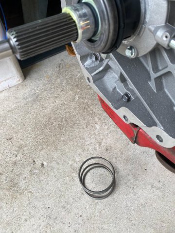
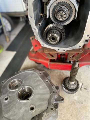
First, Remove Front Cover while pushing the Input Shaft inward to prevent Blocker Ring from falling out(can use a small screwdriver to hold it in position).
LT1 Input Shaft Removed by rotating it and "wiggling" shaft. At the same tie, Keep pressure on Input Shaft to prevent Blocker Ring from falling out. Take your Time.
Remove bolt Input and Counter Shaft Bearing by placing Eight Fingers on the inside of the races pulling outward while Rotating the Bearing Race at the same time. The Races should come out easily. Once out, remove shim under races and measure their thickness. Input and Countershaft have different diameters shims. I used a Felt Pen and write their thickness next to their bores.
I ordered a Tremec T56 Shim Kit ($50 from Ebay).
Then, after cleaning I replaced the Input Shaft Race with the New One and original shim.
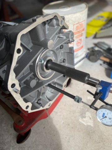
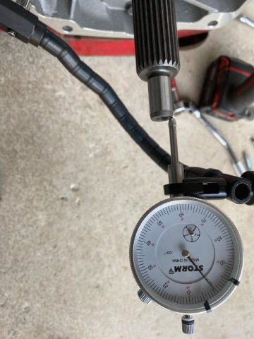
Then. put Counter Shaft Race with original shim inside. Setup Dial Indicator to check end play of both Input and counter shafts.
I followed the Tremec factory manual to obtain Endplay and PreLoad for Input and Counter Shaft. Even made their Special Tool(consisted of a Metric Threded Steel Rod) to insert in Counter Shaft. But I found the readings were too erratic. So I searched the Internet to find another method. A Transmission Rebuilder came up with this method.
This method was basicially over shimming the bearing under till the shaft "Binded" then remove .002 shim. Retorque it and test it again. The Test consists "Feeling by Hand" . DO NOT LAUGH!! I have seen racers adjust Rear Differentials by Hand and come out with Perfect Tooth Pattern. Note- The Tremec Shim Kit has 8 various thickness shims so you
have to "play" (add and subtract ) shims to obtain .002 removed shim.
Dial Indicators don't lie- .002 Endplay and Preload
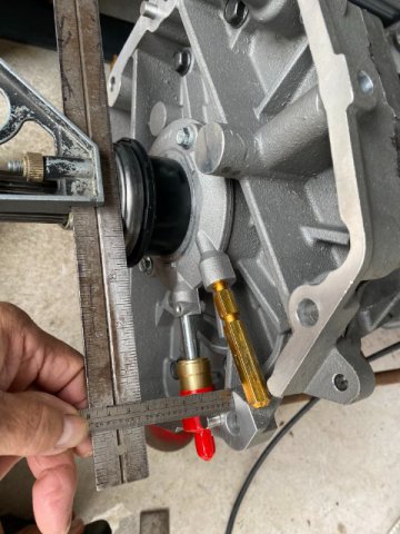
If you need to check Pressure Plate to Clutch Throwout Bearing Clearance-
Using Straight Edges-One across the Bearing, measure distance to transmission face.
Place Straight Edge against Bell Housing Face and measure the distance to Clutch Fingers. To get
Clutch Fingers to Throw Bearing Clearance, just subtract the Two Measurements for Clearance.
Engine Stopper-
I fabricated my Engine Stopper out of 1/8'" steel to hold motor from turning when tightening flywheel and pressure plate bolts.
Installed on Block
Next-PreLubing the LS3 motor
-
I used 1/4" Steel Plate.
Toolman
-
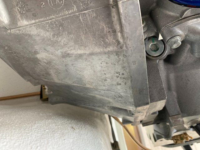
Bottom View of Bell Housing Clearance
Left Side
Top view
Removed Hood Lock Mount to gain more
clearance.
Right Side
Room for Exhaust not bad
Front View-Motor Mounts
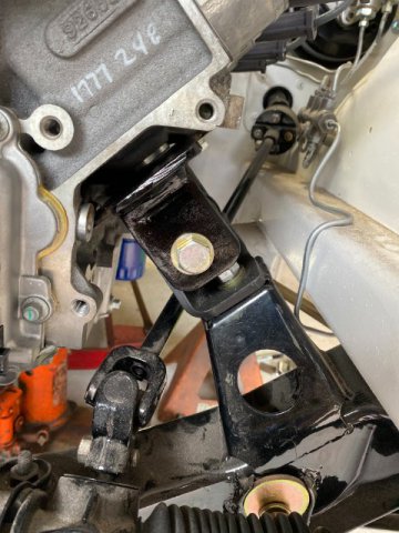
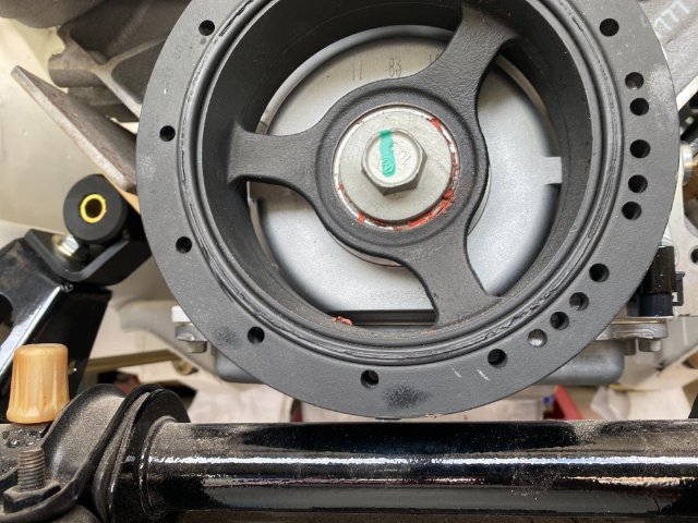
1/2" Clearance between Balancer and Steering Rack
Bottom View-Right Side Tight Clearance between Firewall and Motors
Tight Firewall to Motor Clearance
Front view of Both Motor Mounts
Next-Transmission Crossmember
-
Motor Mounts-
Originally I planned to used Dirty Dingo Z LS conversion motor mounts. But after installing on my Dummy LS Block in my car, I decided I wanted more engine setback than they could provide.
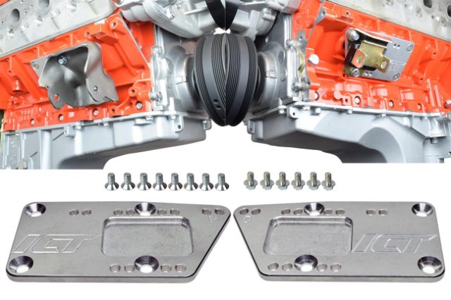
Also. looked ICT BILLET Mounts
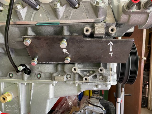
So I decided to basically make my own mounts of 1/4" Steel Plate.
As you can see, my version is 4" to 5" longer. I knew this was longer than necessary but usually go longer, just in case,, i need extra area to construct AC mounts too. I can always cut them shorter later.
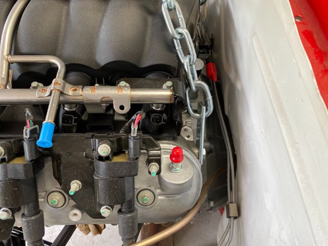
On the left bottom side of LS, there are two plugs.
The front one is a oil gallery plug. I plan to use this one to lubricating the motor before firing it up. The other plug is a freeze plug. The left mount was modified to give clearance of the oil gallery plug.
I took the oi pan measurements from my LS motor on the engine stand and place them on the Dummy Motor to check clearance between oil pan and rack. It had.
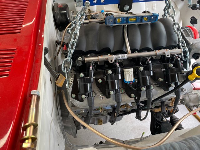
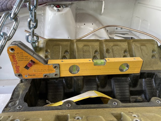
Checking engine level (length and sideways)
Checking body level (length wise and side side ways)
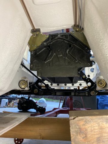
Checking engine rear clearance
The Steering Shaft was also checked for clearance.
Motor to Firewall Clearance checked
Note-Use of Wooden Blocks to temporary suspend engine while constructing mounts.
Tack welding the Mount Motors
Note- A Square Tubing Spacer was created to limit welding distortion. Also, the mount was tack welded to table for the same reason.
Between this final version of the Motor Mount and the first version, there were probably Three others (some only 1/ 4" difference in height). Trial and error had to be done to achieve the necessary results. Also,
while designing the mounts, one has to consider for other things(like air condition condition, power steering, alternator,etc).
Motor Mounts- Powdercoated
Note-access holes drilled for oil gallery and
freeze plugs.
side view
Left Side View
Top View
-
Witchboard, If your door adjustment is not the problem, you can try this procedure. The 240Z window door glass frames are rather flimsy. So you might need to bend
the top door edge more inward. You accomplish this by: Open the door and stick a 2 x 4 between the lower edge of the door and rocker panel. Now just push the top edge
of frame inward. By moving the window frame inward, it will decrease the window gap and hopefully stop the water leakage. Push easily at first and harder if necessary.
Also, check the driver's door for sagging. The upper door hinge pin wears and creates play.
Toolman
-
Rear Rocket Bunny Flares Moduicications
The Front Lower section of the Rear Quarter Panel Flares was not sufficiently secured down
So. I installed one 6MM x 1.0 nutsert to the underside of the rocker panel.
Then, made a 16 gauge sheet meta; plate to go over the nutsert. To give this plate additiona; strength, another plate on the exterior of the flare.
A hole was drilled through both plates. So you ended up with the flare sandwiched between both plates. Also, a right angle was added the inside edge of the plate so it was against the rocker panel pinch weld.
Side view of Quarter Panel Reinforcing Plates.
Late Christmas Present
Santa Claus delivered my Christmas Present at the end of December: 2020 Chevrolt LS3 #19370416 6.2 Liter 430HP/ 425 Lbs Ft torque. It
came from Scoggin Dickey Chevrolet in Texas. Cost was about $7600 plus $900 freight( truck and ocean freight). The shipment took about 3 weeks
from Texas to Honolulu.
My local Machine Shop offered me the use of his Dummy LS Motor to make mounts and check fitment issues.
Side View
Bottom View
Because its light weight, it was very easy to put the motor in and out of the Z to check fitment issues.
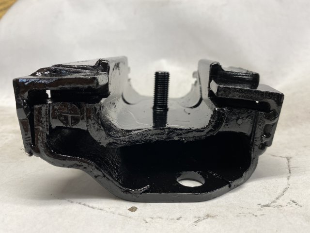
Differential Mount Modifications
With the additional torque from the LS motor, the original Differential Mount was modified. Some people use solid Differential Mounts but didn't
want excessive vibration and noise. However, the factory Differential mount has a low profile and is small in size. My solution was the cut off the corners
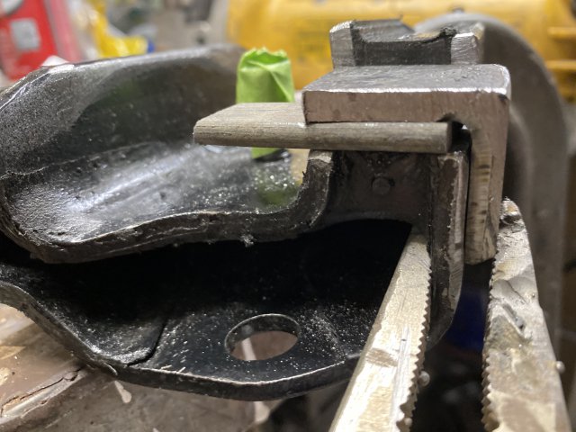
of the original mount then add Four 1/4 Right Angle Tabs.
The Right Angle Tabs being welded to original mount with
a piece of 1/4 "steel providing the "Air Gap". This design allows the Differential mount to operation normally until Load is applied then it will be "solid" mount.
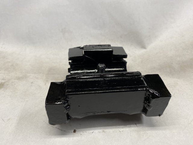
Finished Differential Mount.
Bottom View
Rear View
Side View
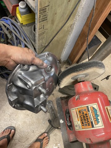
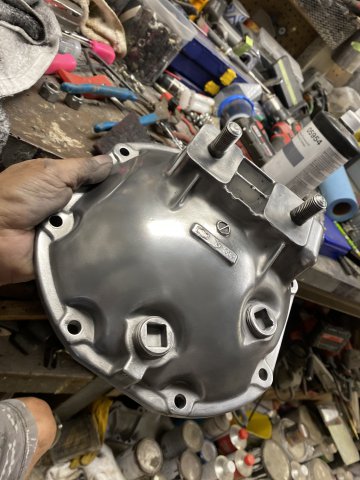
Rear Differential
The Differential Cover was Glass Beaded then hand sanded with 400 grit sandpaper. Then the cover was polished wih Aluminum Buffing Rouge
on the Buffing Wheel.
The Cover was painted with Polyurethane Clear. The Clear will prevent the cover from dulling out. The Carrier was painted with black Polyurethane.
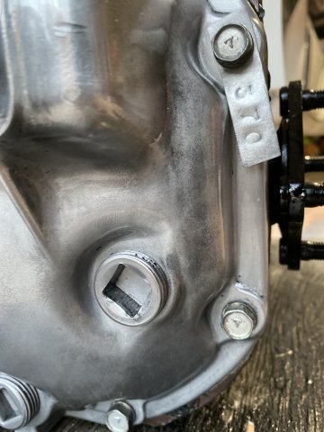
I had forgotten that this R200 differential contained 3:70 gears.
This gear ratio is much better suited than the usual 3.34 gears in most 240zs. Especially since, my T56 has a 2:55 First Gear. The combination should provide Wicked Acceleration.
LS3 Motor awaiting installation.
-
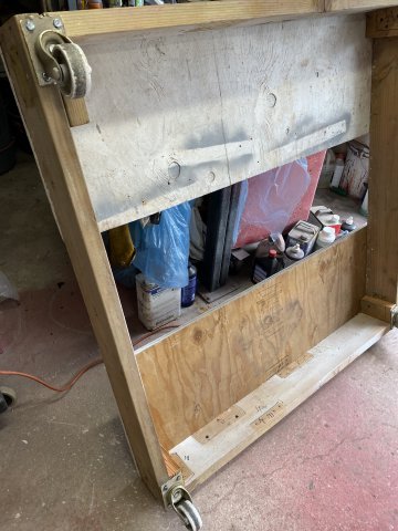
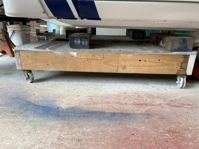
NEW CAR DOLLY-
I constructed a new car dolly to move the body around for engine and transmission installation. I used a lot of materials from "old car dolly". This dolly was about one foot higher off the floor to make working under car easier.
Bottom view of Dolly
Side view
After it was completed, I removed the jack stands and slid the Dolly in.
WIRING HARNESS-
The original wiring was in bad shape. The tape was starting to unwind and was covered with Rustprooting from in the quarter panels.
What a mess!
The wiring harness was hung from ceiling to straighten it out while I wait for the new harness wrapping tape from Ebay.
Fuel Evaporation Hoses
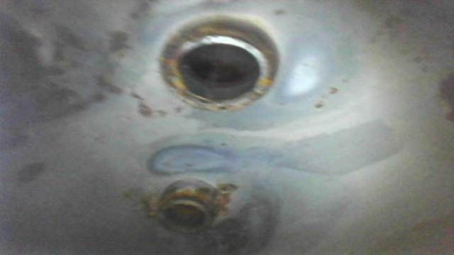
First, the Vapor Tank was cleaned and sandblasted.
Using the Borescope, I checked inside the Vapor Tank. It surprising clean.
Then PowderCoated.
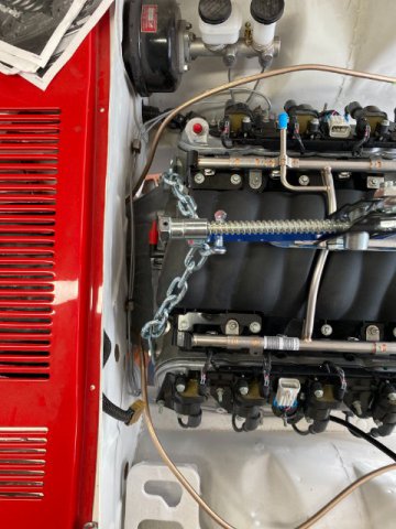
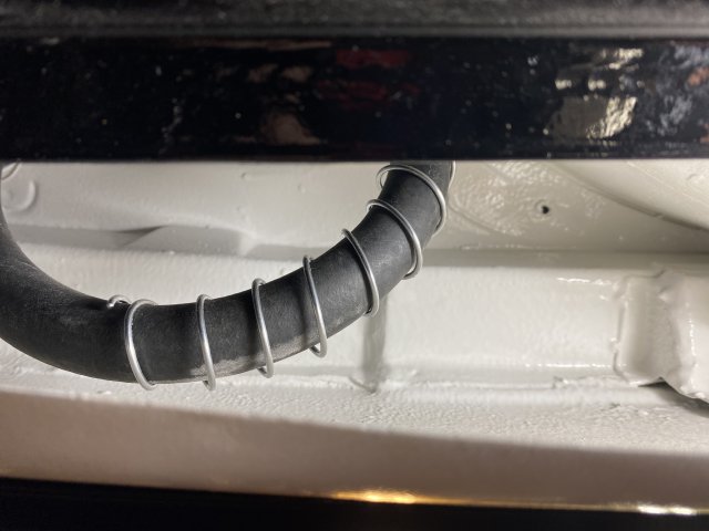
The !/2" and 3/4" vapor hose had springs added to the hoses from pinching. These were regular springs for now as the proper hose protectors were unavailable until January.
Vapor Hose diagram
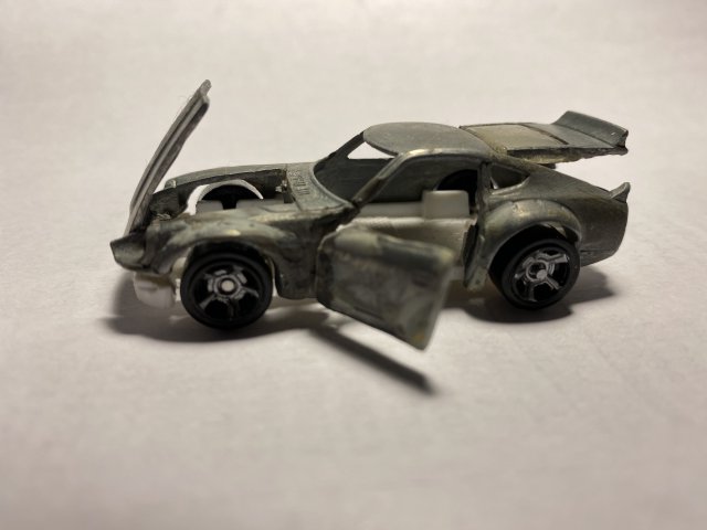
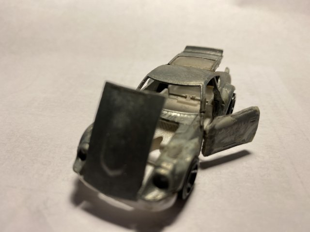
Hot Wheels 240Z modifications
I started this project about May 2020. Using the Hot Wheel Fugu 240z, I wanted to make it have opening door, hood and hatch. When I was a kid, I made model cars then modify them with opening doors and trunk. Then, made tube frame and working suspension. Even, advanced to lettering the race cars by hand.
I am keeping my eyes for a Hot Wheels LS motor and transmission, racing seats, roll bar and exhaust system.
Then, paint this car when I am not working on my Big Z.
-
Sorry for my delay in posting, I was busy putting up Christmas decorations for my house.
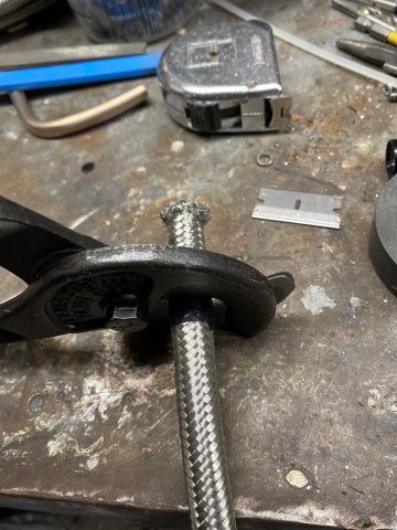
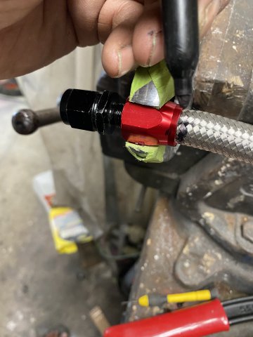
AN Fitting Installation-
Wrap Electrical Tape 3 or 4 times tightly around Braided Line. The Tape prevents the wire from unraveling.
Cut across the tape with a 24" Cable Cutter or use a Cutoff Tool.
Cutter will crush the hose like this but just squeeze it till round again.
Tip-Wrap a Plastic Cable Tie slightly down from the cut. I find it holds the braided wire tightly together ,otherwise the wire tends to spread outward when pushing into the socket.
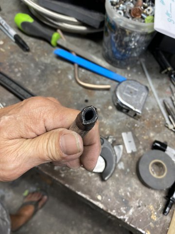
I wrap the socket fitting with a wrap of masking tape to prevent scratching.
Put Socket Side in a Vise to hold it tight then push the Braided Wire Counterclock wise while pushing inward into the socket. When the leading edge of the Braided Wire fully enters the socket, cut the Cable Tie off. Continue push the Braided Wire in
until the inner Black Rubber Hose( check by looking inside the opposite end) just barely touches. Once that happens, use a Felt Marker and put a line on the Braided Hose and edge of the Socket.
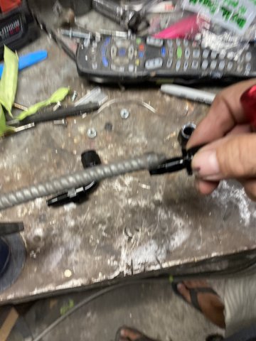
Lubricate the Threaded Section of fitting with Light Machine Oil or WD40.
Screw the Threaded Section in by Hand Clockwise until it gets tight then use a wrench to
tighten it down. Remember to watch the Felt Line that you made. If the Line moves away from the fitting is means that the screw is pushing the fitting outward and not screwing into the rubber section. If it is, you have to disassemble it and cut it off and start over.
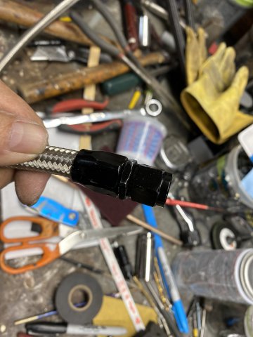
Finished product. Of course, the Real Test is to check under pressure.
This procedure was utilizing 6AN fitting which is 3/8" Fuel Line size.
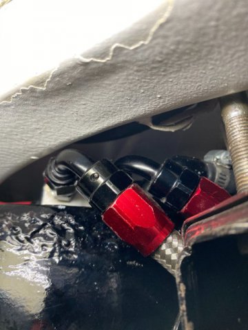
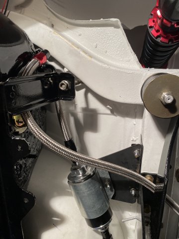
Braided Fuel Line Installation
From the Fuel Pump to the In Line Fuel Filter then to the 3/8" 4Life Nickel Copper Fuel Line heading the Engine Compartment.
The other( the closest) Braided Line is the Return Fuel Line to the Pump.
Both 3/8" Fuel Pressure and Return Line in the transmission tunnel.
Pic of Fuel Line Clamps.
Made from sheet metal then powdercoated Gold. Used Nutserts to attach the clamps to the tunnel.
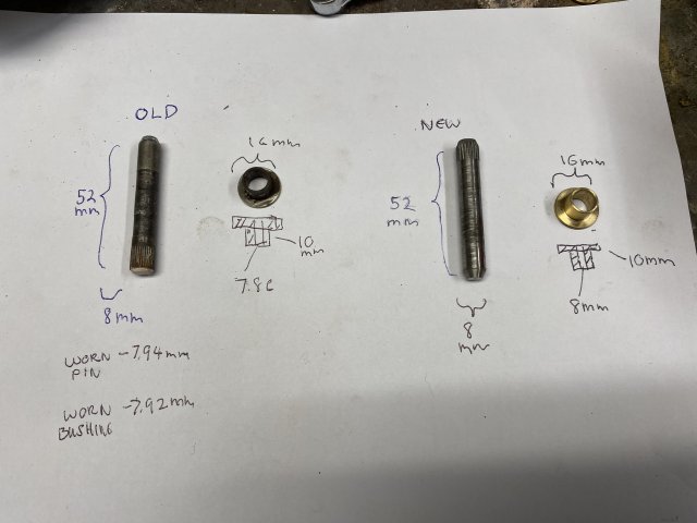
Replacing the Door Hinge Pin-
This replacement two Door Hinge Pin
came from Malta and cost about $50. It normally takes about 4 months to ship but the first shipment was lost in the Mail. So I finally
got my set in about 6 months. The pic shows the measurements of the replacement pin and brass inserts. A machinist should be able to
make in no time. Usually only the Upper Door Pin wears out as the weight is mostly carried on this pin.
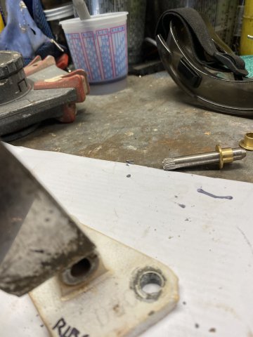
pic of assembled hinge pin
The Pin Bushing is removed tapping the pin out with a punch and hammer.
I used Anti-Seize on the pin to prevent further problems.
-
Robert, I think you are correct in assuming that a leaking hatch hinge liner was the main cause of the corrosion. I inserted my borescope into
that INTERIOR LIGHT channel that holds both Right & Left hinges. Only the hinge boot keeps water from entering the channel. If you didn"t have those big rust
holes there under the R/hinge, water would mostly flow along the channel then go down the inside of the rear quarter panels. Then the water
would exit from either the front or rear wheel well edges. To repair it. by cutting those rust holes out and cover the area with a sheet metal patch
welded on the botton side of the channel. Use polyurethane seam sealer to the top side of the patch. A new hinge boot will keep the water from
entering.
-
Yes, I am trying to keep some things original as possible.
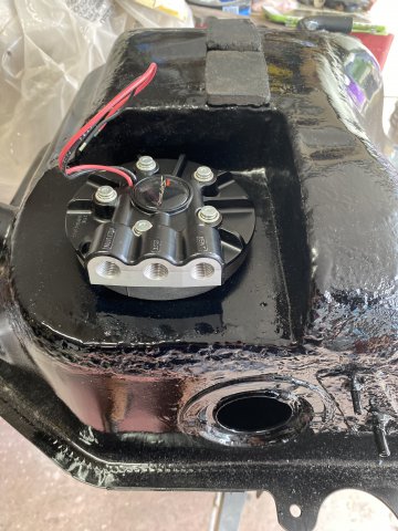
Back to Fuel Pump Modifications:
After measure the tank depth and setting the pump length. the pump was installed.
This pump can be rotated any direction that you prefer without drilling new mounting holes.
Left to Right- Return Line, Fuel Feed Line and Vent Line.
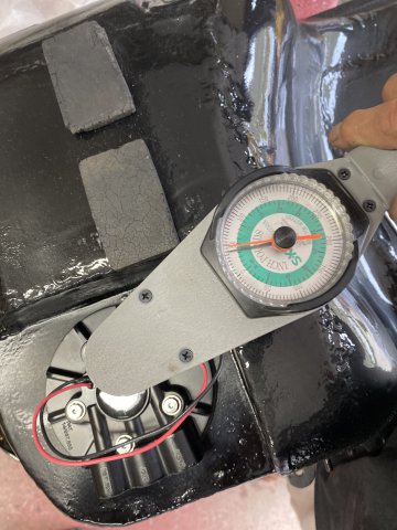
The pump mounting bolts were torqued to 50 in lbs in a Star Pattern and three increments.
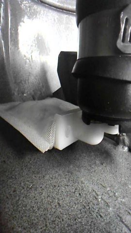
Using the Borescope, you can see the filter on the bottom of the tank inside the surge tank.
View of upper side of Fuel Pump
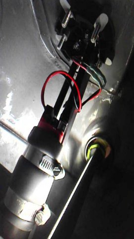
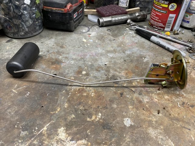
Because of the Fuel Pump location, the new Fuel Sender Unit had to be modified to clear the walls of the Surge Tank.
Using a Vise Grip, the Float Arm was bent to clear the Surge Tank Walls. The Float Arm can be adjusted further after putting Fuel in the Tank and comparing Fuel Gauge reading,
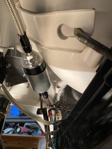
A 100 micro Inline Fuel Filter was installed between the Pump and EFI fuel Inlet.
This Filter
This Filter uses a Stainless Mesh Filter so it is reusable.
A Two Piece Bracket is constructed to hold the Fuel Filter.
It was made of 1/8" plate Steel.
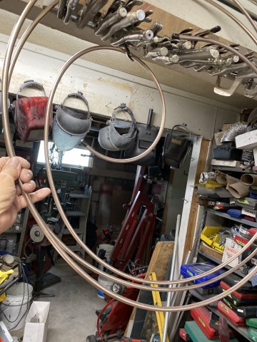
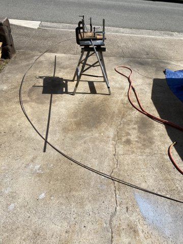
4Life Nickel Copper Fuel Line 3/8" x 25 feet purchased from Amazon. Came by Federal Express in a small 18" x 18" x1" box in
one big coil.
Start by slowly unwinding the coil slowly keeping the roll as straight up and down as
possible. When the roll is about 6 feet high, it is time to go outside. Use you feet to hold the lower part of the roll as you are unwinding and sliding your feet on the line.
Keep going till the line is relatively straight. Cut the line in half to about 12 1/2 feet long to make it easier to handle. A straight piece of 1/2" electric conduit(about 7-8feet)
was fastened to a portable work bench using two Vise Grips. The conduit should be small as possible for the best result.
Sliding the tubing back and forth rotating the tubing at the same time. Eventually the tubing should come out relatively straight.
Next Step to Make AN Fittings and Braided Steel Hose for the Fuel Lines.
Happy Turkey Day to All!!!
The bracket will be powercoated when completed.
 A Band Saw does make the job easier.
 A 4' x 36" x 36 grit Ceramic Belt provided fast sanding.

 Practicing Butt Joint Welding

 Using the string and a marker pen to mark off angles.
 Zip Ties on the pipe helps making lines around the pipes.


 Steering Shaft
 Firewall
 Frame Rail

 This model was made using the same Frame Rail material.
 Out Again

 Note-those holes were previously
 Top View of Notch
 The Brake Line was moved away from the Manifold at this
 Used the Brake to create the Notch

 Removing the seat coats just requires removal of the Hog Rings that hold the covers on.
 Sand Blasting Seat Frame and Back


 Close Up View of Repaired Strap
 pic of A.R.A. Evaporator Unit apart
 Reinforcement Plate
 After Repair and Painting
 Paper Template

 Reinforcement was later fiberglass laminated to the interior in housing. Exterior was also laminated to repair broken sections,
 New Firewall Mount finished.
 Instead of the screws, I made a Right Angle
 The Foaming Action cleans the cores.
 All Cleaned.
 Was Touched up with a Brush and Chrome Silver Paint.
 Finished off with Clear Spray
 These were four for $4.
.JPG.21353c50369d13b8e19073522dc8eebd.JPG)
 Chair tip fitted on Hose
 Test Fit
 Note-Tight Sealing Tip
 The Notch became a Locking Edge to hold
 Check Upper Left Corner to see the Locking Notch Chair Tip installed on a 5/16" Fuel Vapor Line.


 .
.

 Stock Mount Before
 Mount After Trimming Four Corners


.JPG.791c7a7bb55a3f59012cb6248146c762.JPG)
 Back View-Note Tight Fit compared to First Version


 The Results-Everthing in the Green-PASS
 Motor rotated with a 1/2 breaker bar.

 Holley Shim Kit
 Using Straightedge and Machinist Ruler

 Do not forget to remove Clutch Slave Spring while measuring.


.JPG.f0aa623eefd488437d945e3ba445cd8d.JPG)

 Bell Housing Differences
 LT1 Input Shaft Removed by rotating it and "wiggling" shaft. At the same tie, Keep pressure on Input Shaft to prevent Blocker Ring from falling out. Take your Time.
.JPG.d09961360d7c43a3113f3c9657855b5d.JPG)
 Dial Indicators don't lie- .002 Endplay and Preload


.JPG.e2a2c0ee8e5f8670b2d44ef0dfadfb38.JPG) Installed on Block
Installed on Block
 Removed Hood Lock Mount to gain more
.JPG.ed8369ba3ba3e54adec498be2abf945b.JPG)
 Room for Exhaust not bad


 Checking engine rear clearance

.JPG.1219073be6d670827c377a73327c0537.JPG) Note-access holes drilled for oil gallery and
Note-access holes drilled for oil gallery and

.JPG.a9fad476c2b0e9cef56c91499ddd5eff.JPG)

 So. I installed one 6MM x 1.0 nutsert to the underside of the rocker panel.
 Side view of Quarter Panel Reinforcing Plates.
 Bottom View
 The Right Angle Tabs being welded to original mount with
 Bottom View
 Rear View
 Side View
 The Cover was painted with Polyurethane Clear. The Clear will prevent the cover from dulling out. The Carrier was painted with black Polyurethane.
 LS3 Motor awaiting installation.
.JPG.d546283d287162c2b7233cdc7ca0f030.JPG)
 Bottom view of Dolly
 Side view
 What a mess!
 Using the Borescope, I checked inside the Vapor Tank. It surprising clean.
 Then PowderCoated.
.JPG.0a21b640294fee1adb5c2e2887f7ef8a.JPG)
 Vapor Hose diagram
 Cut across the tape with a 24" Cable Cutter or use a Cutoff Tool.
 Cutter will crush the hose like this but just squeeze it till round again.
 Tip-Wrap a Plastic Cable Tie slightly down from the cut. I find it holds the braided wire tightly together ,otherwise the wire tends to spread outward when pushing into the socket.
 I wrap the socket fitting with a wrap of masking tape to prevent scratching.
 Put Socket Side in a Vise to hold it tight then push the Braided Wire Counterclock wise while pushing inward into the socket. When the leading edge of the Braided Wire fully enters the socket, cut the Cable Tie off. Continue push the Braided Wire in
 Lubricate the Threaded Section of fitting with Light Machine Oil or WD40.
 Screw the Threaded Section in by Hand Clockwise until it gets tight then use a wrench to
 Finished product. Of course, the Real Test is to check under pressure.
 From the Fuel Pump to the In Line Fuel Filter then to the 3/8" 4Life Nickel Copper Fuel Line heading the Engine Compartment.
 The other( the closest) Braided Line is the Return Fuel Line to the Pump.
 Both 3/8" Fuel Pressure and Return Line in the transmission tunnel.
 This replacement two Door Hinge Pin
 pic of assembled hinge pin
 The Pin Bushing is removed tapping the pin out with a punch and hammer.
 I used Anti-Seize on the pin to prevent further problems.
.JPG.a56d1f6d6f6e913c2f489971abf3e5a0.JPG)
 Left to Right- Return Line, Fuel Feed Line and Vent Line.
 View of upper side of Fuel Pump
 Using a Vise Grip, the Float Arm was bent to clear the Surge Tank Walls. The Float Arm can be adjusted further after putting Fuel in the Tank and comparing Fuel Gauge reading,
.JPG.fd2b715591dc548c75cad148024f5fd1.JPG) This Filter
This Filter
 It was made of 1/8" plate Steel.
 Start by slowly unwinding the coil slowly keeping the roll as straight up and down as


Heavy Duty frame rails and connectors
in Gen III & IV Chevy V8Z Tech Board
Posted · Edited by toolman
duplicate post
.