toolman
-
Posts
614 -
Joined
-
Last visited
-
Days Won
24
Content Type
Profiles
Forums
Blogs
Events
Gallery
Downloads
Store
Everything posted by toolman
-
Heavy Duty frame rails and connectors
toolman replied to toolman's topic in Gen III & IV Chevy V8Z Tech Board
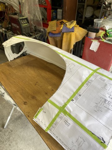
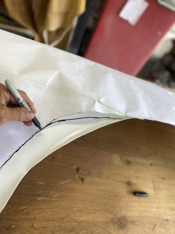
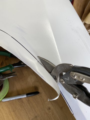
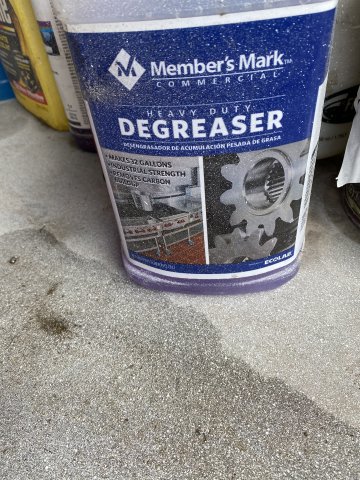
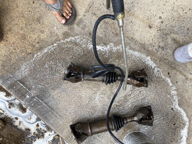
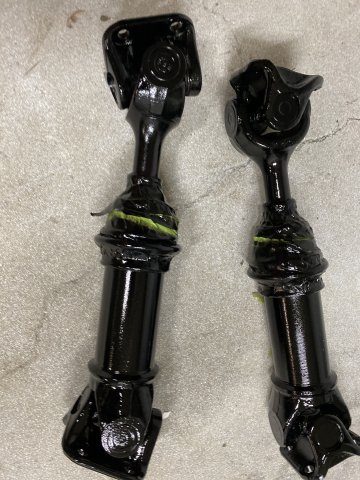
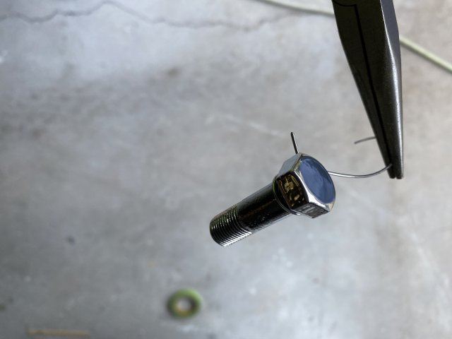
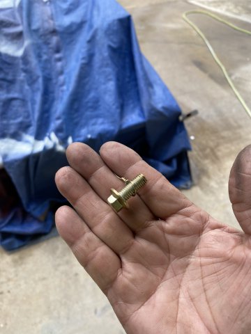
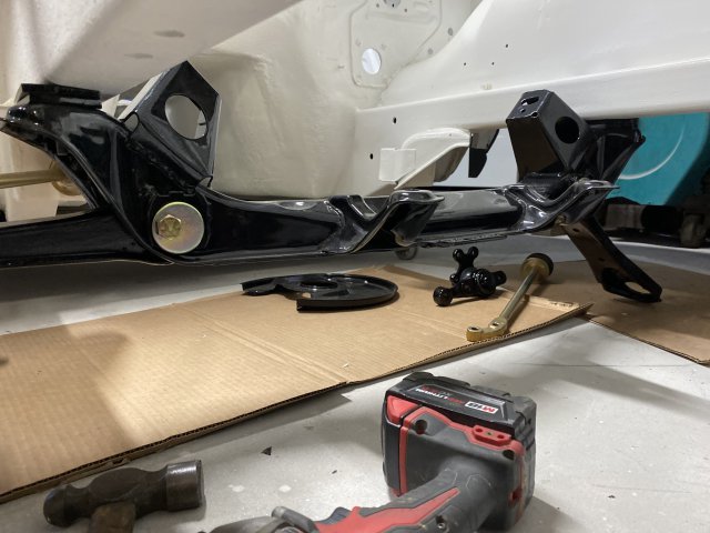
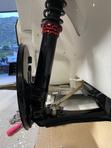
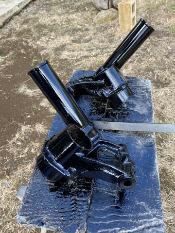
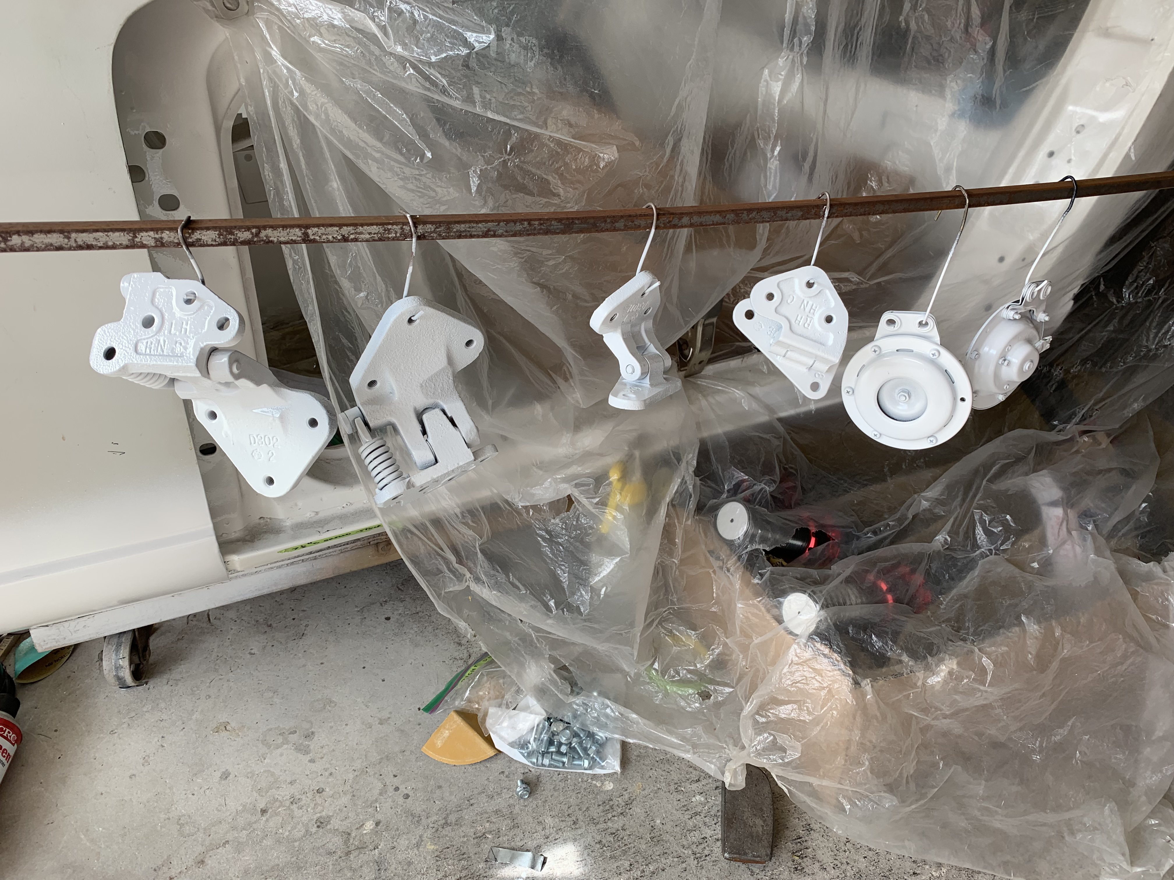
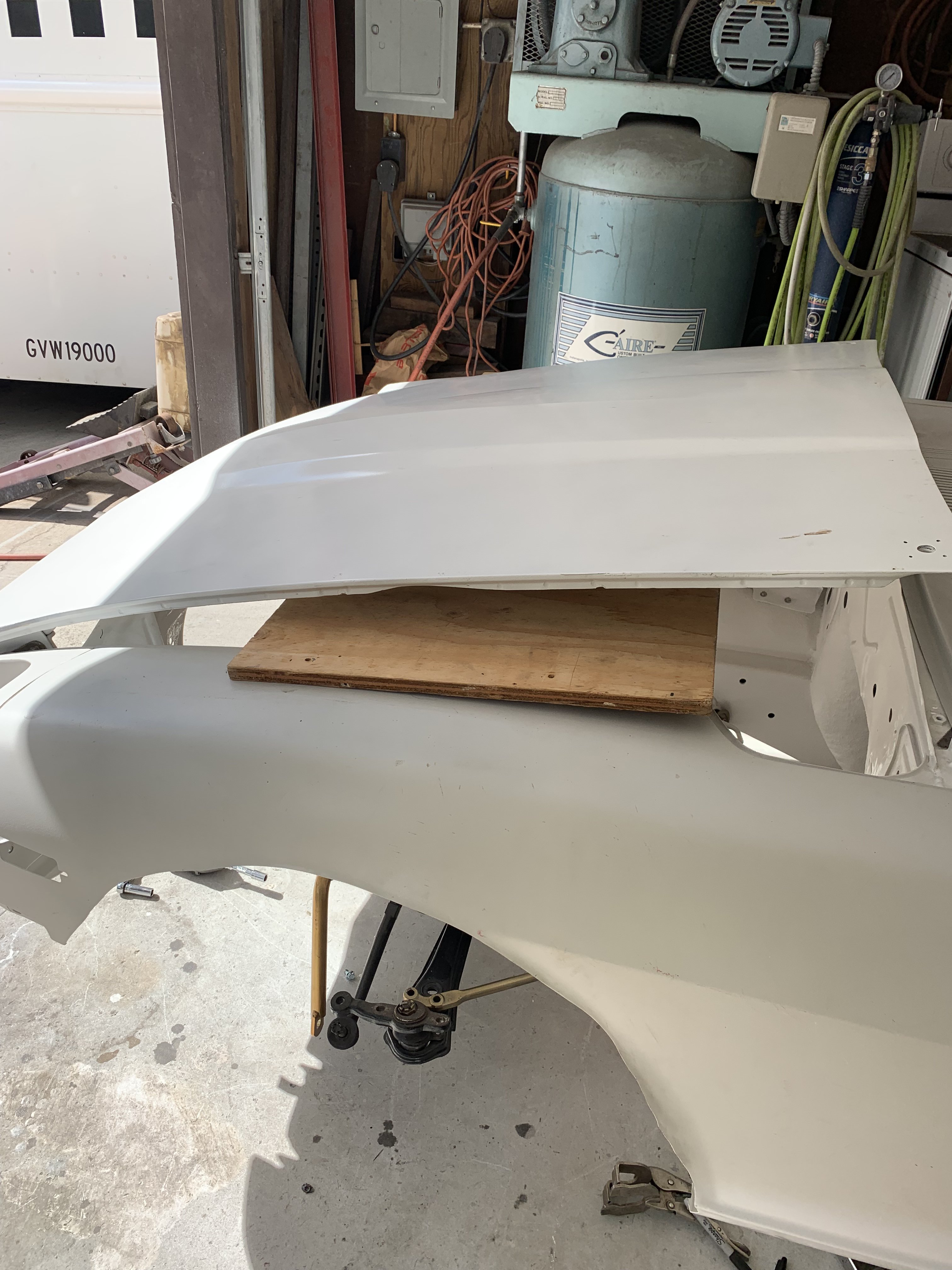
I had planned to work on installing the front suspension parts on my Z but I discovered that my supply of Gold powder was almost gone. So while I waited for the Gold Powder to arrive, I decided to finishing cutting the Right Front fender for the Rocket Bunny Flares. Like the Rear Flares, I made a Template of the already completed Left Front Fender. Note- I use almost all the fender edges( top, back, front and bottom) to create the template. The more reference points that you use, the more accurate the template will be. Side view of template Put template on the Right fender then Transfer the trim lines using a Black Marker pen. A Tin Snips was used to trim the fender. It was used as cutting thin metal like the front fender, vibrates a lot and making it hard to control. Note- make sure to grind all trimmed edges to prevent future sheet metal cracks. Next thing to do was to clean all of the Front Suspension parts in preparation for painting or powder coating. The rear stub axles were prepped at the same time to conserve paint materials. All the parts were first cleaned with cup wire brush on a 4 1/2 electric grinder to remove the heavy grease, dirt and paint. Then a Heavy Grease Removal soap ( was used straight without dilution) was used. First, with the parts cleaning brush then with a air solvent gun shooting the degreaser( now diluted) to get those hard to get to areas. Blasting away Stub axles after paining with Black Polyurethane paint. Note- the rubber joint boots were masked off otherwise the axles would have been disassembled to remover them. The other suspension parts after Polyurethane Painting. Before Powder Coating After Powder coating A flange bolt powder coated Front crossmember mounted Note- new Camber adjusting bolts were installed. Front to rear view of Front Suspension. Note -The Powder coated parts gives a nice contrast with Gloss Black suspension parts. Side view of the Right Side Suspension It took a lot of cleaning, grinding, painting and powder coating but I think it was worth it. Next, installing the Wheel/Tire Fitment Tool on the Front Suspension to check it out, is next.
-
Heavy Duty frame rails and connectors
toolman replied to toolman's topic in Gen III & IV Chevy V8Z Tech Board
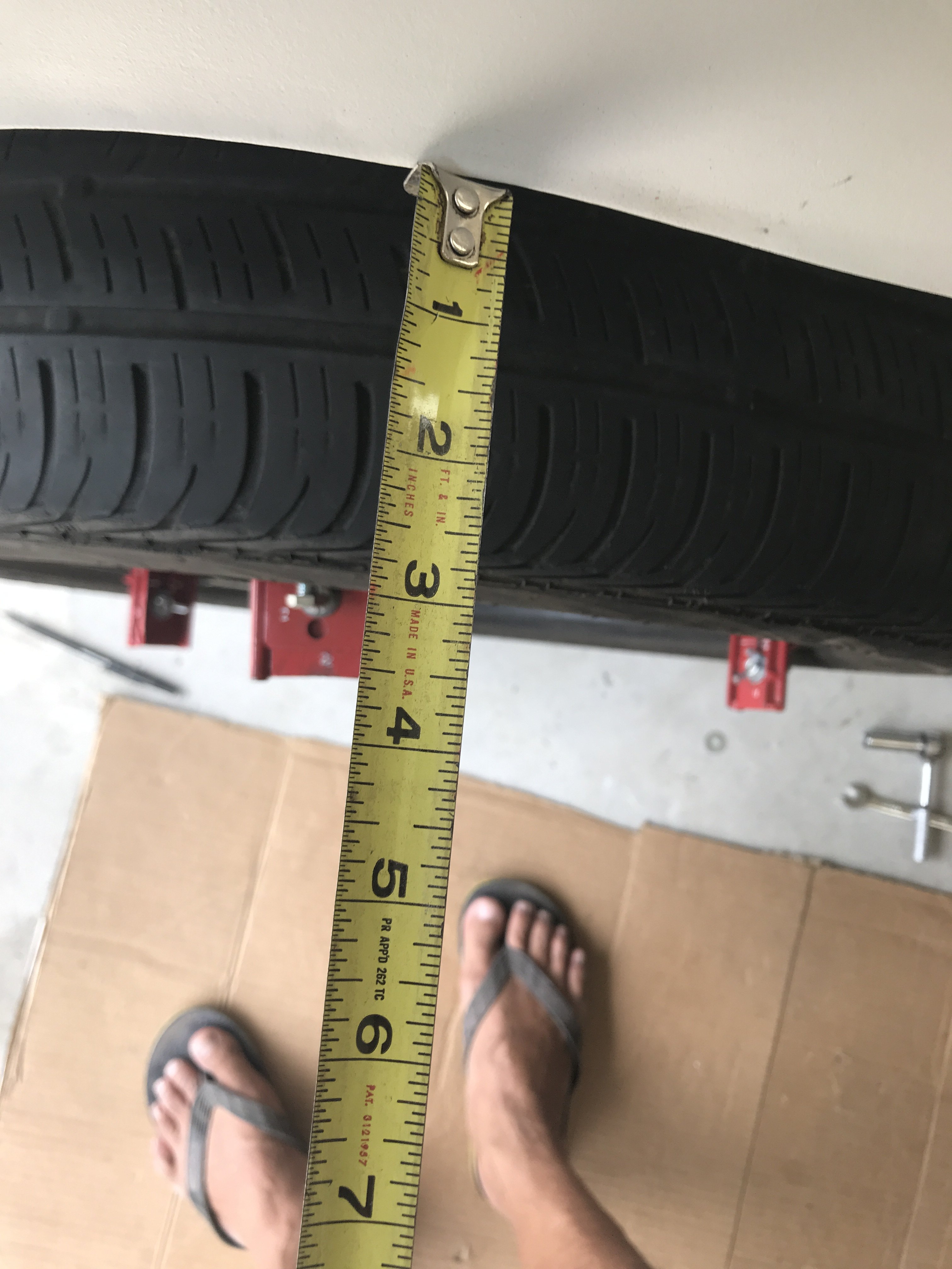
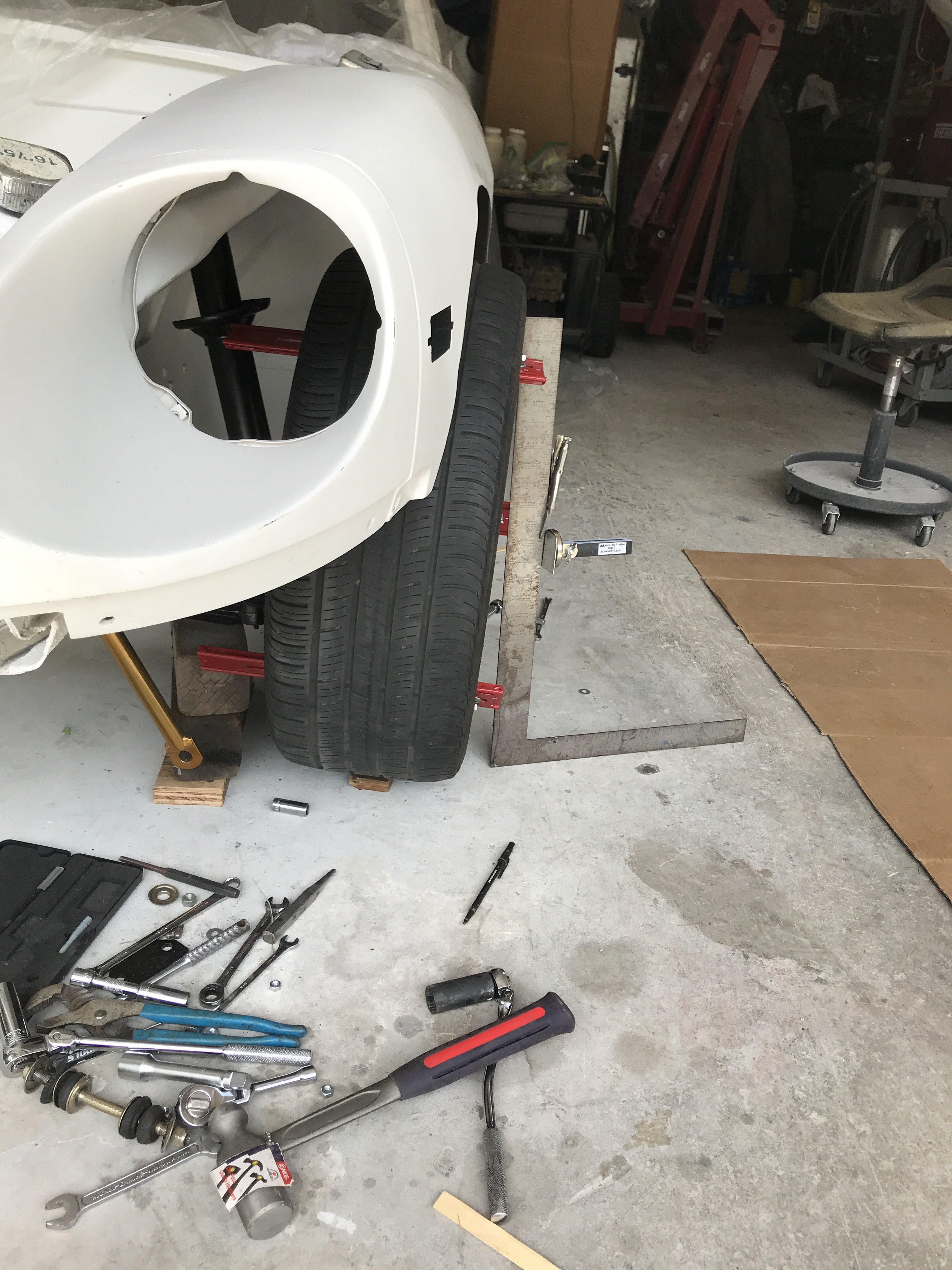
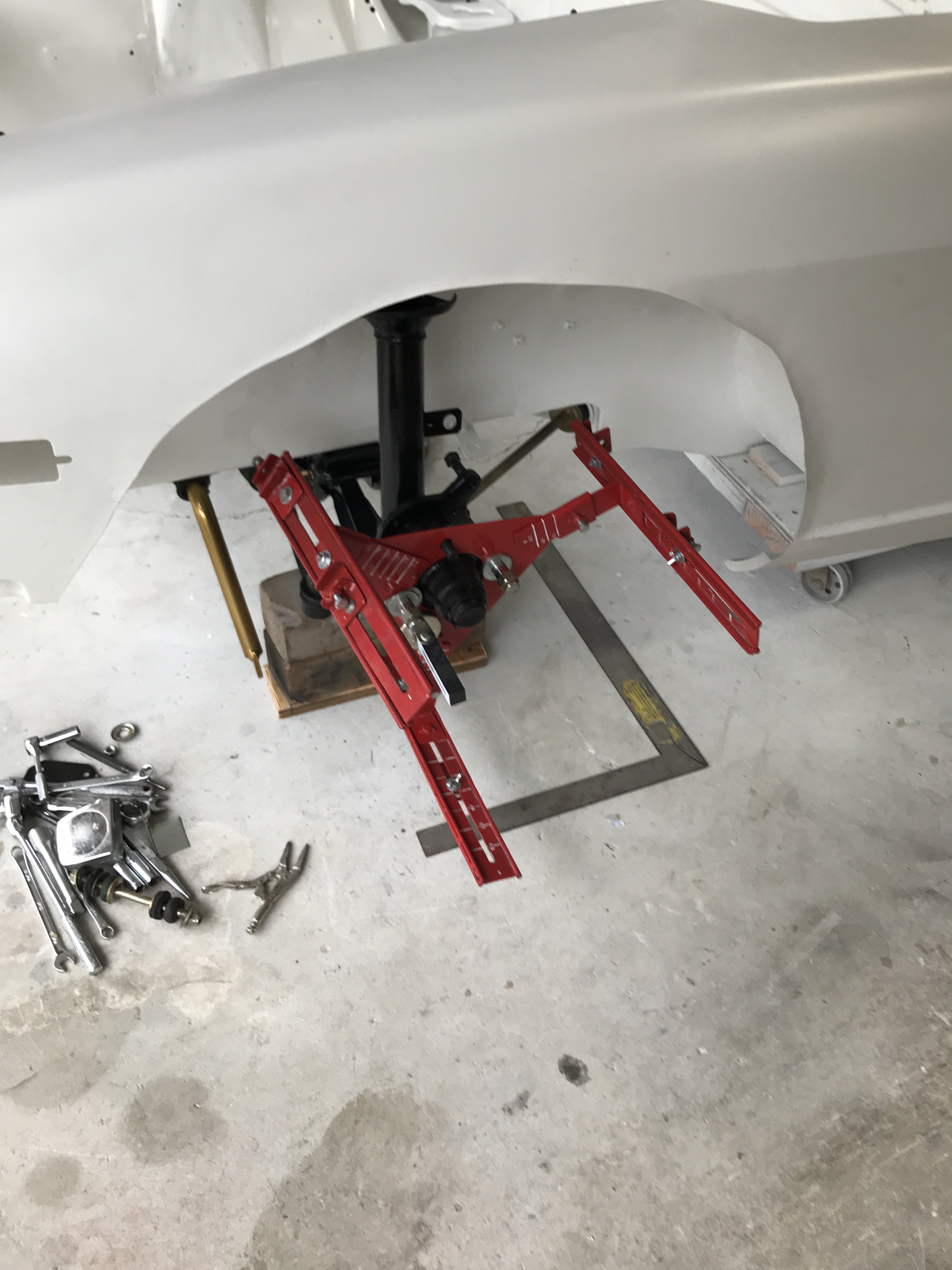
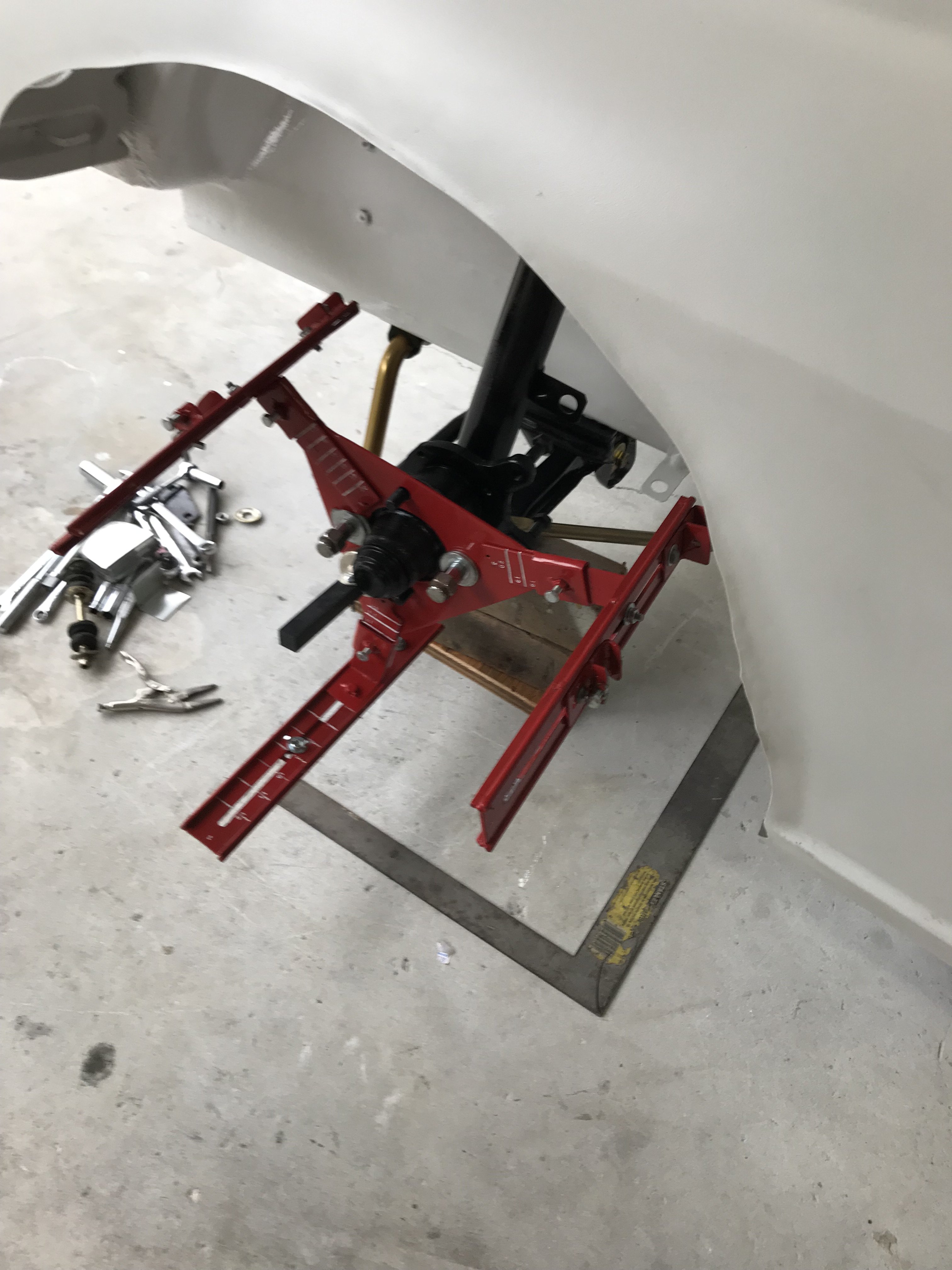
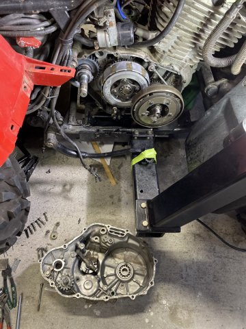
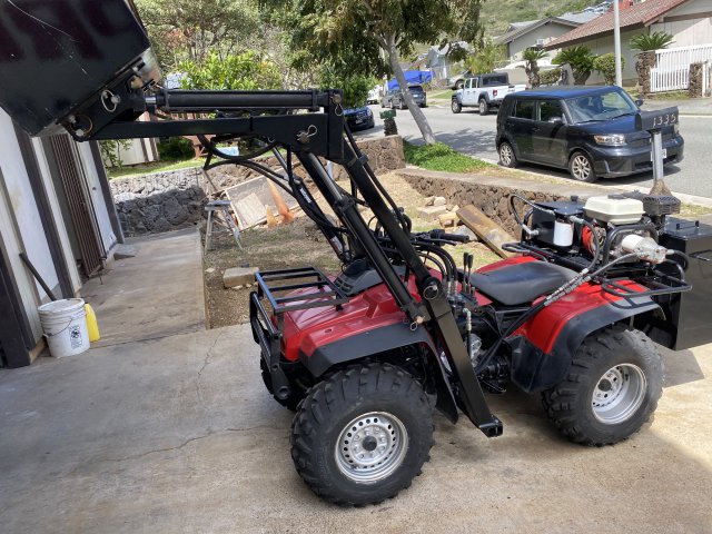
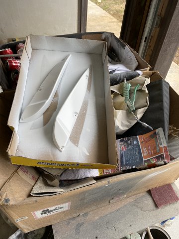
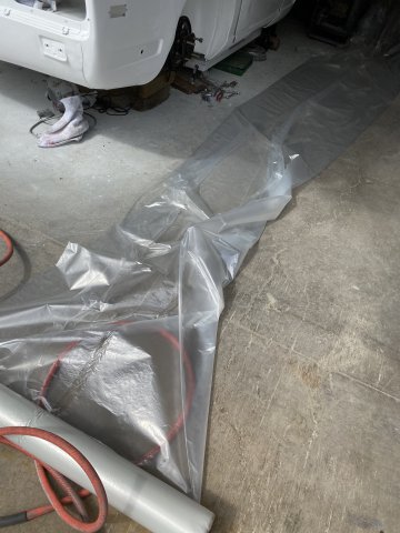
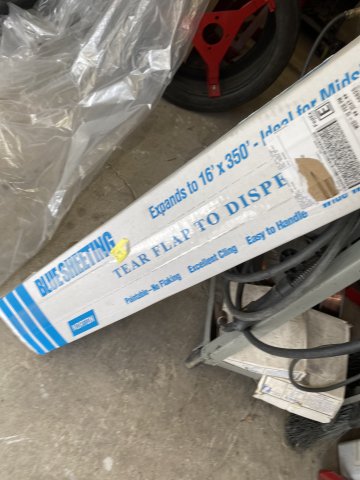
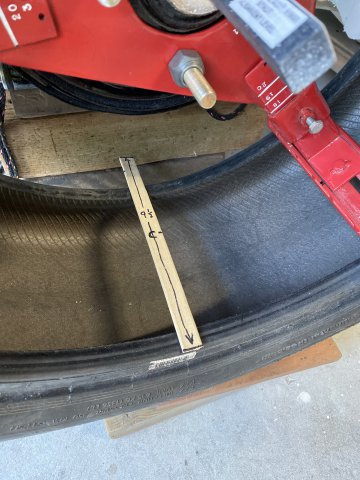
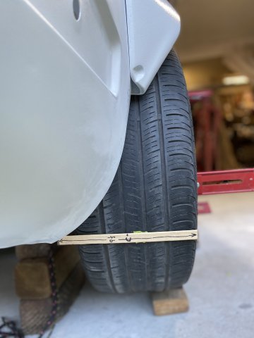
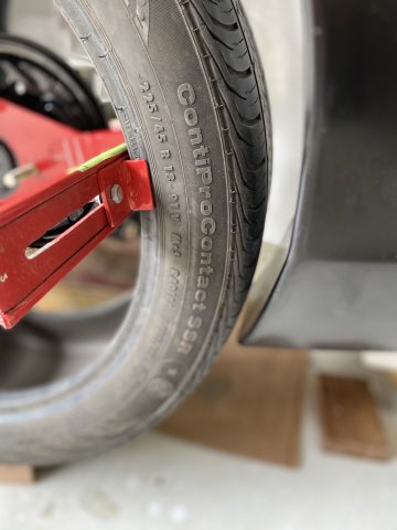
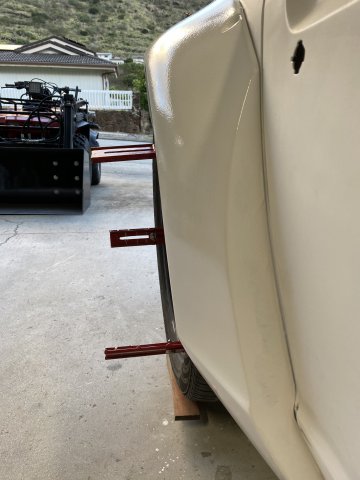
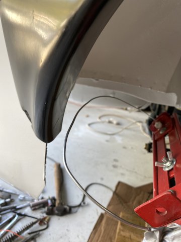
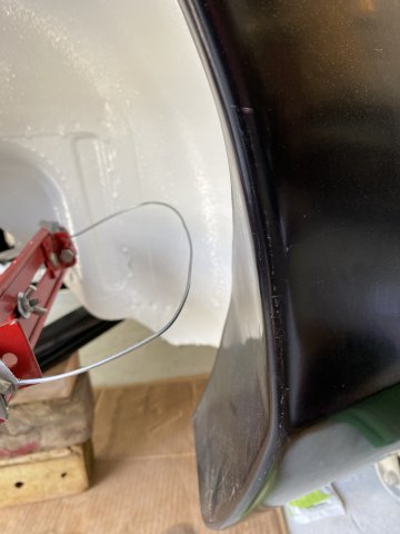
Sorry for the delayed reply. My 87 HONDA TRX350 ATV transmission shifter was jammed in gear. As it required me to split the outer left and right cases, the repair took two days to complete. It had to be repaired as it occupies the garage opposite of the 240z and there would be no space to work. This Front Loader Conversion to my Honda ATV was done before I started the 240Z restromod. I scratch built on a 87 HONDA TRX350 ALL WHEEL DRIVE ATV IN about a year ago. It can lift 400lbs in the loader bucket and has a 30 gallon water tank in the rear for ballast. The conversion was made to be Bolt On Accessory and can be removed in about 30 minutes. Now back to the Z Project. All Four of the Flares were painted inside and out with Polyurethane Primer. Had problems removing silicone from the mold release on the flares. Had to use Wax and Grease Remover and HD Water base soap several times to get the silicone off. Due the Windy conditions, I had to paint the parts in garage so had the cover the 240z with Plastic Sheeting to prevent overspray. The Plastic Sheeting can be gotten from automotive paint suppliers. Wheel Fitment Tool Finally get to use the Wheel Fitment Tool that was made coupe of months ago. This was the closest size tire that I could find to use-225x 45x 18. The wheel that I will be simulating is Rota RKR 17 x 9 1/2 with 20mm negative offset. As the sample tire is not large enough, it will be used with the majority of the tire will be facing outward to check fitment. As I running lowered coilovers, the inner clearance with strut is not a problem. First, install the Fitment tool with two lower legs set to 18 " diameter and third leg retracted. Now, adjust the two lower legs tire width adjustors to fit securely. Now, Adjust the upper third leg to obtain the 18"diameter and adjust the tire width adjusters for a snug fit. The only wheel that I found that had specifications came close was ROTA RKR 17 x 9.5 with -20MM offset. I put its specifications on a wooden paint mixing stick. Remember that this tire is only 18" so the 9 1/2 tire will stick more inward. This stick show the wheel offset. The "C" line indicates the center line of the Rota wheel. The inner end of the stick indicates the width of a 274/45 tire. Front tire clearance shown Front to rear view Side View of the Wheel/ Tire Fitment Tool on the car. As the car is on a dolly and there is almost no weight in the car, something had to be done to set Ride Height. So I removed the upper strut spring section to allow upward movement of the suspension. I set the ride height setting the center of the wheel hub to the lower body line of the car. From most pics of street driven lowered 240z cars, the center of the rear hubs were in line with the body line. This is not perfect way but I think it is close enough to demonstrate ride height until I can actually load the suspension after the complete swap. For those of you, that wanted more tire fitment information, I bent a 1/8" wire shaped to match the tire cross section that you wanted to check. In this case, a 274 x45 tire cross section was created and bolted to one of the wheel legs. . You just rotate the simulated tire cross section to check any clearance issues with body and strut. Check Front Clearance of the flare. This rear view demonstrates what a 274 tire would look look like. Remember the 275 tire would extend to the end of the stick or about a inch more inward. The next thing to do is to put the Tire/Wheel Fitment Tool on the front suspension and see what tire/wheel combination could work on there.
-
Heavy Duty frame rails and connectors
toolman replied to toolman's topic in Gen III & IV Chevy V8Z Tech Board
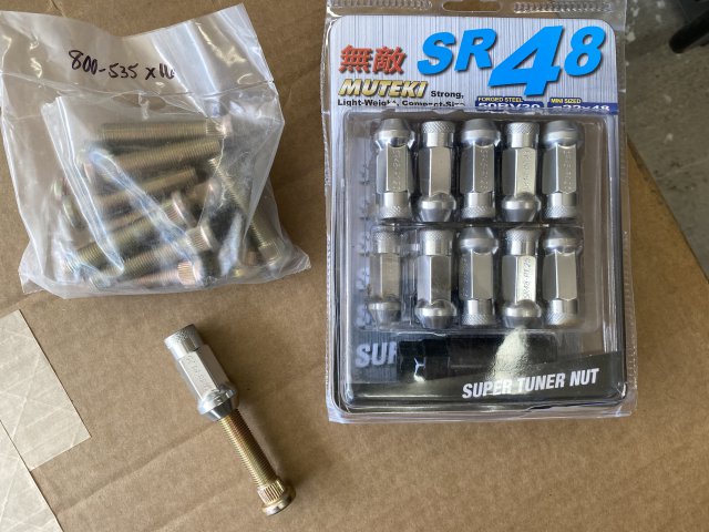
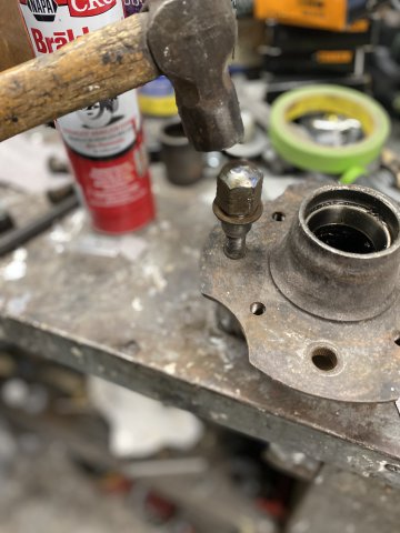
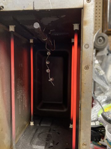
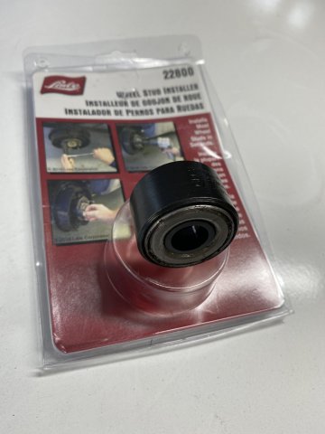
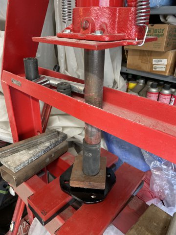
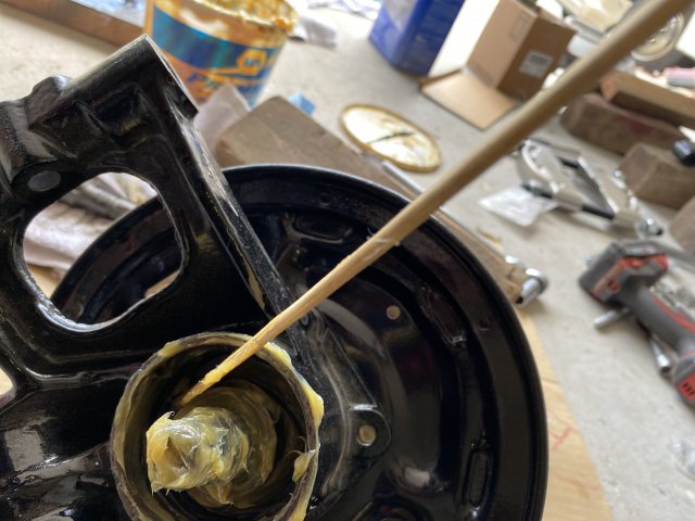
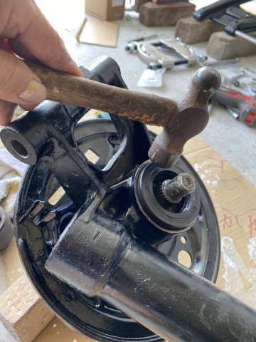
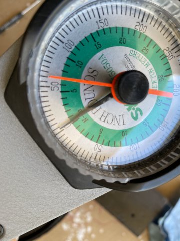
Rear Suspension Overhaul: A Threaded Steel Rod with nuts and assorted washers were used to install rear control arm outer bushings. This method was used because although slow, it has less chance of damaging the steel metal bushing housing on these control arms. Ordered ZDepot 50mm extended wheel studs and Muteki extra long wheel lug nuts from EBAY. They maybe necessary to gain proper wheel fitment later. The old wheels studs were removed by hammering them into the large metal tube. Hub parts were powdered coated. Lisle Tools Wheel Stud Installer only requires a 1/2 impact gun and lug socket to install the new wheel studs. The Hub Outer Bearing was pressed on the hub. The Outer Hub bearing was then packed with grease. The whole assembly was pressed into the strut housing. Now, by looking into the inner bearing bore-check the two casting cutouts to determine if the bearing is properly seated. After which. the bearing cavity and spacer is packed with grease. I used a paint paddle to spread the grease into the cavity. The Inner Bearing(non sealed one) is packed with grease. To install this bearing, you can use the old bearing to tap the new one in. Don't worry the old one won't get stuck in. Keep tapping it until a solid feeling and sound occurs for proper seating. id Coat the inside of the seal with grease especially the seal lip. Tap the seal with hammer( can use old bearing also) to about 3/16" below edge. Then, the flange. washer and locking nut are installed. A Dial !/2 Torque Wrench was used to torque the Locking Nut. Specifications call for 180 to 250FT LBS. The reason of the range is the Bearing Preload cannot be determined by Foot Pounds alone. So you slowly torque to 180 ft lbs then check turning torque and keep doing this till everything is right. The Hub Shaft nut turning torque is about 4 inch pounds. The shaft endplay is 0 to .0059. You will need a Dial Indicator to do this but not necessary. So you try to achieve all these parameters to get a accurate bearing preload. 1/2 Dial Torque Wrench A Dial Inch Pound Torque Wrench checking Turning Torque( about 4 inlbs) A Dial Indicator can be utilized to check for 0 to .0059" End Play After completing Bearing Preload, I flattened the Locking Nut tab to prevent the Hub Nut from loosening. Next, the Rear Flares will be attached. The Wheel/Tire Fitment Tool will be installed to check fitment issues.
-
Heavy Duty frame rails and connectors
toolman replied to toolman's topic in Gen III & IV Chevy V8Z Tech Board
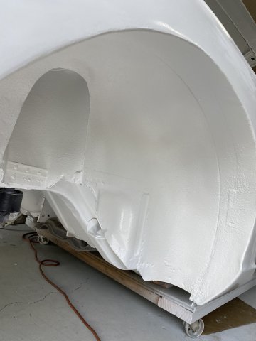
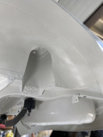
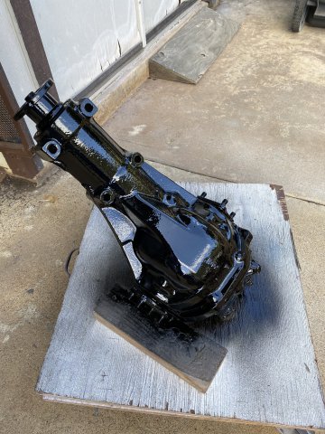
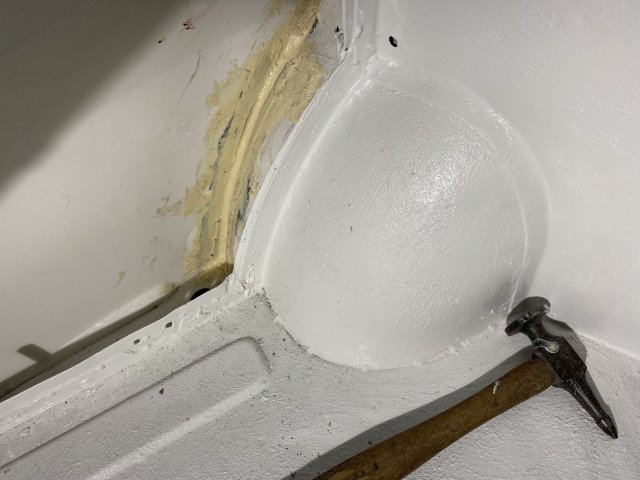
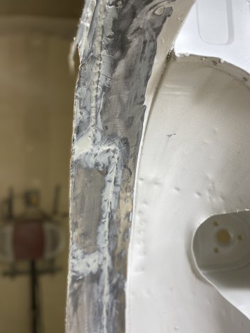
Richard, Thanks for complement. The cowl area was masked for seam sealer spraying for added protection. Sem Products Sprayable Seam Sealer Using Sem Sealer Spray Gun Central cowl area sprayed right side of cowl Left Rear Wheel Housing interior area sprayed. Seam Sealer was sprayed in between the quarter panel and wheel housing area( the patched area) too. Note-the 3/16" steel rod between the quarter panel and wheel housing can be seen. This view shows seam sealer coverage on the inside of the front of the wheel housing. View of the bottom of the fuel filler area sprayed. Upper area of the fuel filler area. Note-the back side of the fuel filler compartment was also sprayed. The Right wheel housing was sprayed with White Raptor Bedliner after Fusion Seam Sealer was applied over all patch seams. Front view of Right Wheel housing sprayed. Right rear Wheel housing sprayed. Pic of my garage work area. Suspension parts painted with Gloss Black Single Stage Polyurethane Paint on my driveway. R200 differential was also painted. Rear Strut housing painted. Next thing for me to do is replacing bearings and bushings suspension parts and the reassembly begins.
-
Heavy Duty frame rails and connectors
toolman replied to toolman's topic in Gen III & IV Chevy V8Z Tech Board
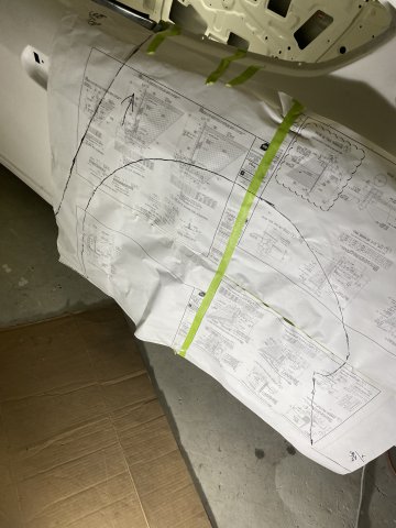
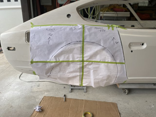
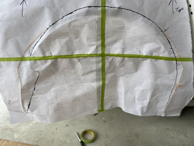
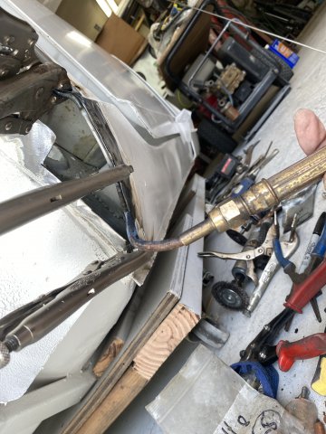
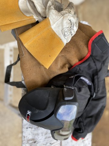
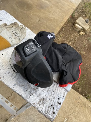
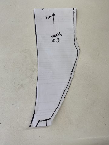
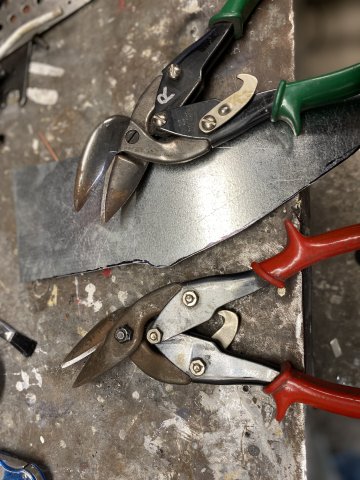
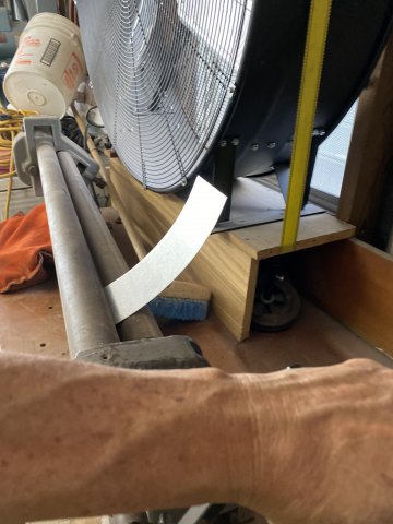
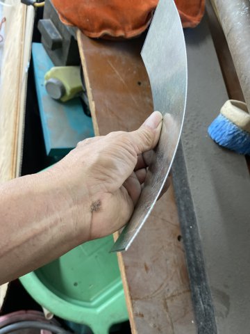
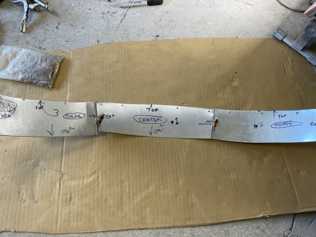
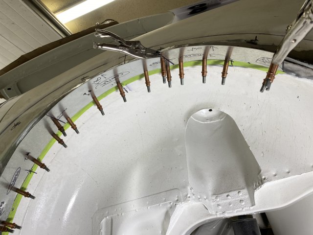
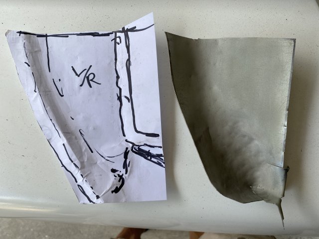
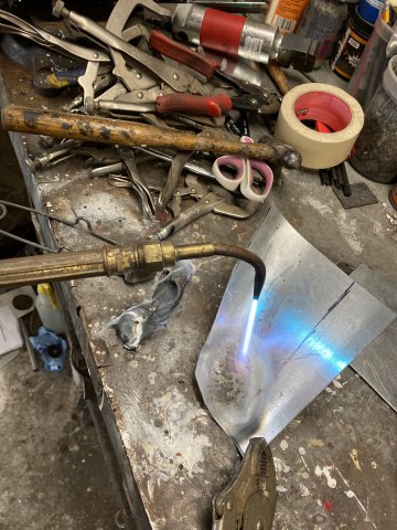
Replicating the Left Rear Wheel Housing to the Right Side. To do this task, will require making a paper template of the newly modified Left Rear Flare opening. A large piece of paper was placed over the L/R flare opening. The major reference lines to be traced are: #1 The Front Edge of the Rear Quarter Panel. #2 is the Wheel Well Opening Edge. The distance between the Top Center of the Wheel Opening to the one of body holes for mounting the Rear Quarter Glass. The measurement will be the height of the flare opening. You may have to darken your Guide Edges if their ink is not visible on the opposite side of the template. Remember you have to use the opposite side the template for the correct orientation. Using the edge guide line and height measurement to align the template on the Right Side. Make sure to securely tape the top edge of the template to the quarter panel as you don't wanted the pattern moving. The Orange Lines in this closup show the areas to must be filled in because overcutting from previous flaring. This provides pattern for the filler panels. Creating the Rear Filler panel. Note- guide lines help to keep filler aligned. The Front Filler Panel being created. Pic of the Inner Wheel housing to Quarter Panel Filler patch Template. To make this Flare Opening a little easier to weld the quarter panel and wheel housingtogether, 3/16" Steel Rod from Home Depot( $13 for 8Ft) was used. The rod would weld between quarter panel and wheel housing filler. It prevents burn through especially with .023 sheet metal. On the Front Side of Quarter Panel (Dog Leg Section), there are some curves in the panel so you must bend the rod to follow the curves. That task is accomplished by holding one end of rod with vise grips and using a torch to soften the 3/16" rod. Then bending the rod until the required shape is obtained. Note-I have used this technique of welding round steel rods around flare opening on many cars. You can use 3/16" to 3/4" steel tubing or even brake lines to outline the tire openings. But solid steel rods don't kink like fuel lines would This method really reinforces the edge and prevents tire damage in case there is contact. For those of you who are tired of getting burnt by hot sparks while welding in confined areas, I would recommend getting this welding gear. The Tight Fitting Welding /Grinder Automatic Darkening Hood Gear. Regular Welding Helmets were never made for tight confined areas. After trying this welding gear at the Sema Show, I ordered one for myself. The Rear Filler Patch mig welded in place. Pic of the Front Wheel Housing patch template. This patch was created using Left and Right Cut Tinsnips. They make cutting curves easy. Front patch after hammering and metal shaping. The area to be filled in. Patch test fitted. Top Wheel Housing Filler patch Rear Wheel Housing Patch Rear Housing Filler patch The Next Thing to do is spray Raptor Bedliner over the inner wheel housing for extra protection. Then Top Coat it with Single Stage Polyurethane paint.
-
Heavy Duty frame rails and connectors
toolman replied to toolman's topic in Gen III & IV Chevy V8Z Tech Board
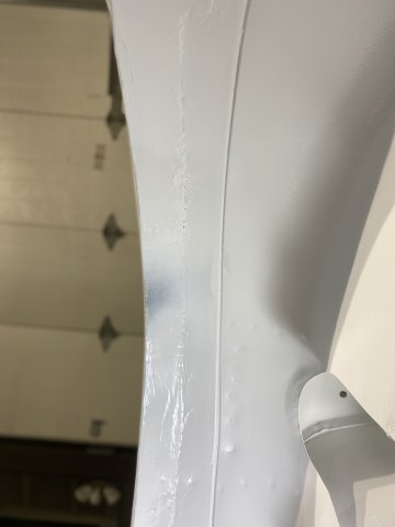
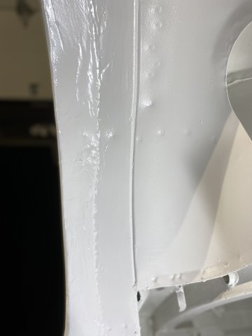
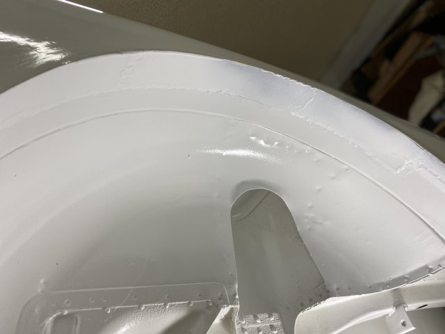
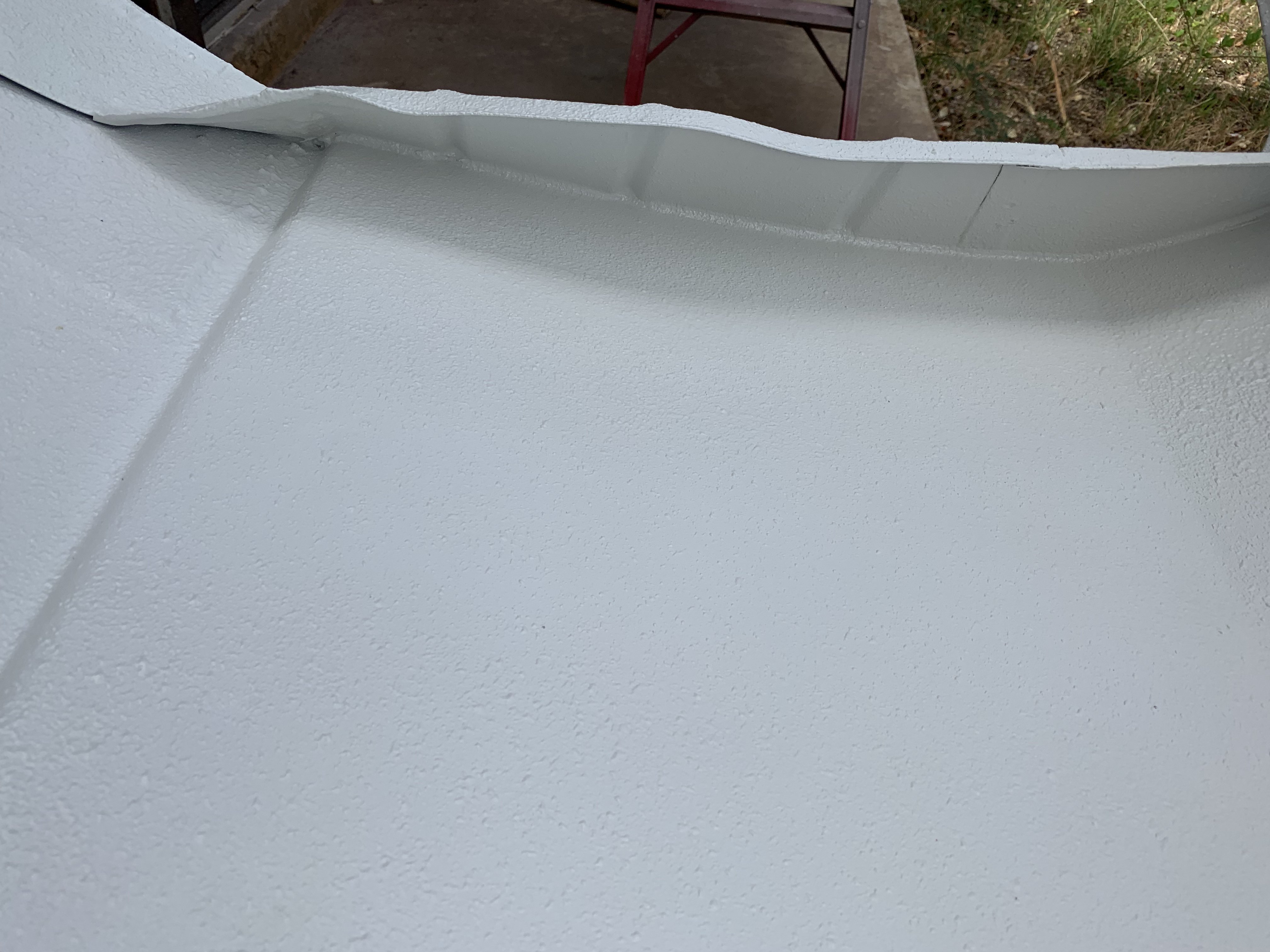
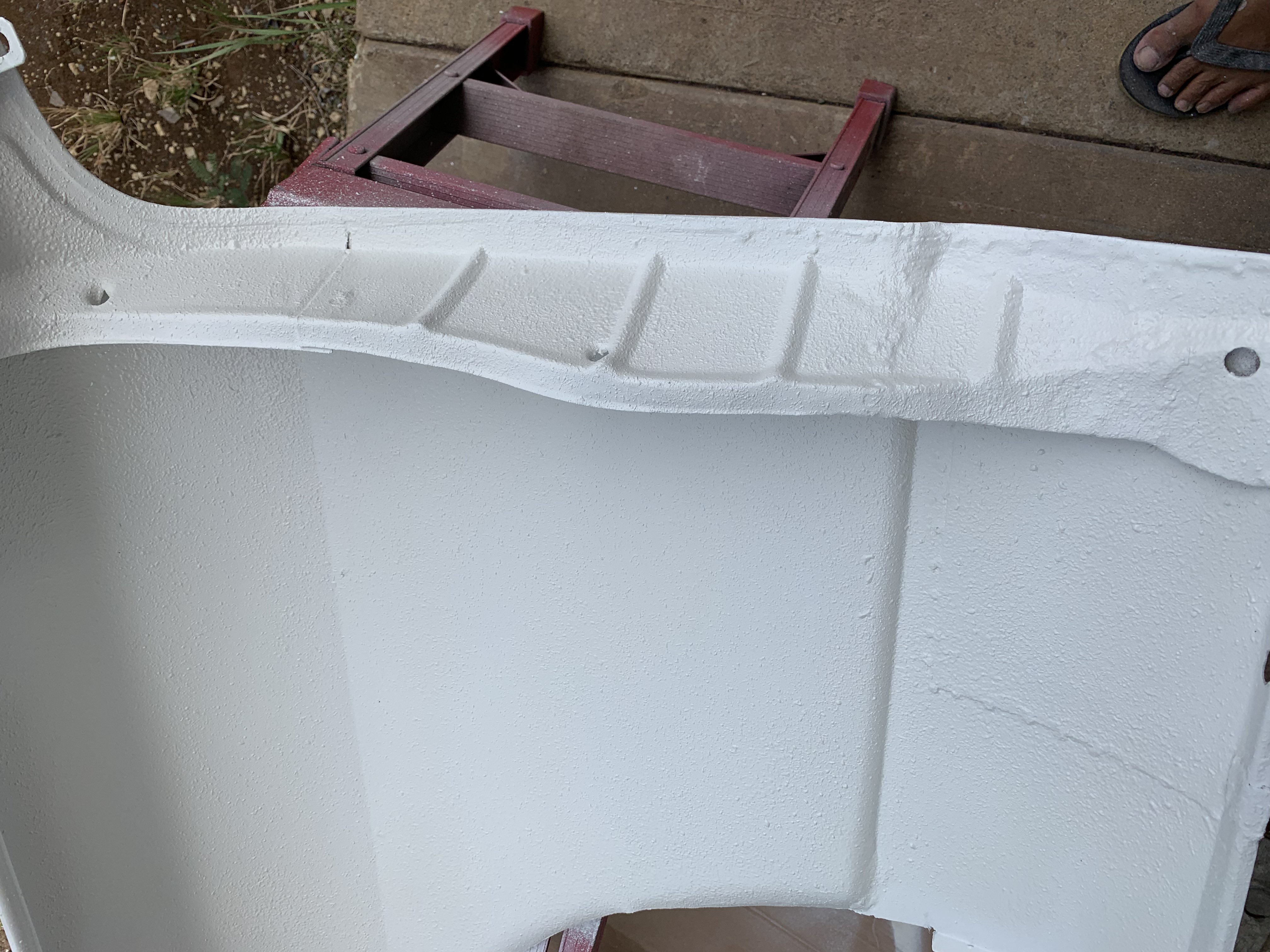
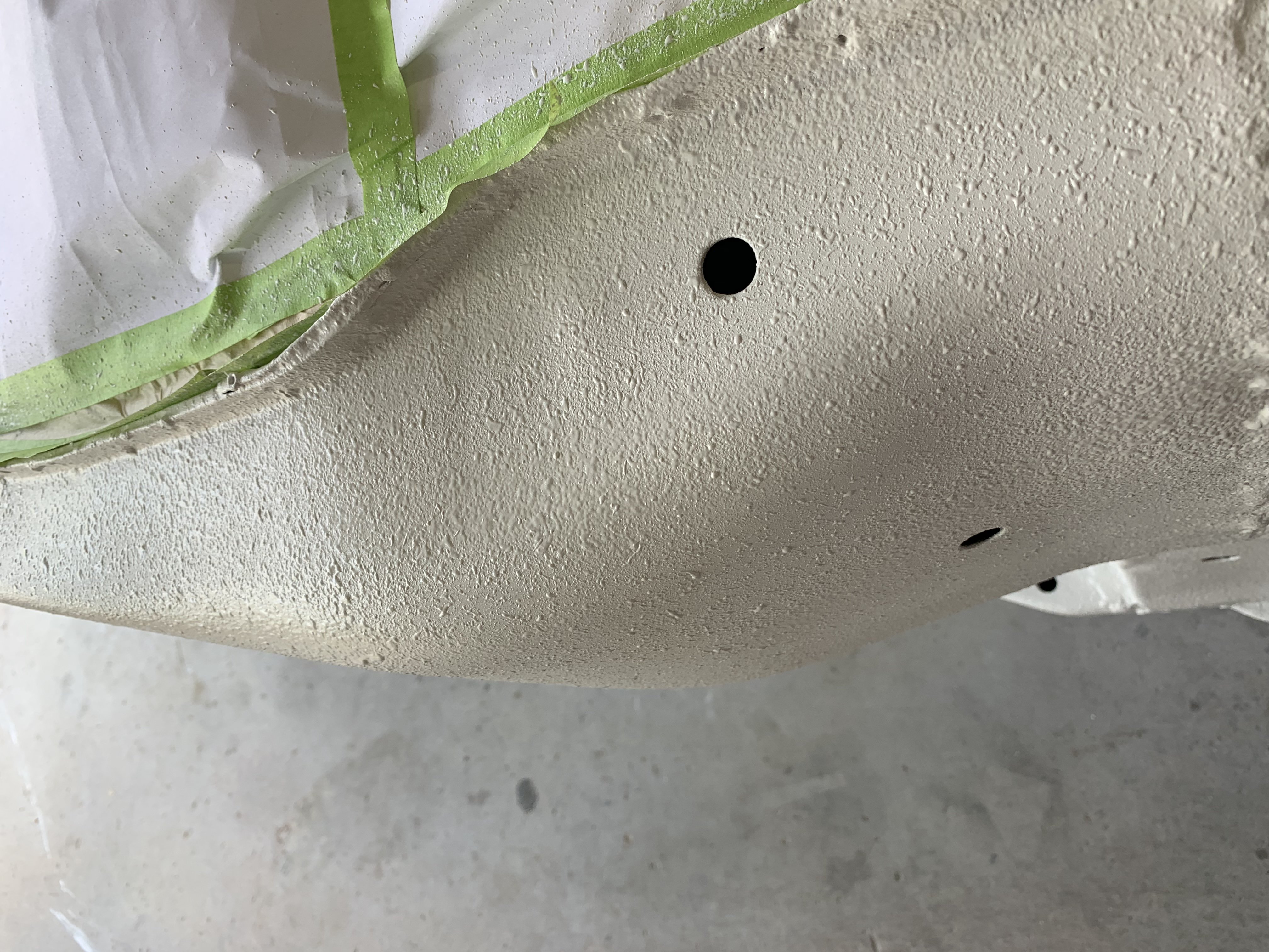
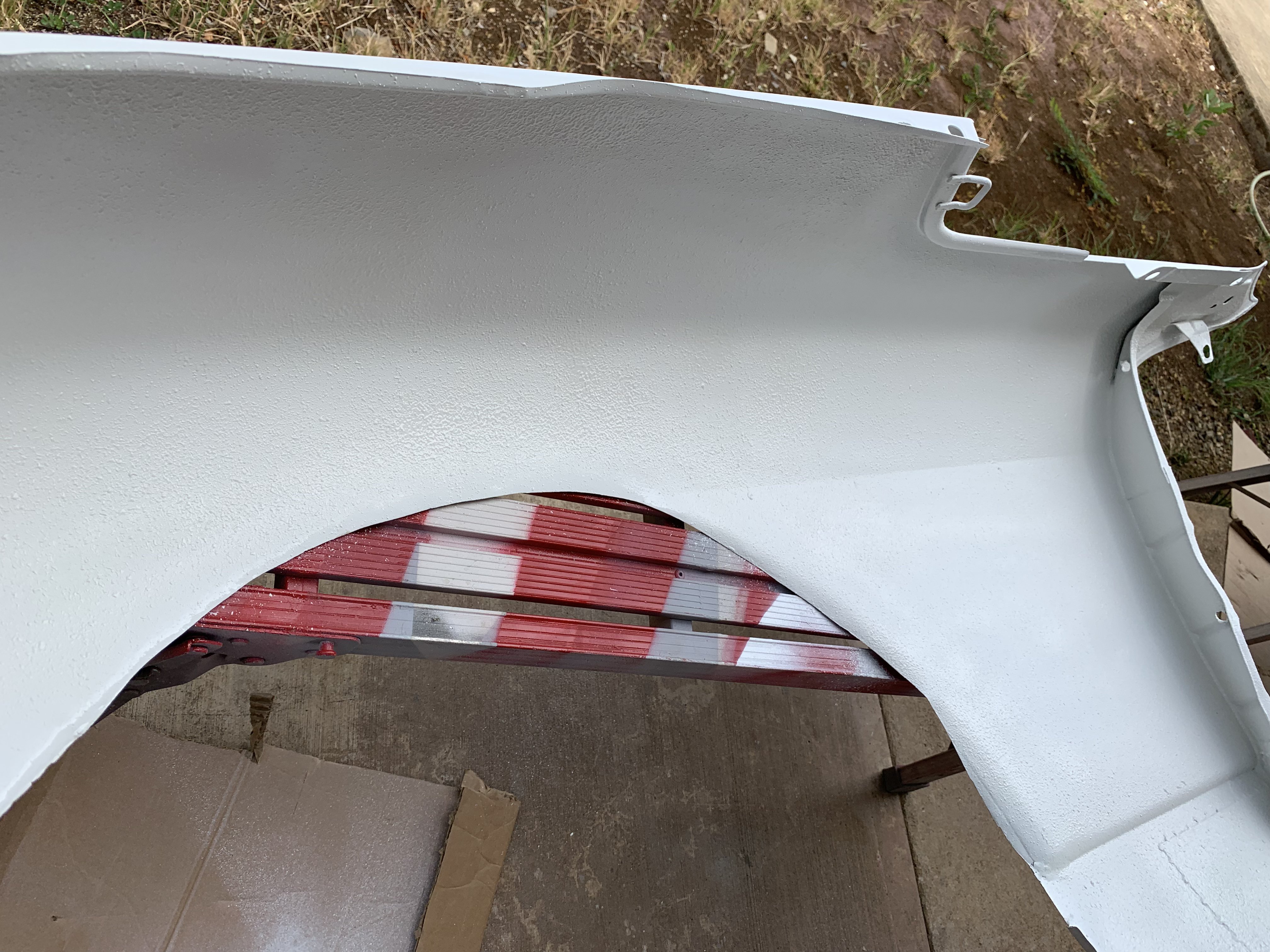
Thank you Nelsonian, Here are additional pics of flaring modifications. After sealing the inner top section of the wheel housing, area was painted with polyurethane paint. Bottom view of wheel well housing after painting. Overall view of rear flaring modifications
-
Heavy Duty frame rails and connectors
toolman replied to toolman's topic in Gen III & IV Chevy V8Z Tech Board
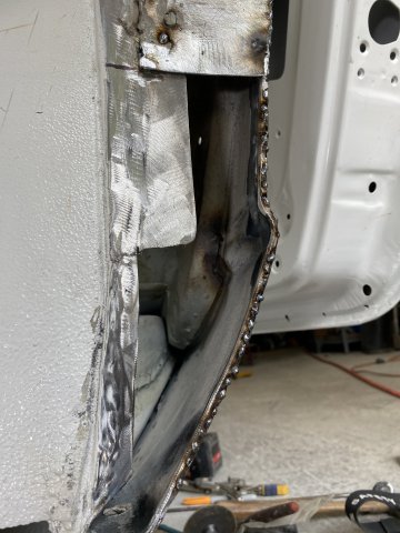
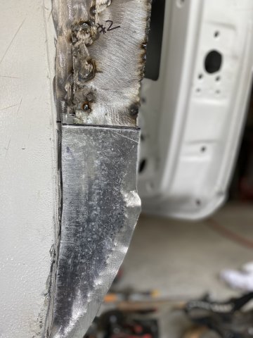
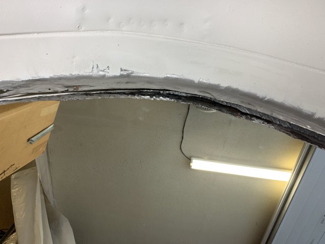
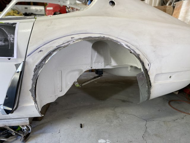
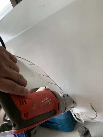
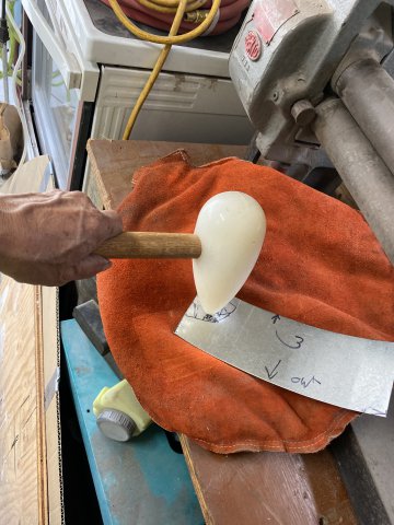
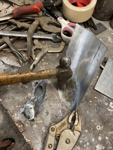
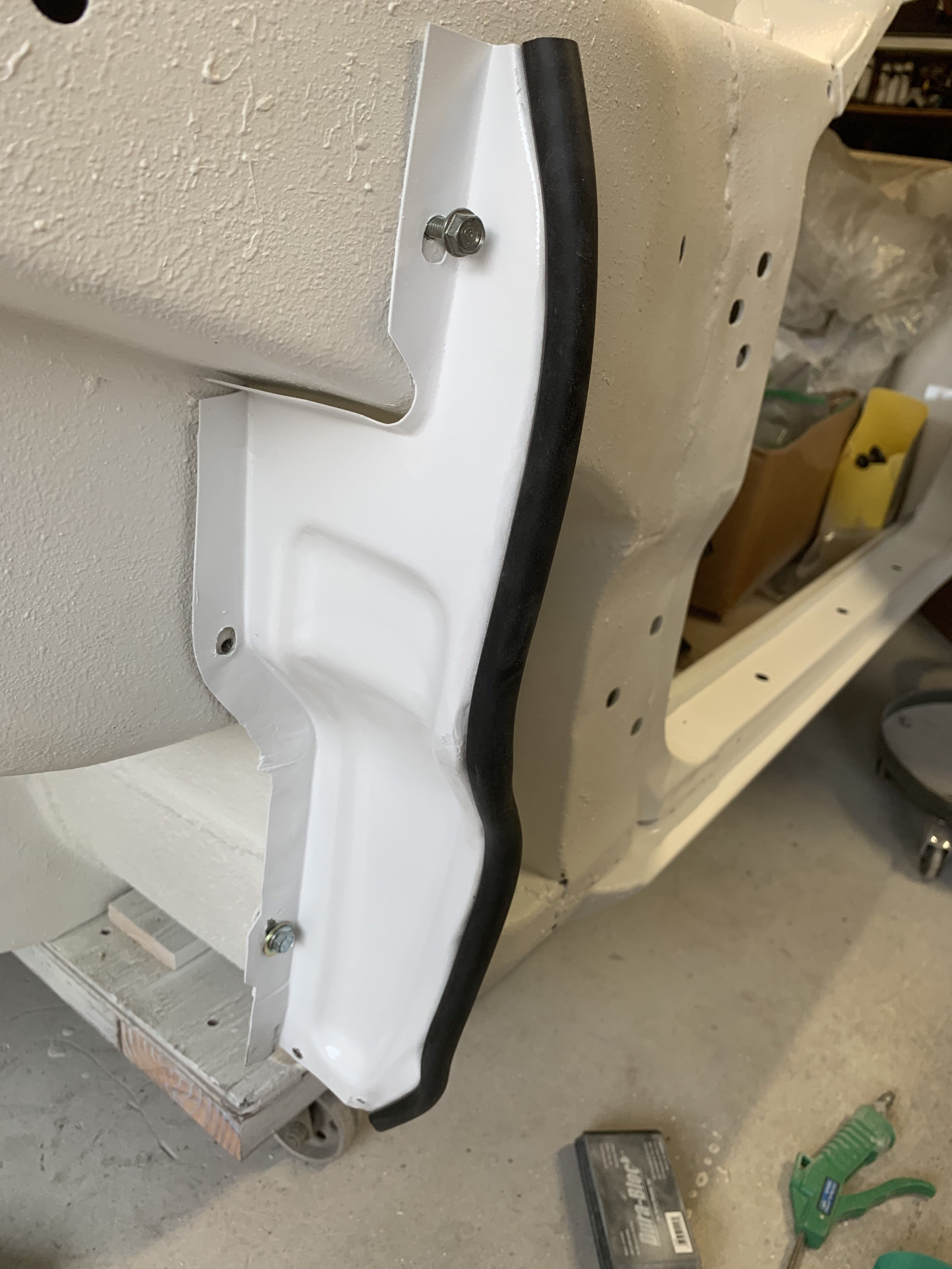
Left Front Fender modifications for Greddy Flares. After placing Rocket Bunny flare against the fender then mark the area to be removed with a black marker pen. A Electric shears was used to cut the major removal cuts. Always cut carefully to prevent "over cutting too much". A Hand Nibbler was used in the Finishing Cuts. The Finished Product Rear Wheel Housing Modifications for the Rear Flares- Like the Front flare. the Rear Rocket Bunny Flares are mocked against the existing quarter panel. The Outer edge of the flare is marked with a Black Marker Pen. In my case, I had already removed the original wheel opening edge when I constructed metal flares previously, there was a little less of the quarter panel to remove. Bottom view of the wheel well(looking upward from the ground) As the photos show the gap between the quarter panel and wheel housing was only about 3/4". So I could have just squeeze both panels together and mig welded them together. But I decided to cut an additional 3" higher to give more tire clearance and allow more body drop. Better to do it now instead of later. Side view of additional cutout. But now, the gap between quarter panel and wheel housing increased by about 2 1/2". So fillers had to made to fill these gaps. Patch being mocked up. The Sheetmetal Roller was utilized roll the metal to match the wheel housing. making gap fillers Overall view of the gap fillers An Air Punch/Flanger is used to flange the edges of the fillers to make the filler surface smooth and stronger. Cleco pins and vise grips hold the gap filler plates in place for welding. The front of the Left wheel well housing needed a patch so a paper template was created. Note- the bottom of this patch had to be "rolled over" by making a slit on the bottom then hammer welded the slit closed. The patch started as a flat piece of 20 gauge sheet metal that heated with a torch to soften it. Then was hammered with a Shaping Hammer on a Leather Shot Bag to shape the patch. Additional pounding with a Ball Peen Hammmer. The Patch fitted into place then tack welded in. The inside portion of the wheel well patch was covered with Fusor Seam Sealer. Inside of the wheel housing, EverCoat Epoxy Seam Sealer was applied over all welds and all seams. Polyurethane paint will be spray painted over all of the repaired areas. The inside wheel well areas will also be covered with Urethane BedLiner for additional protection.
-
Heavy Duty frame rails and connectors
toolman replied to toolman's topic in Gen III & IV Chevy V8Z Tech Board
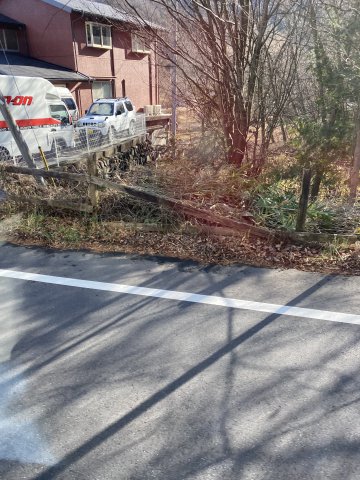
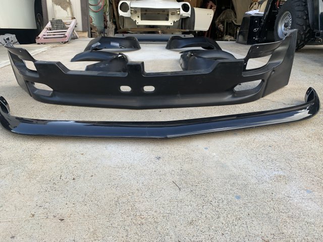
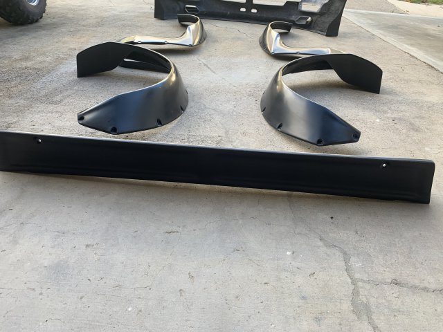
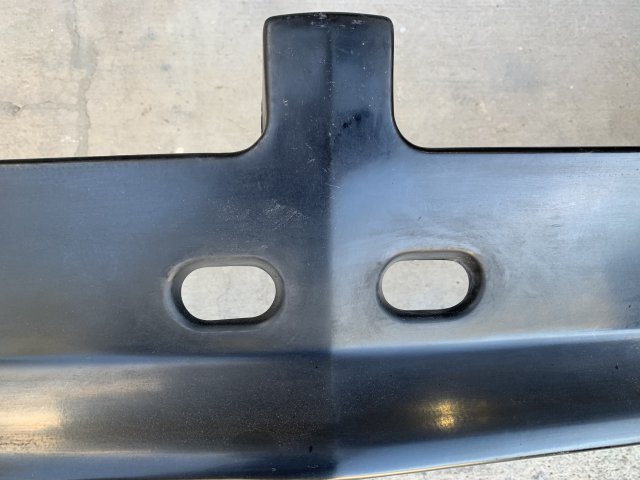
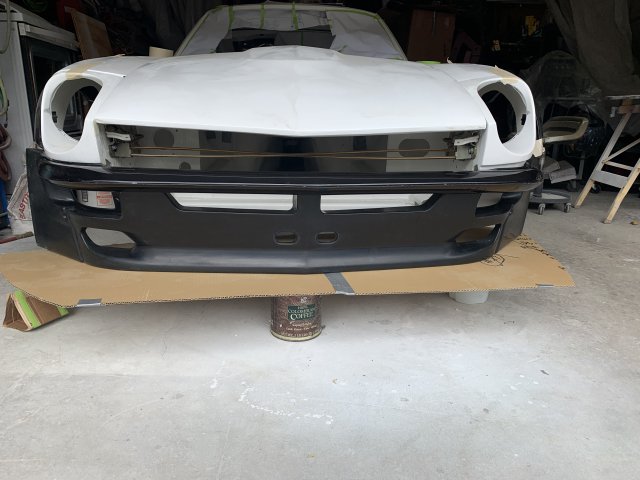
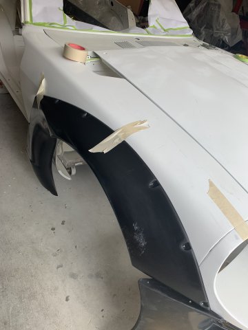
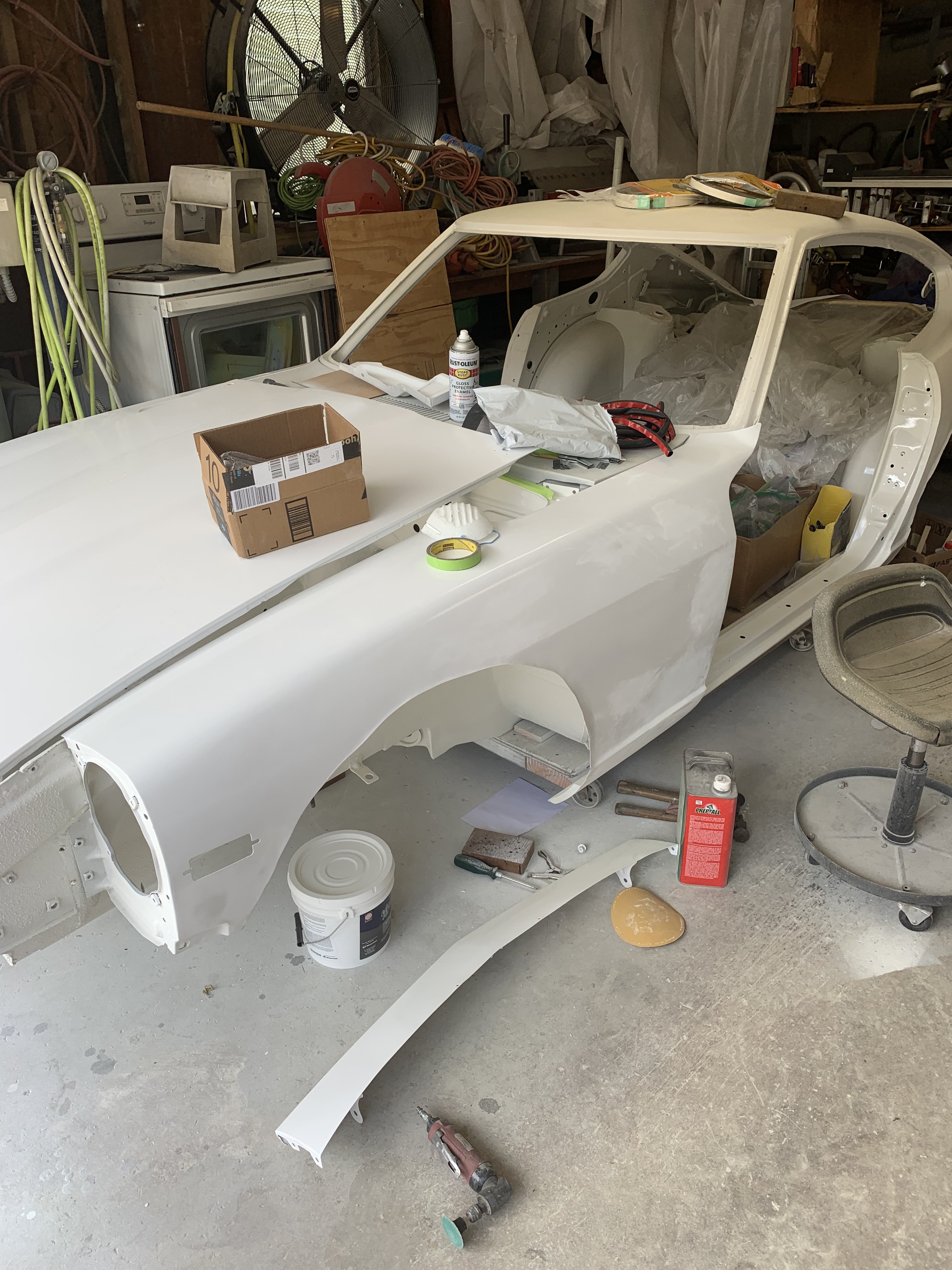
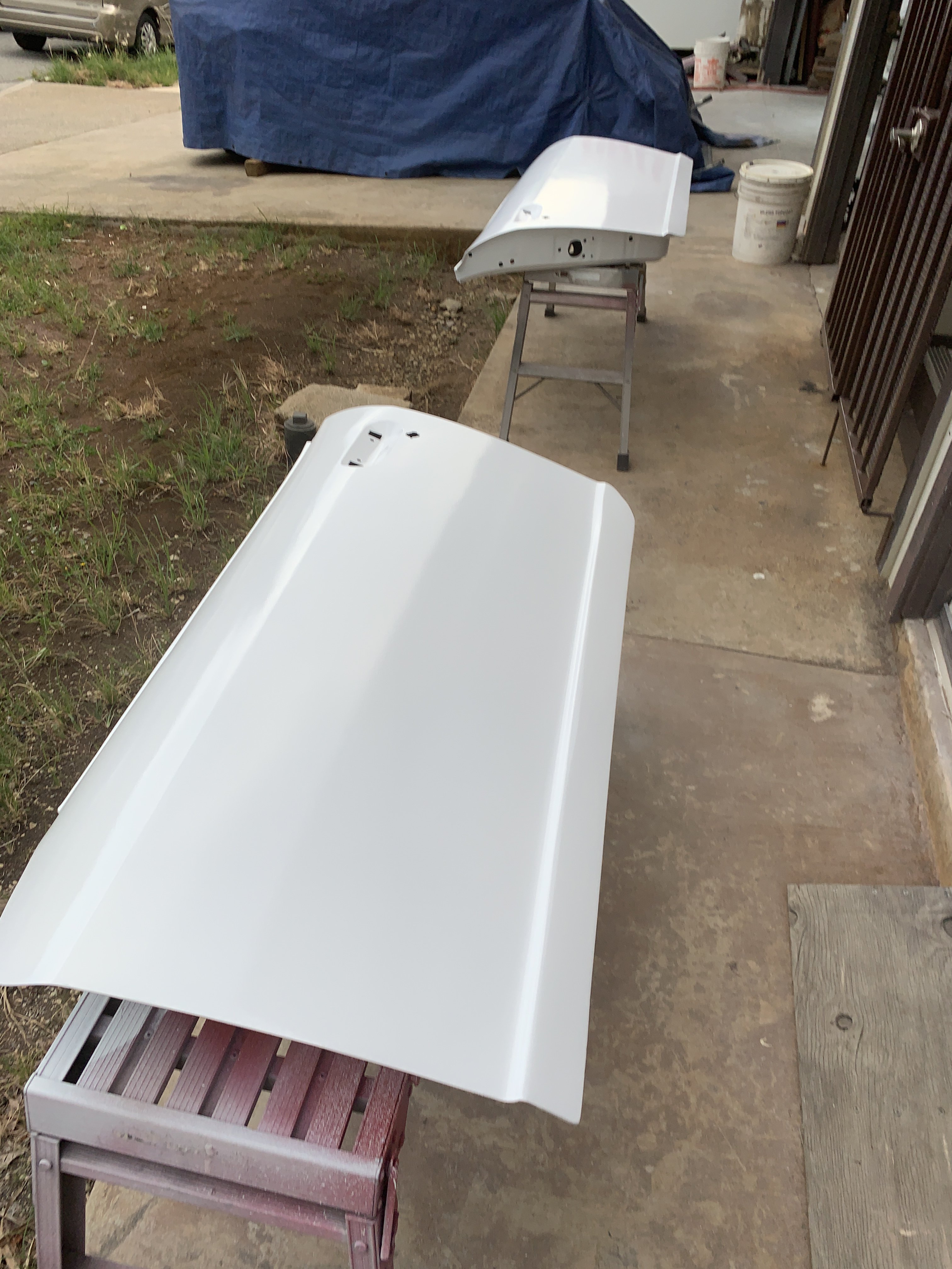
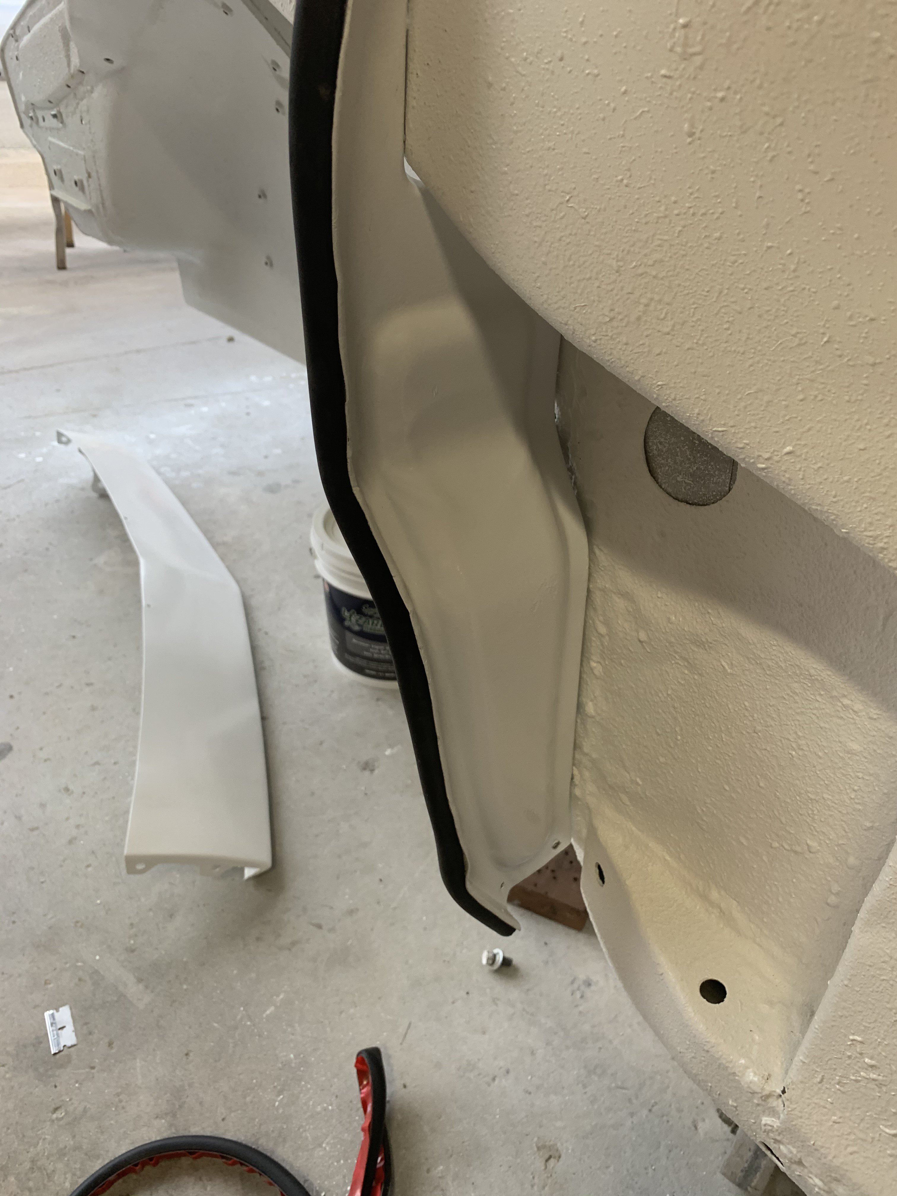
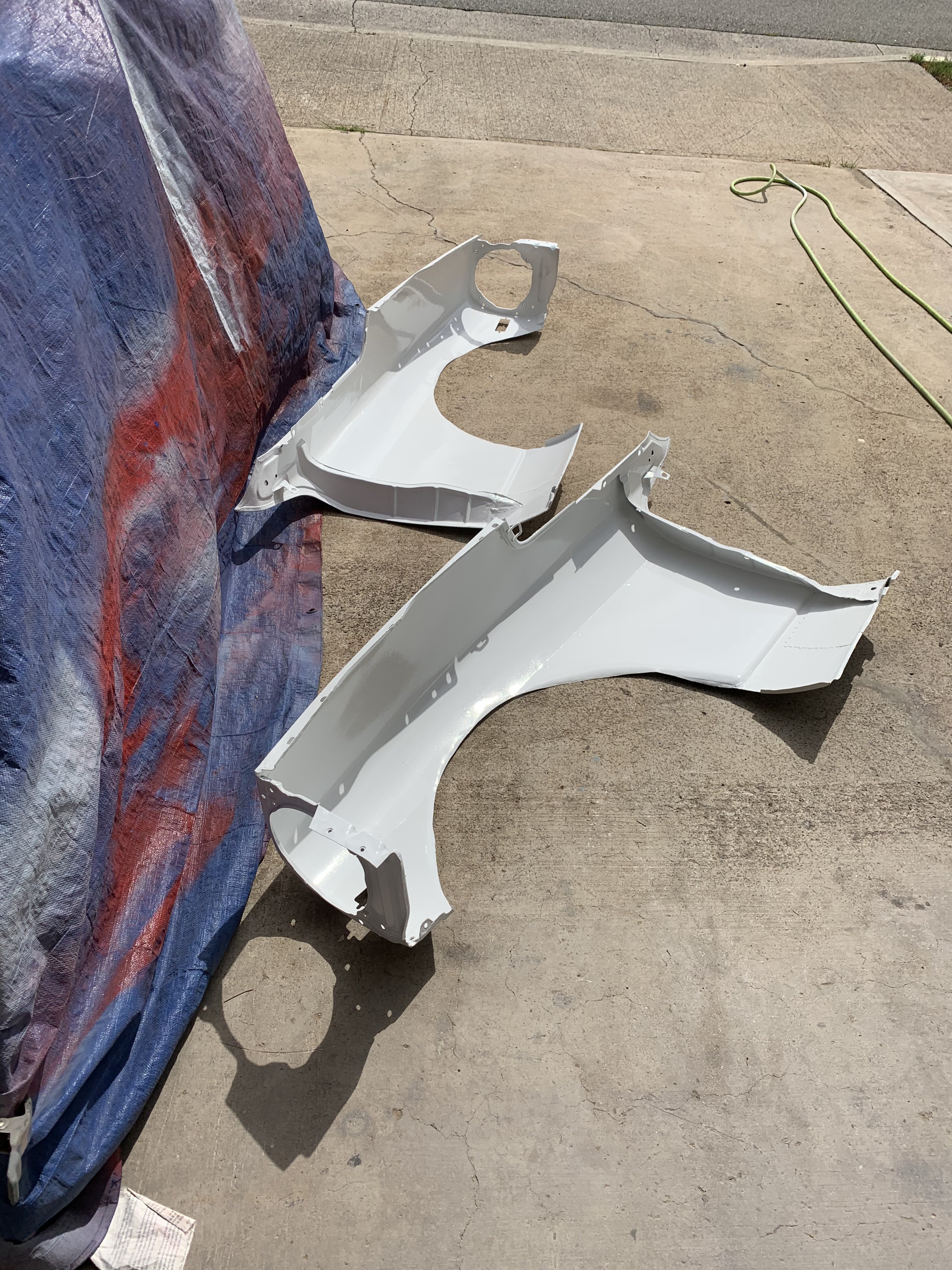
Just returned from vacation in Tokyo. While travelling the rural area, I manage a get a picture{not a good one though} of a Japanese Snap On Tool Truck. I think it is only about 12' long box van. Tiny in US standards. Snap On Tools in Japan sell for double of US prices too. However, when I returned home. there was a Big Surprise for me. The Greddy S30 Rocket Bunny Full Body kit was waiting for me. The shipping box was about 18" x 24" x 8 foot long thick card board. It was packed very well also. These kits are only manufactured when you order it. It took 9 months before I received it. But as the pictures show the quality and workmanship was top notch. The Rocket Bunny Kit consists of one- Front Lower Panel, one Front Bumper, two Front Fenders, two-Rear Fender Flares, one Rear Spoiler and bag of Miscellaneous Mounting bolts/ Fender Gap Inserts. I am including detail pic of the individual fiberglass parts so their quality workmanship can be seen. Front view of parts Rear View of Parts Inside of Front Lower Panel( note-the smooth figerglass layout and finishing sanding of the edges.} Backside of Front Fender Inside of Rear Flares Outside view of Front Lower Panel Note-very detailed with Turn Signal mounting holes. Exterior view- smooth and detailed Inside view 0f Front Bumper Note- Front Bumper Mounting insert Top View-Front Bumper Rear View-Rear Spoiler Front view-Rear Spoiler The real test of a good body kit is its fitment. Those cheap Chinese kits usually require a lot of manhours to make them to look decent. Front bumper and lower front panel Left front Flare Right Front flare Left rear flare(note separate door flare Side view of Rocket Bunny Body kit Front view of Rocket Bunny Kit The Front Flares only require trimming the fender to make it work. The rear flares will require more manhours to fill the gap between the inner and outer quarter panels and the outer flare.
-
Heavy Duty frame rails and connectors
toolman replied to toolman's topic in Gen III & IV Chevy V8Z Tech Board
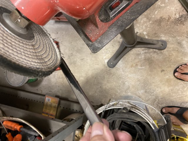
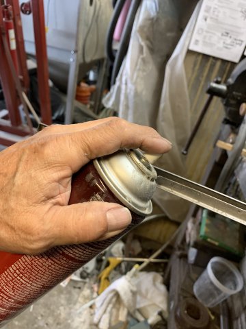
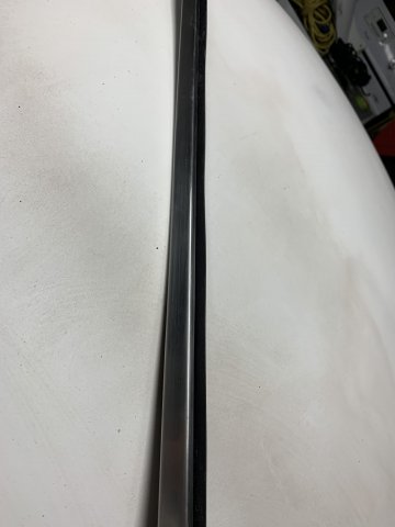
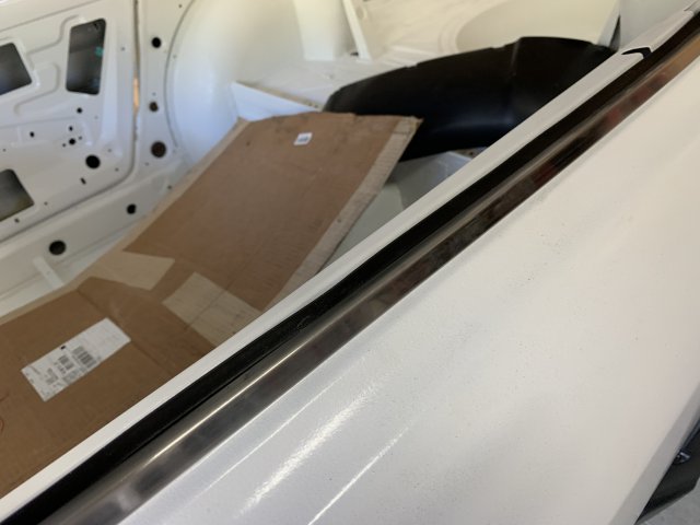
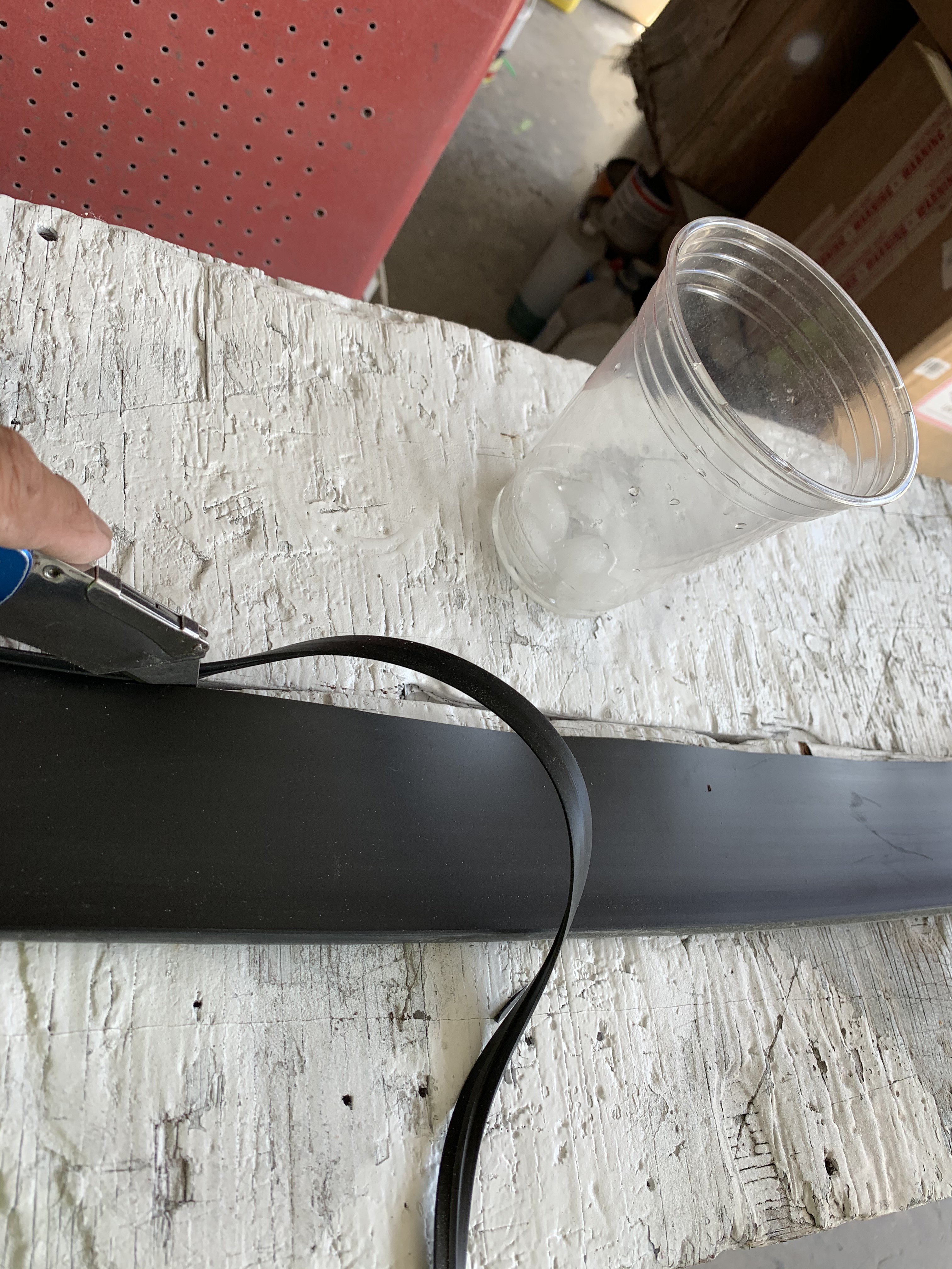
The original door glass molding was in terribly shape. First thing to do was removing the old weather stripping. The old weather stripping is attached using staples. The best way to remove the molding is to twist the weather stripping with pliers to continue to "roll up" the weather stripping. If the stainless has scratches or small dents, repair them first. Then, sand with 400 grit sand paper then slowly progress to 1000 grit. Then, use a cloth buffing wheel prepared with Stainless Steel Polishing Rouge to get it to look like new. I tried using pop rivets to hold the weather stripping on the molding but the rivet head protruded too far inward. Instead, 3M spray adhesive was applied to under the weather tripping and on to the molding surface. After waiting 30 minute for adhesive to dry, the weather stripping was installed on the molding. Cross section view of the weather stripping glued on the molding. polished molding and new weather stripping. Molding installed on door Used Chrysler Christmas Tree clips(from Ebay} to hold lower fender flap.
-
Heavy Duty frame rails and connectors
toolman replied to toolman's topic in Gen III & IV Chevy V8Z Tech Board
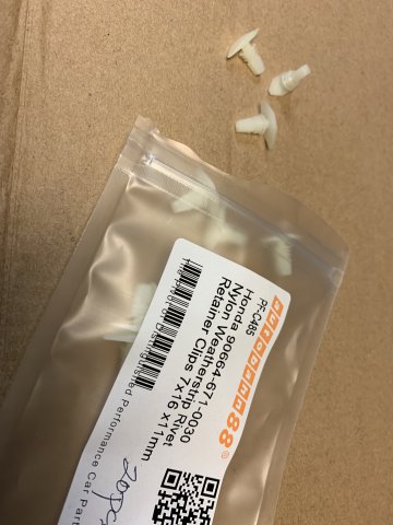
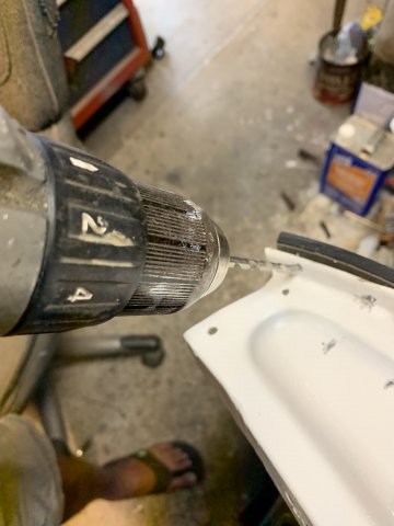
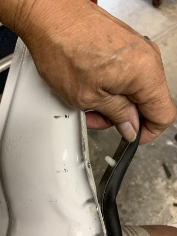
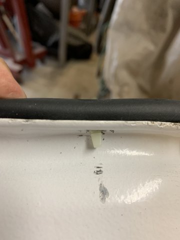
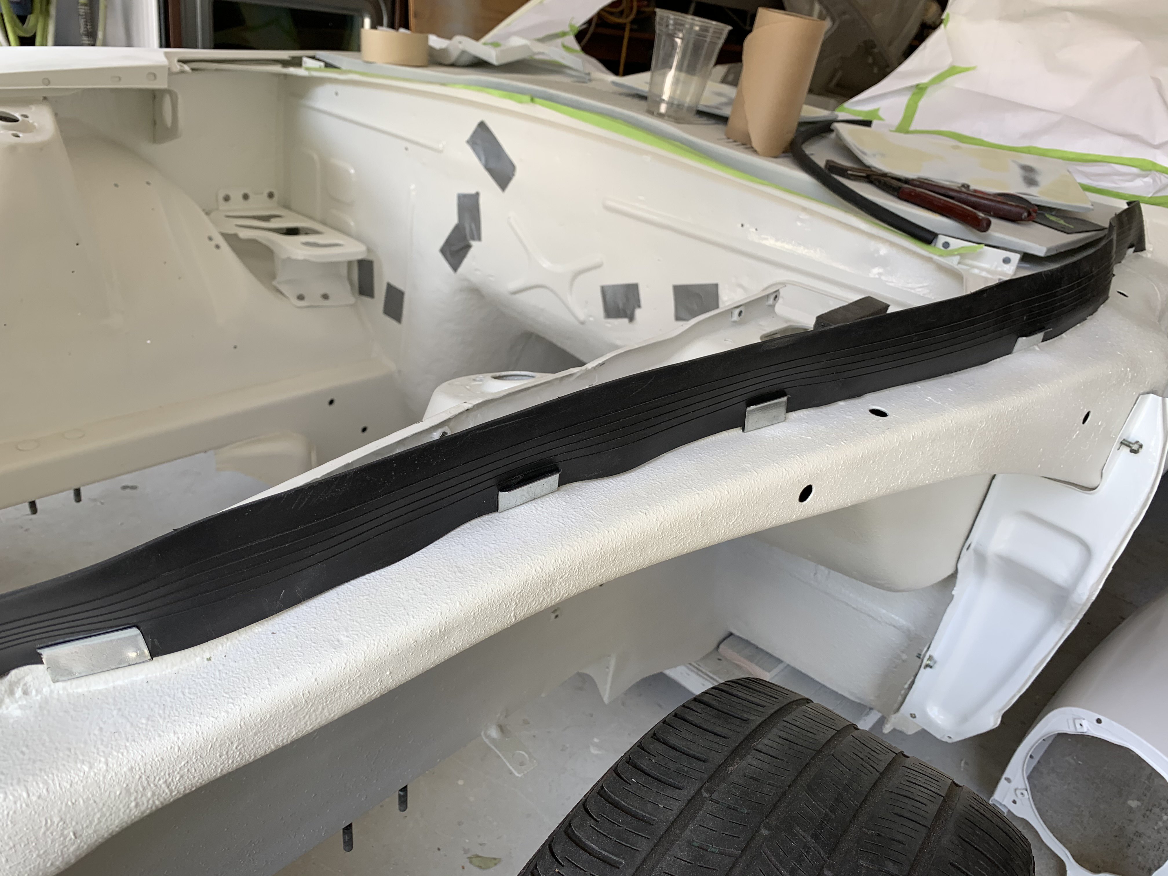
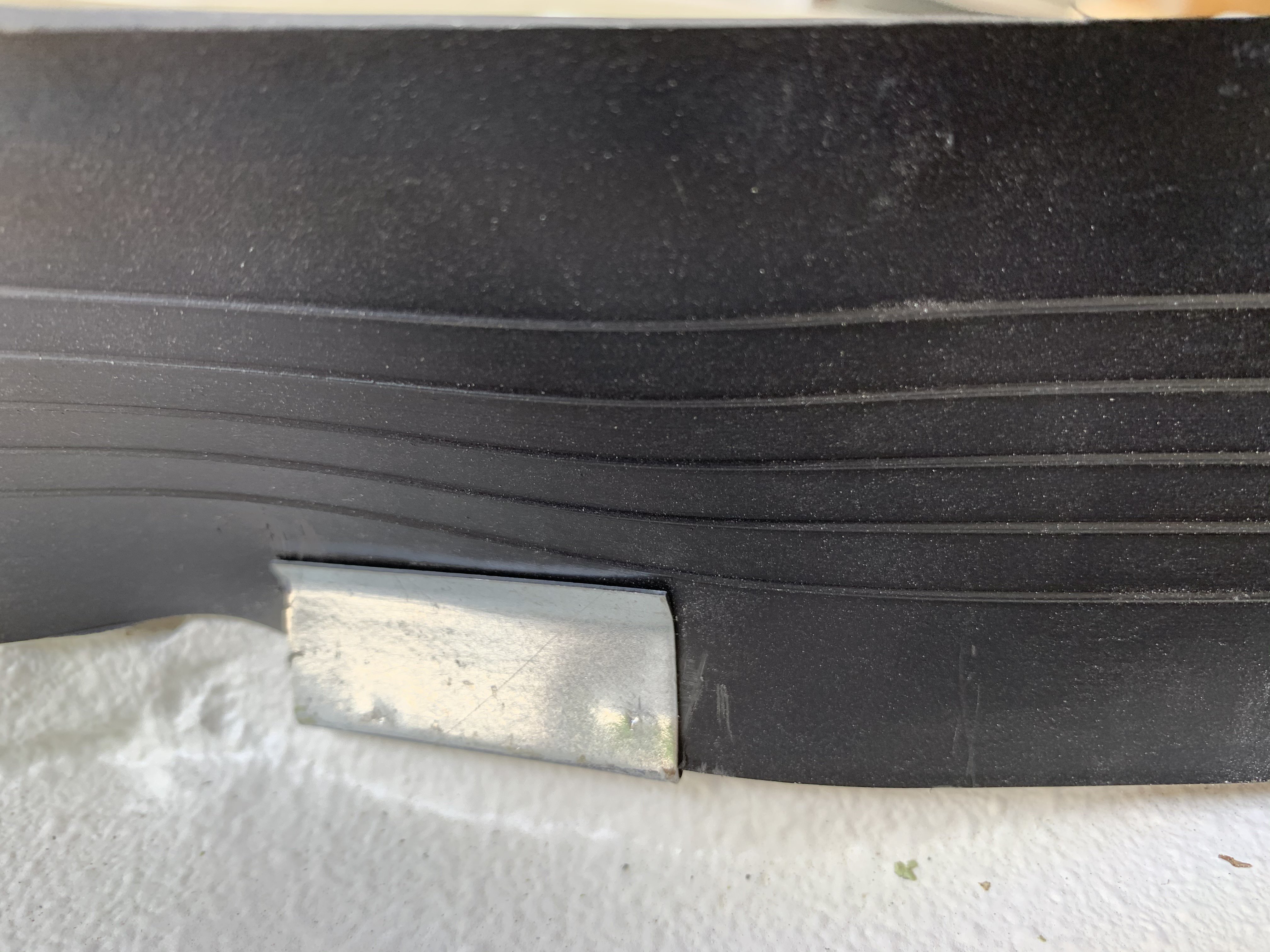
A problem occurred with the weather stripping that was glued to the rear inner fender deflectors. The adhesive was strong enough to hold the weather stripping on. The solution was to use "T" type weather stripping clips( from Chysler) to do the job. Got them from Ebay. 3/16" holes were drilled into the deflector plate. A small scissors was used to create a "Diamond" shaped hole in the weather stripping above the corresponding hole. Twist the "T" clips into the hole In the weather stripping. Push the "T" clip completely into the mounting hole. Pic of the "T" clip fully installed. The Lower fender flap was installed using two "Christmas Tree" type retainers(from Ebay). The retainers replace screws which tend to fall out.
-
PapaSmurf, Try going to CR Laurence website. They are one of the largest glass and glazing product supplier in the USA. Go to their Automotive Section then to Search-type in Sun Roofs. They have all the parts(even the replacement glass). I did not see exact size that you were looking for (33 1/2" X 14") But they had 35" X 15" gaskets so you would have cut 1 1/2" off. That is, if the cross section of the gasket was similar. If it is similar, cut the gasket a little larger( 1/4") so if it shrinks, it would not leak. Also, put the gap of the gasket in the rear of the sunroof to help eliminate wind forcing water in as you drive at high speed. I hope this information helps. Toolman
-
Heavy Duty frame rails and connectors
toolman replied to toolman's topic in Gen III & IV Chevy V8Z Tech Board
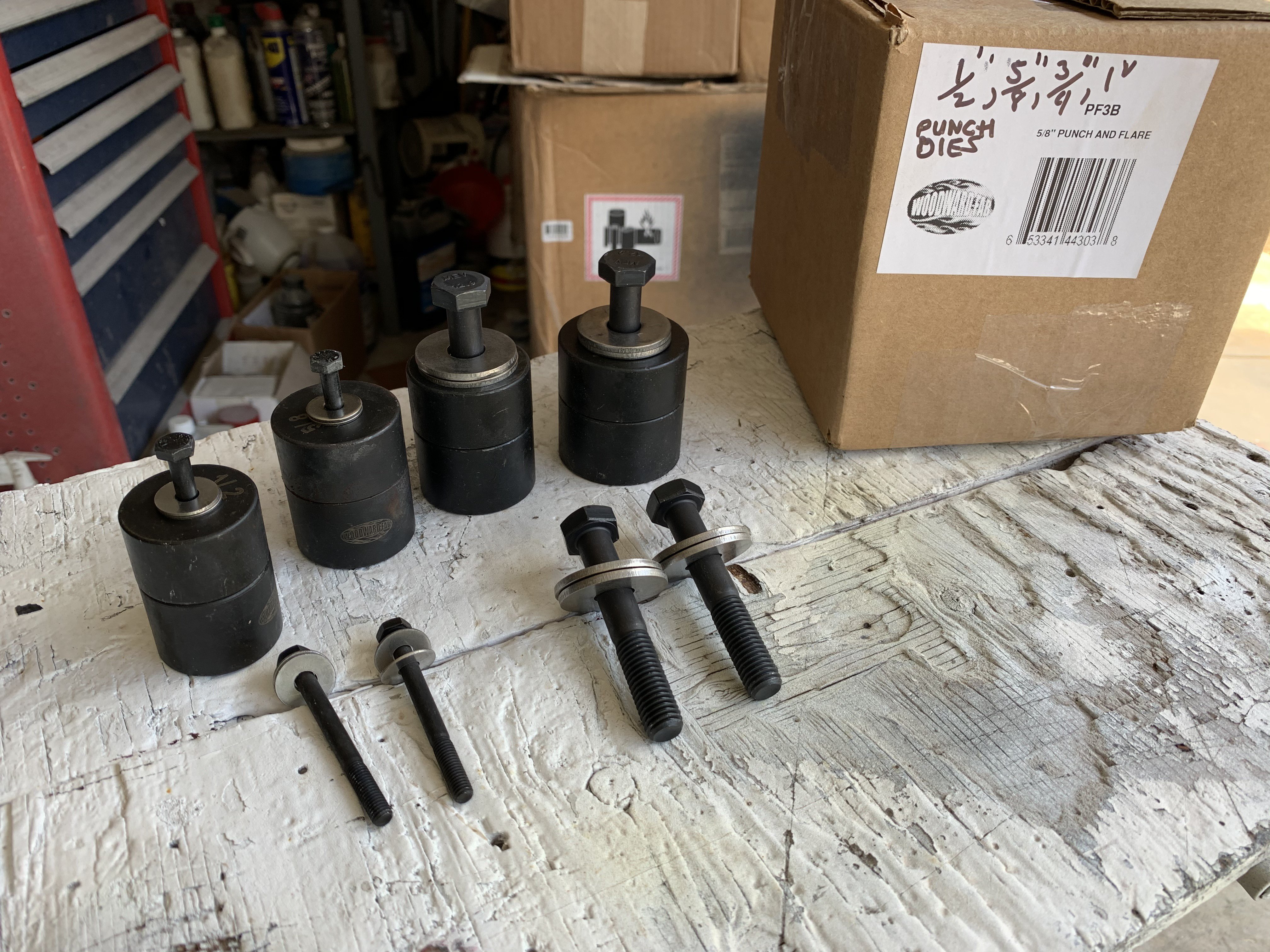
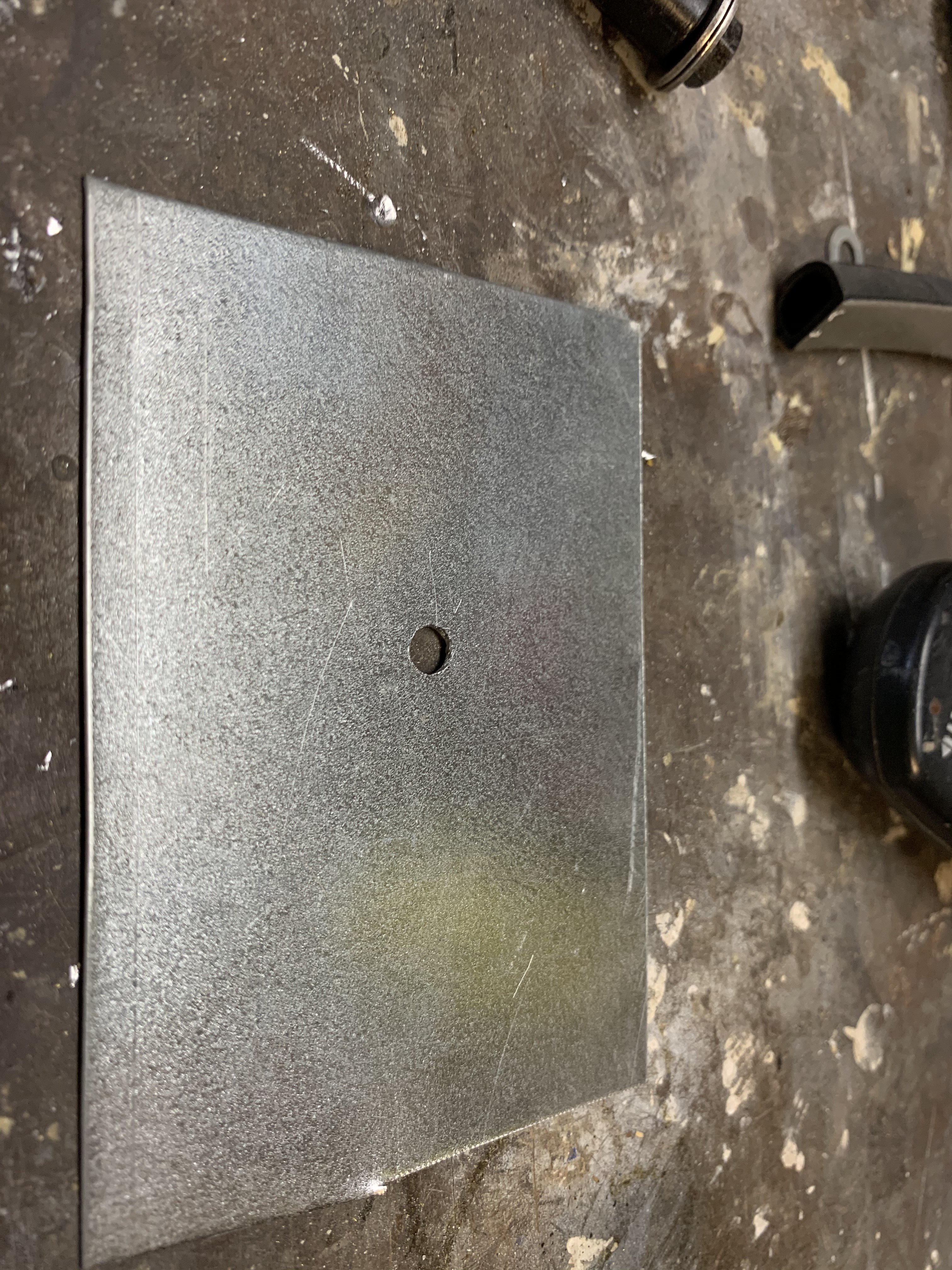
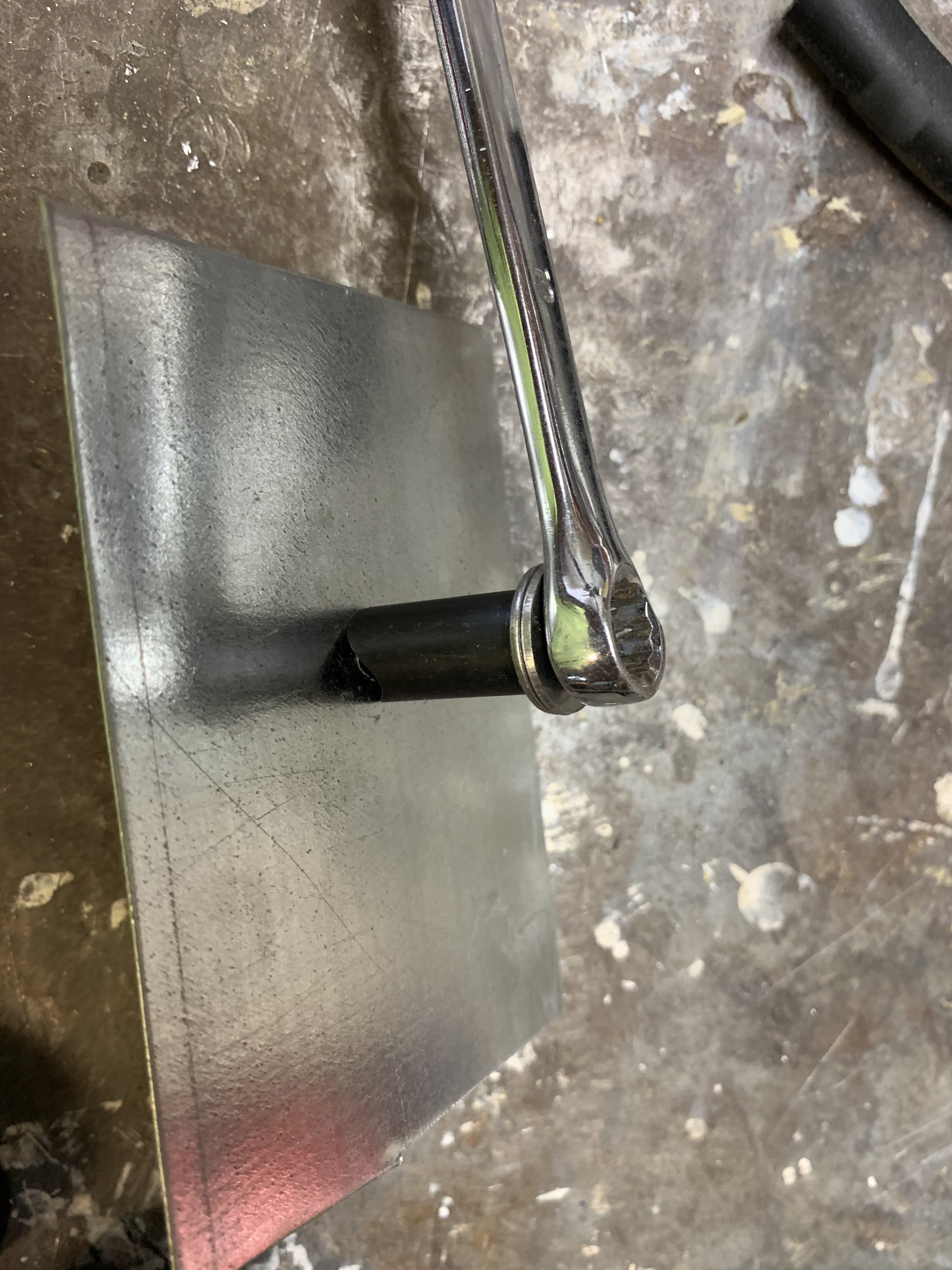
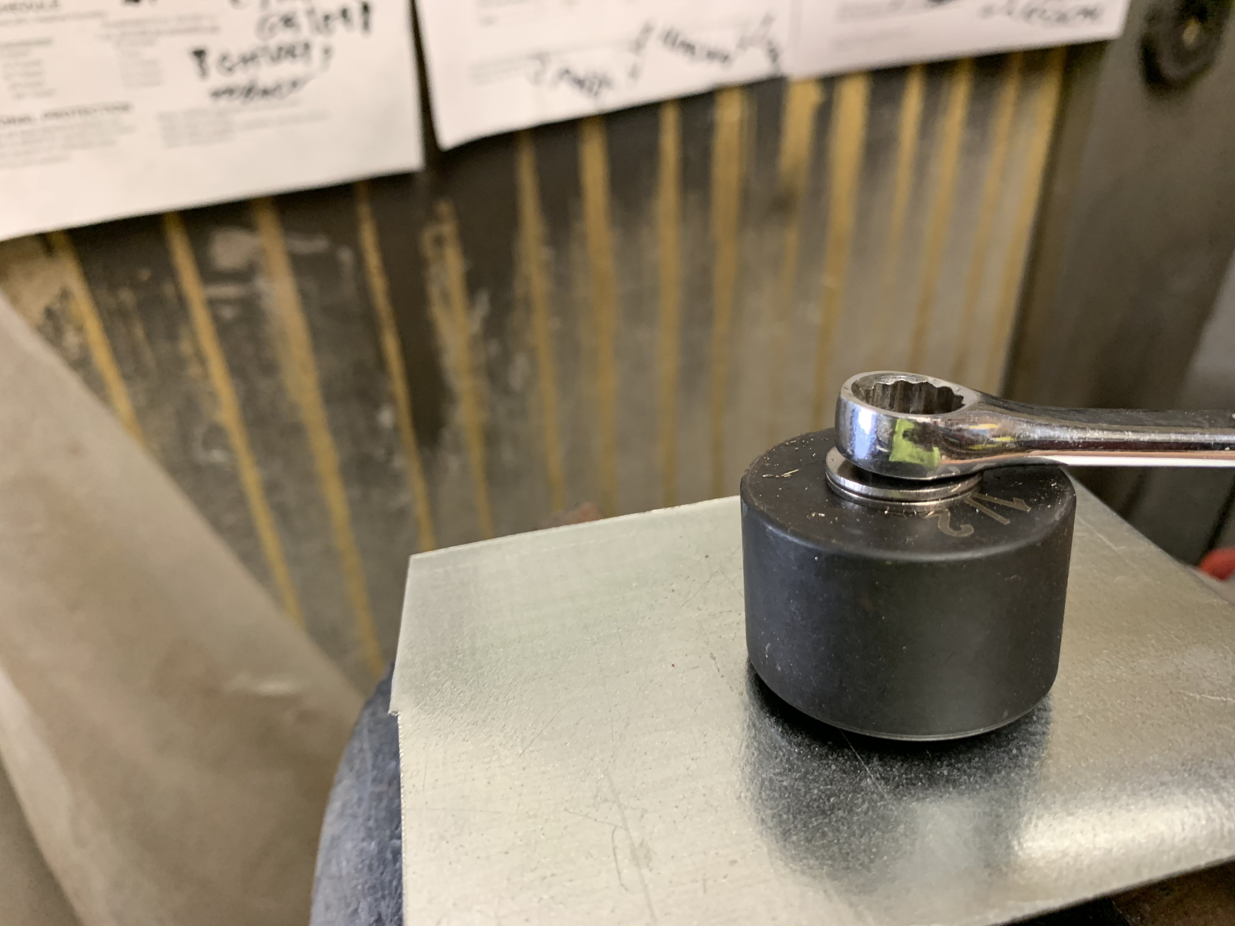
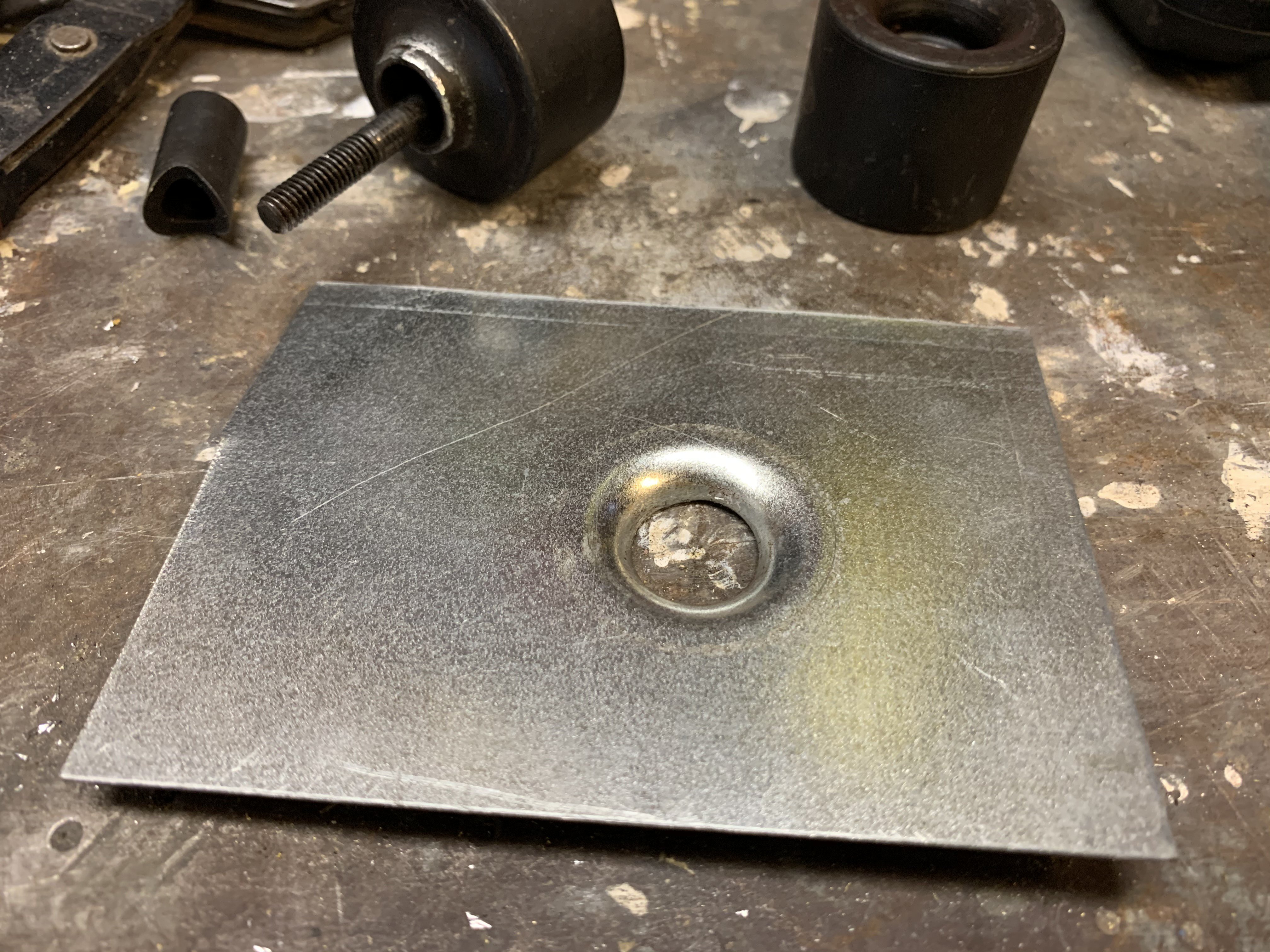
Finishing under the front fenders Decided to make the upper front fender splash deflectors. Bought garage door bottom edge weather stripping from Home Depot for $12. Used a knife to remove both vertical edges to end up with a flat rubber strip. I bent strips of 2" wide sheet metal to create a "S" shaped clip to hold the deflector on the fender support. As I was making the clips, I could adjust the holding tension of the clips by adjusting their gaps. Fender upper side deflector installed. Closeup view of clips Note- The clips edges are bent up slightly to prevent sharp edge from cutting the rubber deflector. I ordered a set of Dimple Dies consisting of sizes from 1/2", 5/8", 3/4" and 1". Using these dies make flat sheet metal a lot stronger and looks "real cool" too. The 240z uses this type of metal forming on its inside rocker panels ,strut supports,etc. First, thing to do, is drill a pilot hole in the sheet metal. In this case, the 1/2" Dimple die requires 5/16" pilot hole. Next, assemble the Cutter blade and bottom die with the 10MM head bolt. As you tighten the bolt, the Cutter blade also turns and cuts a hole into the sheet metal. Continue to tighten the bolt until the Cutter cuts through the sheet metal. Once, the 1/2" hole is made, you reassemble the forming die with the bottom die. Tighten down the Forming Die until it is flush with the surface of the sheet metal. Disassemble the tool and inspect the Dimple Form. If it's not formed enough, reassemble the die and tighten it down more. Bottom View Side View of the finished !/2" Dimple. I will probably use the Dimple Dies to create some support brackets in the interior and maybe construct a Triangular Engine Compartment Support with them.
-
Heavy Duty frame rails and connectors
toolman replied to toolman's topic in Gen III & IV Chevy V8Z Tech Board
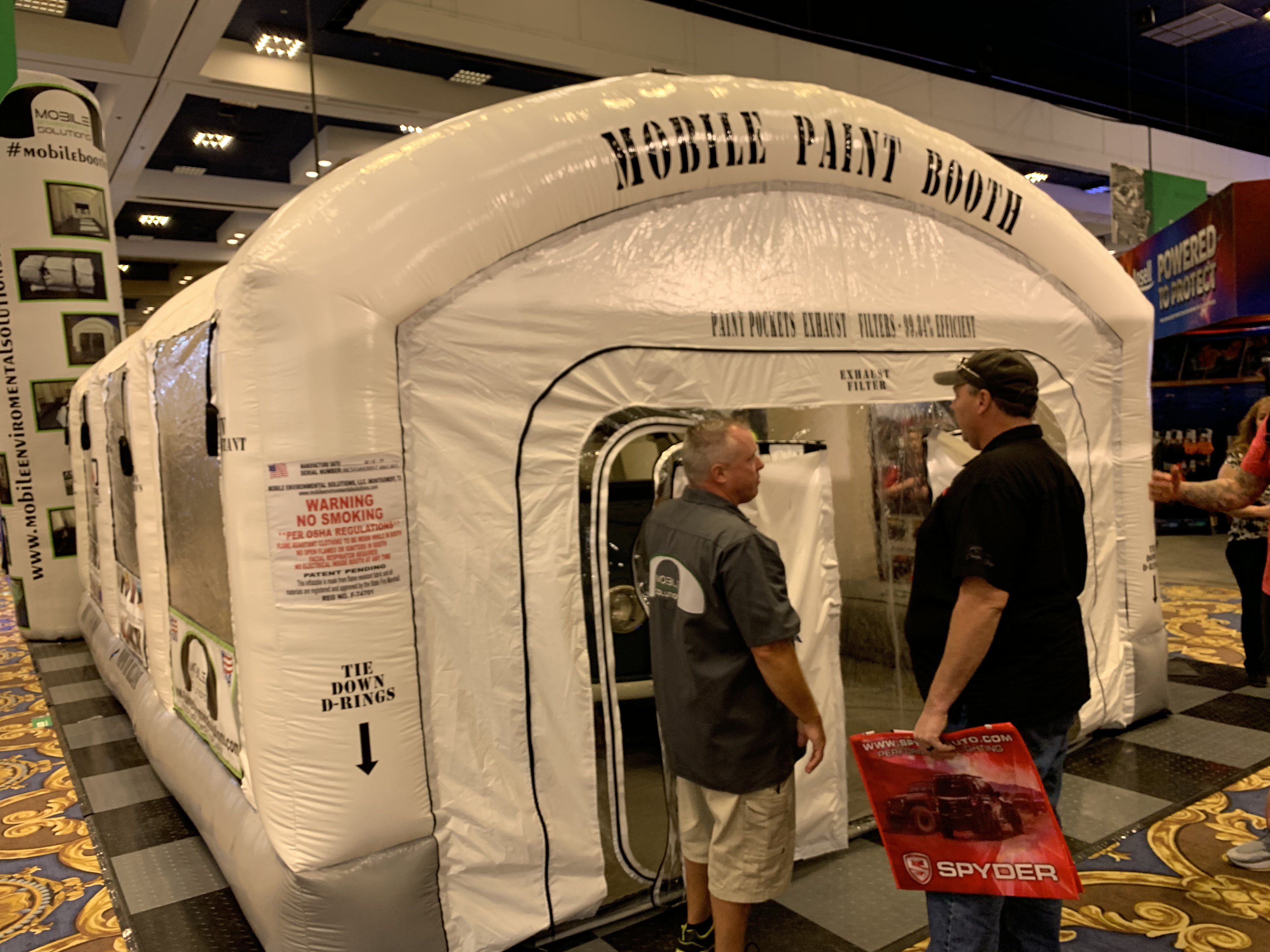
Ebay has a lot of portable China Spray booths that run from $1000 to $2000. Most are a little more than inflatable bounce things. The one at the SEMA is manufactured in Texas by Mobile Environmental Solutions. Single booth 23' x15' was $9995.00 and twin booth 23' x 48' was $19995. They seem to be made of material similar to those auto paint shop curtains that divide up shop areas. According to them, the booth is made of materials that pass NFPA (National Fire Protection Association)701 test methods 1 &2. TV's Garage Squad show is shown using their booths. But I would check with your local fire department first before purchasing one. -
Heavy Duty frame rails and connectors
toolman replied to toolman's topic in Gen III & IV Chevy V8Z Tech Board
That was the price that they quoted me. The major problems with this portable spray booth is it is made out plastic and it does not have a fire suppression system. Most local fire departments would not allow such spray booths to be used. If some one was caught inside in one that caught fire, they would be trapped under a collapsing structure. -
Heavy Duty frame rails and connectors
toolman replied to toolman's topic in Gen III & IV Chevy V8Z Tech Board
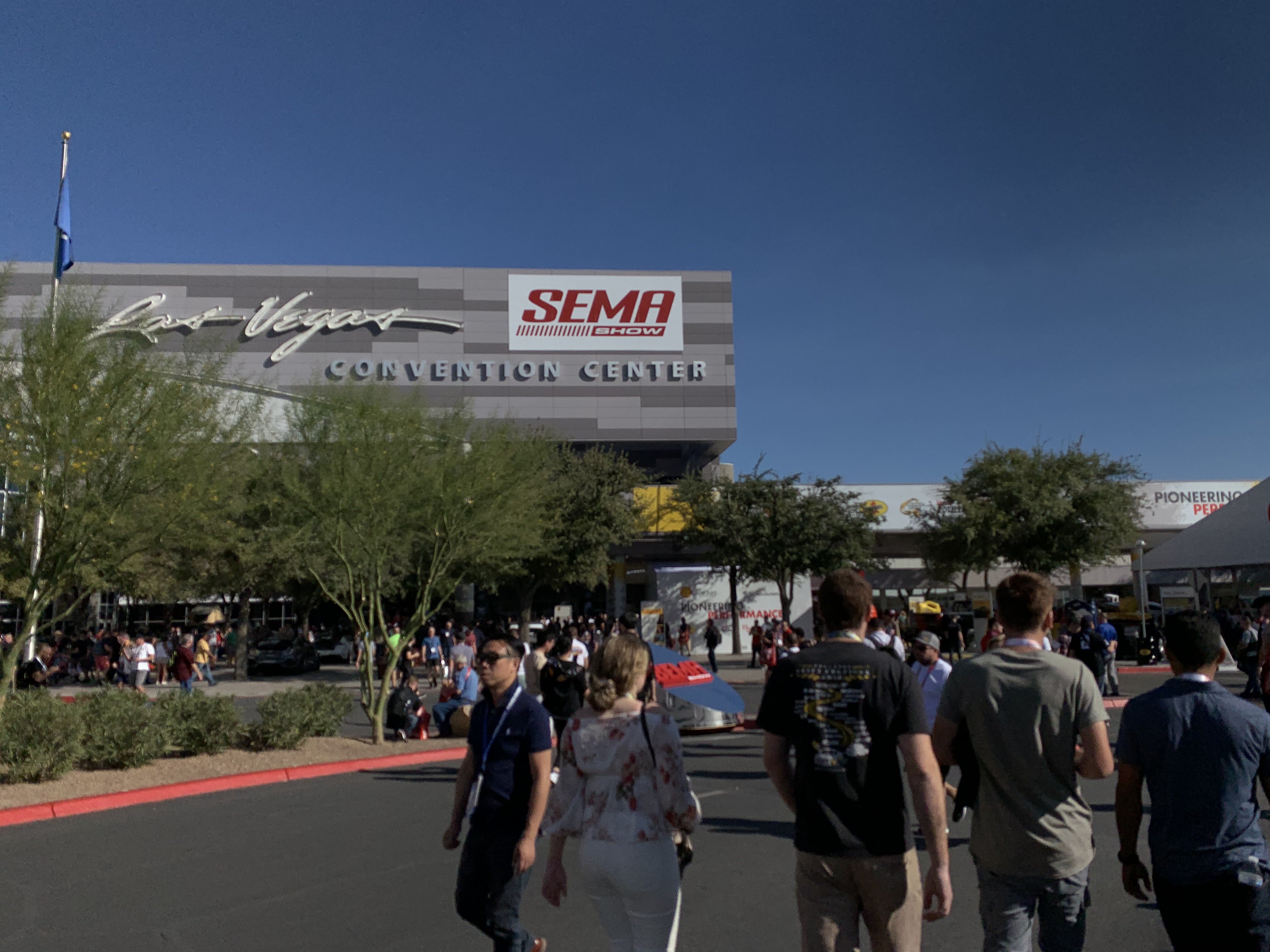
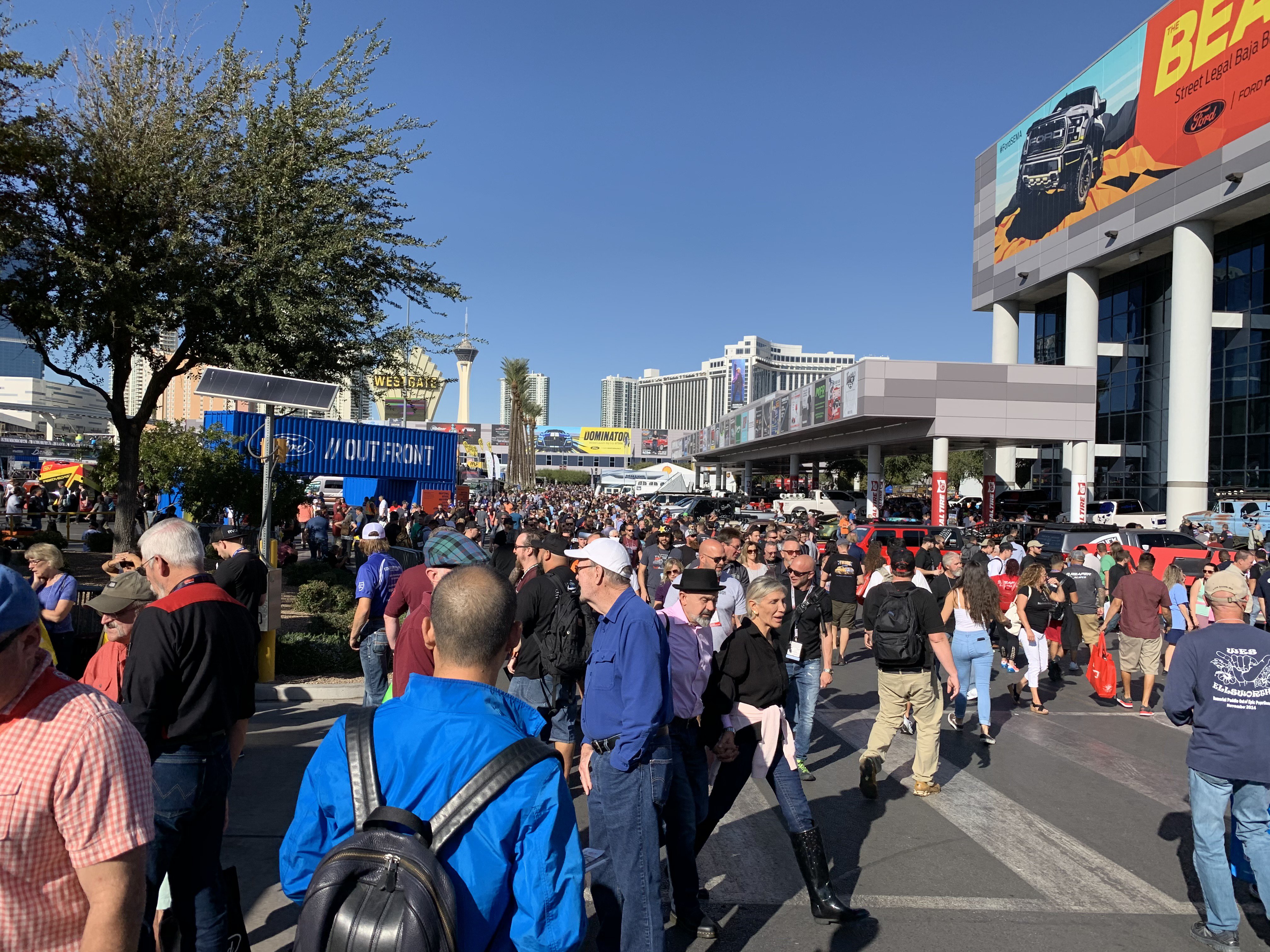
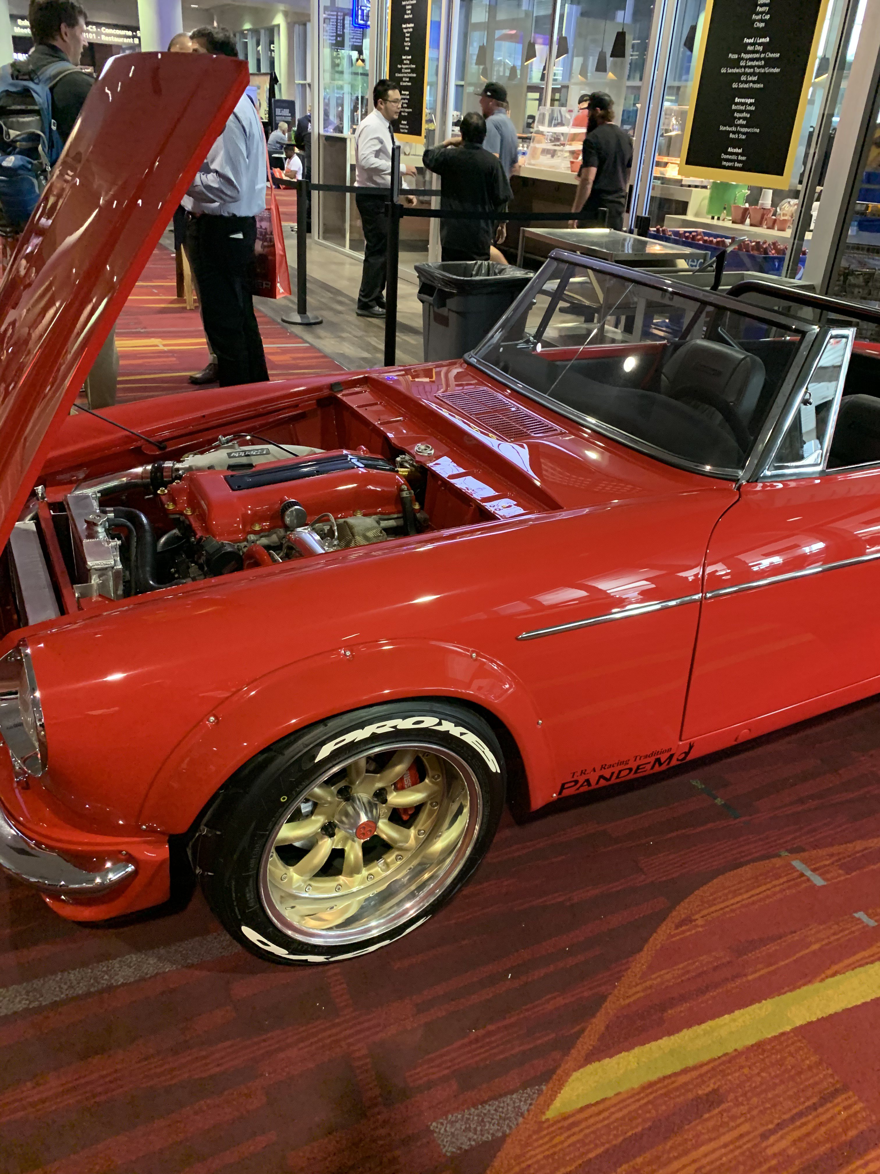
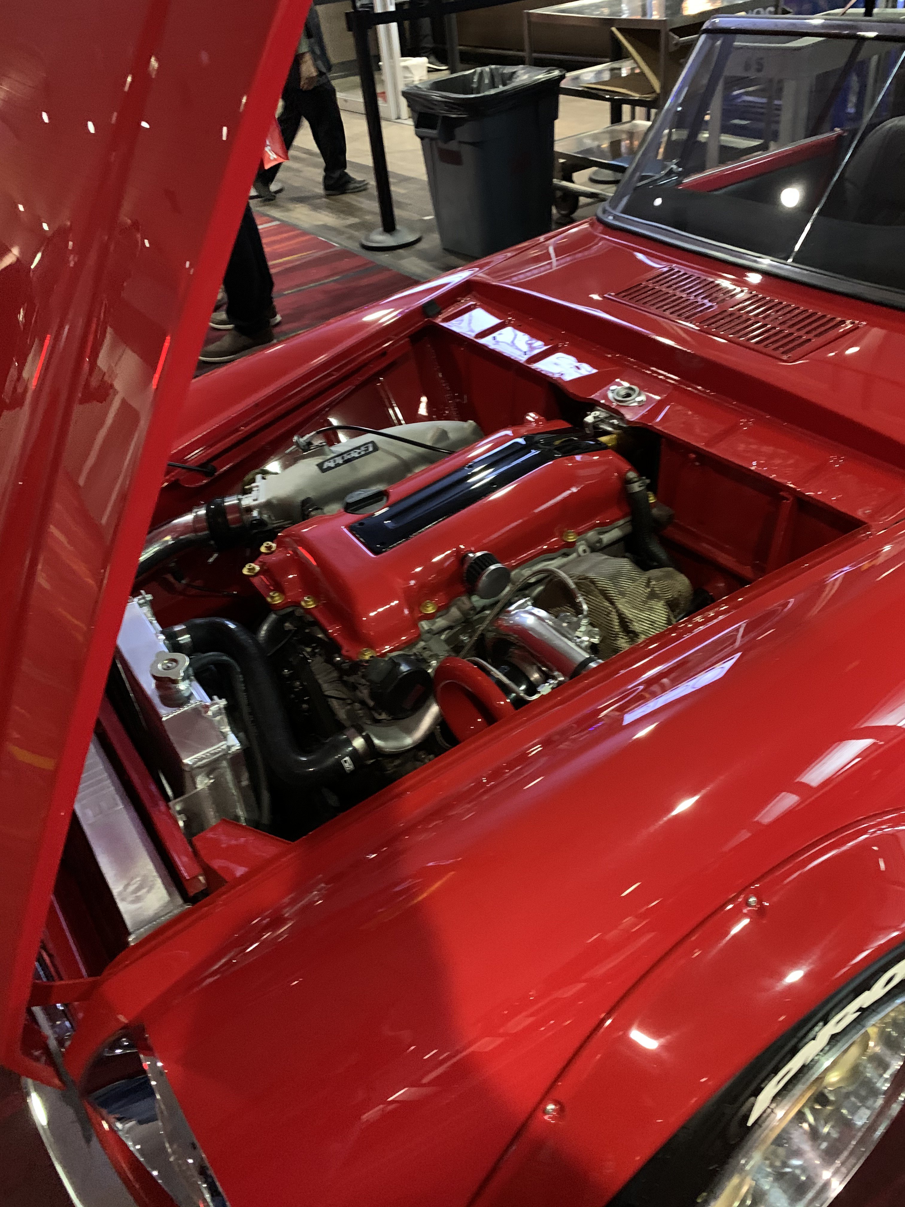
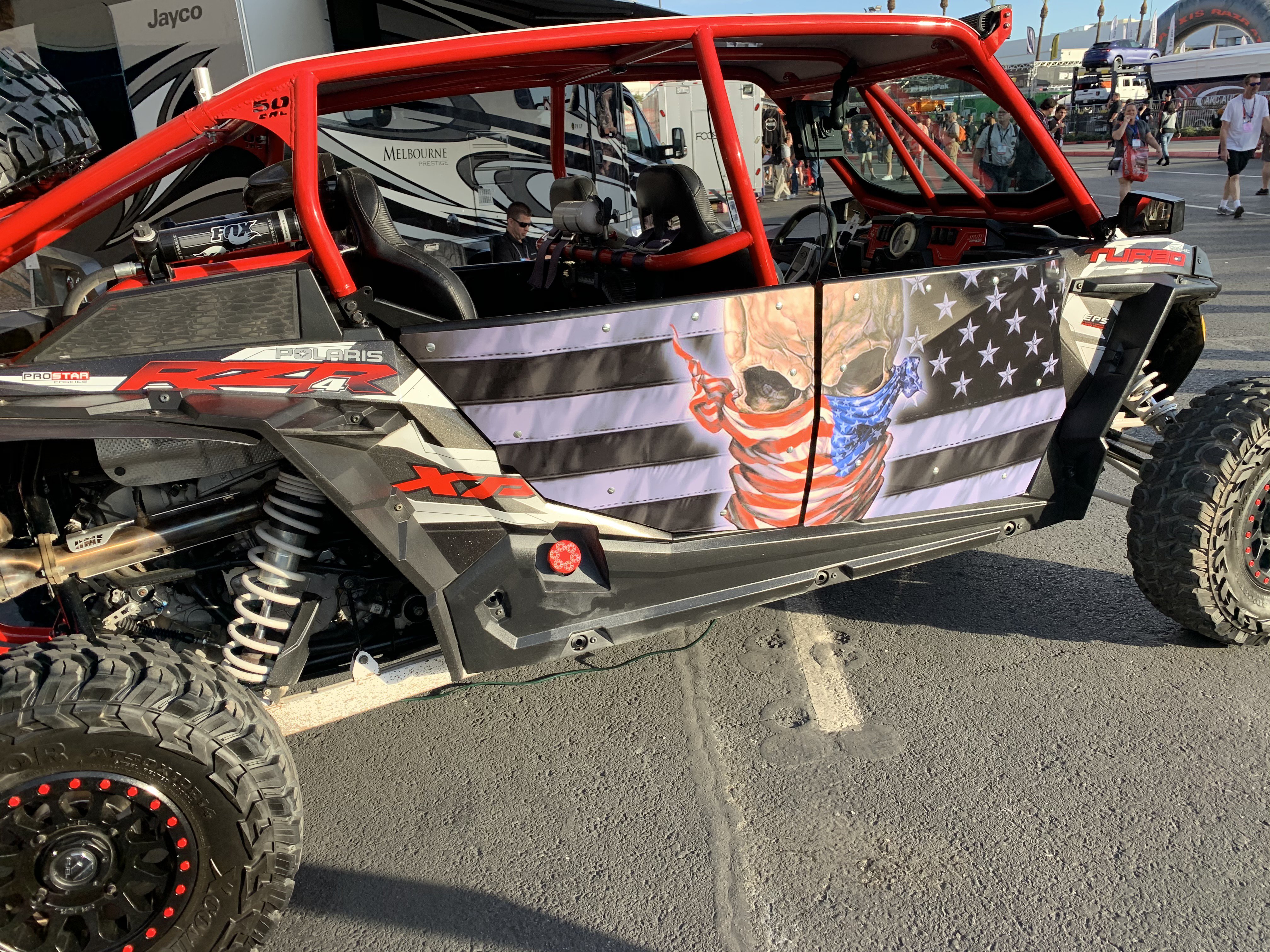
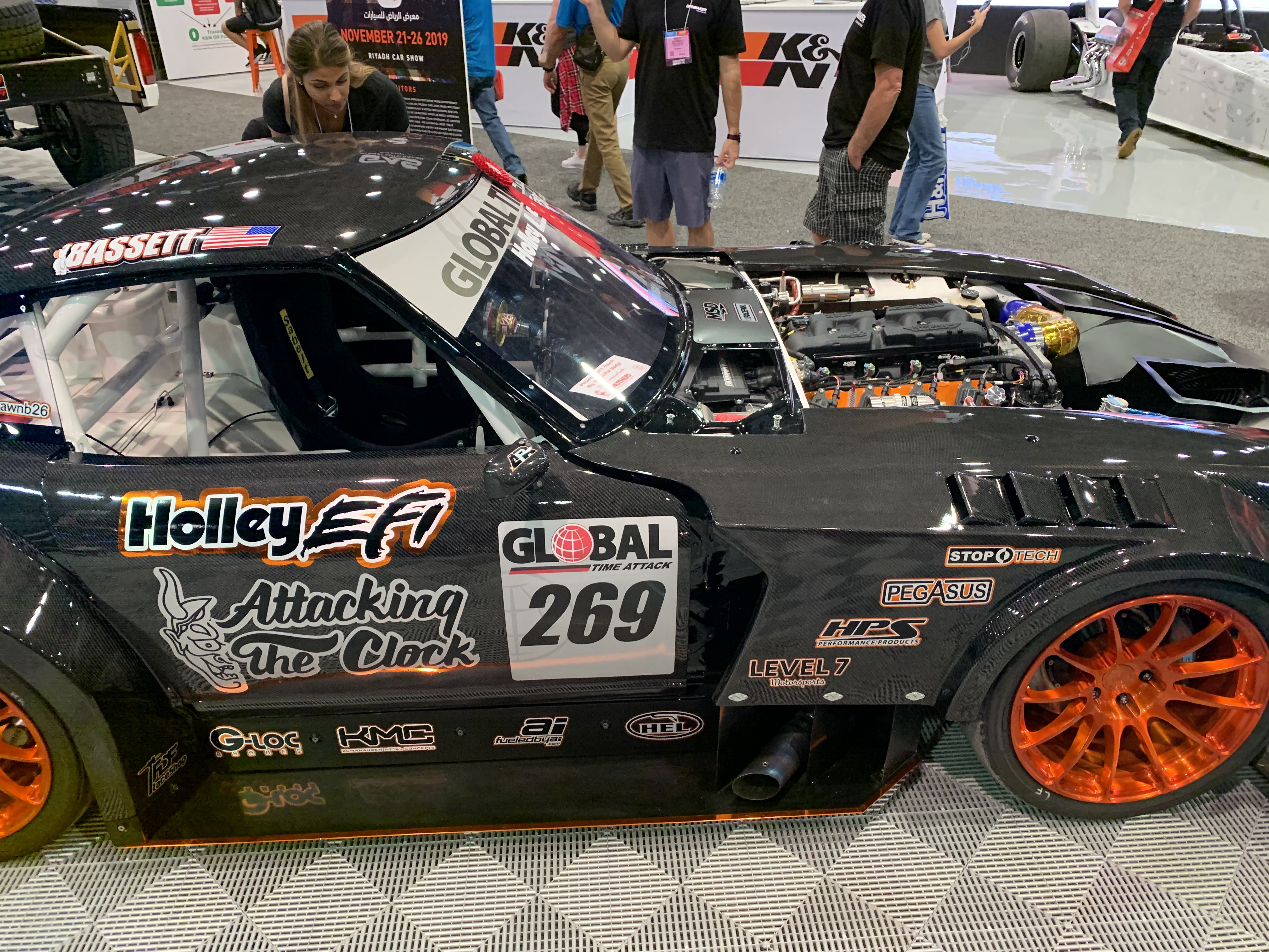
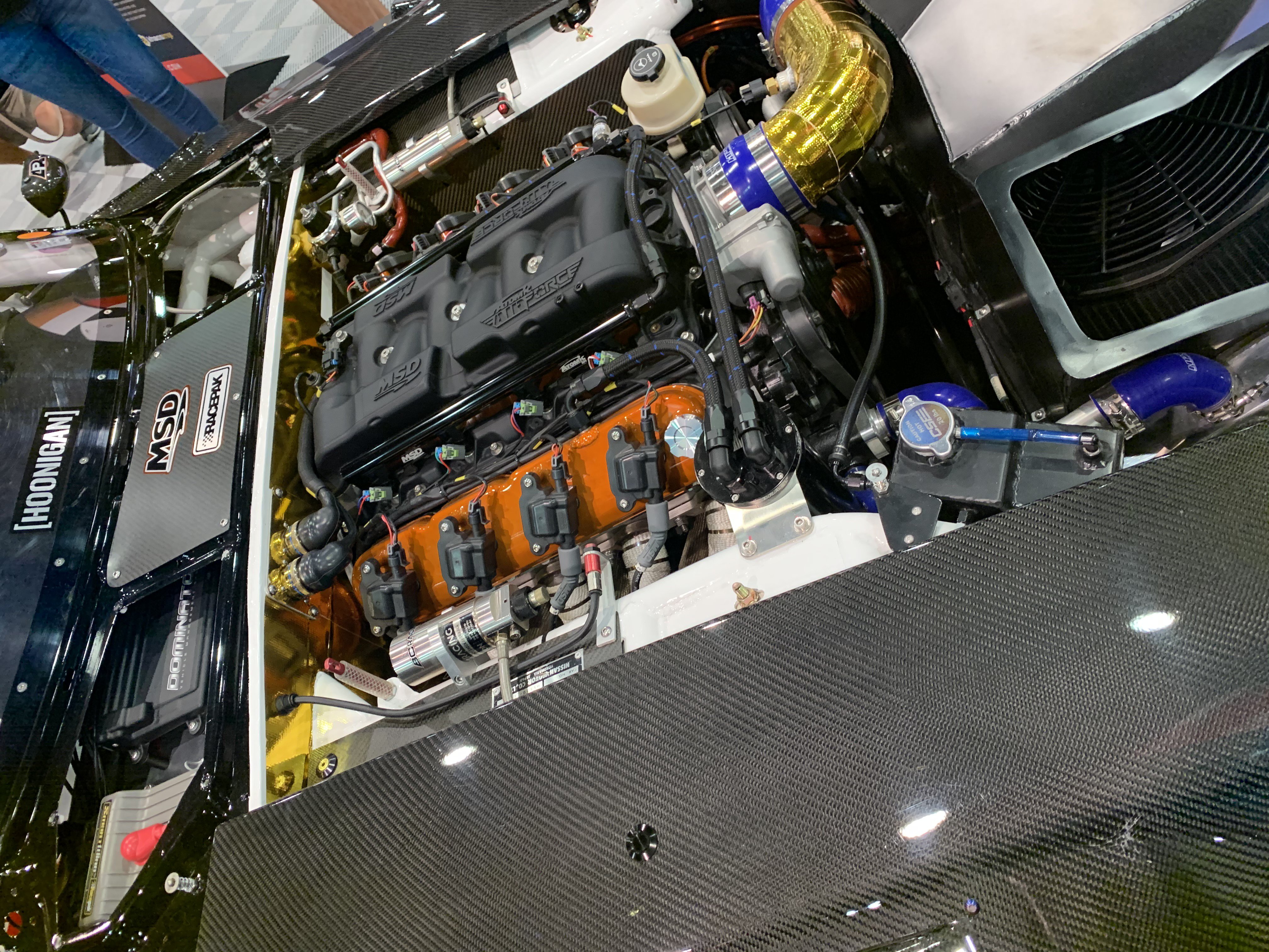
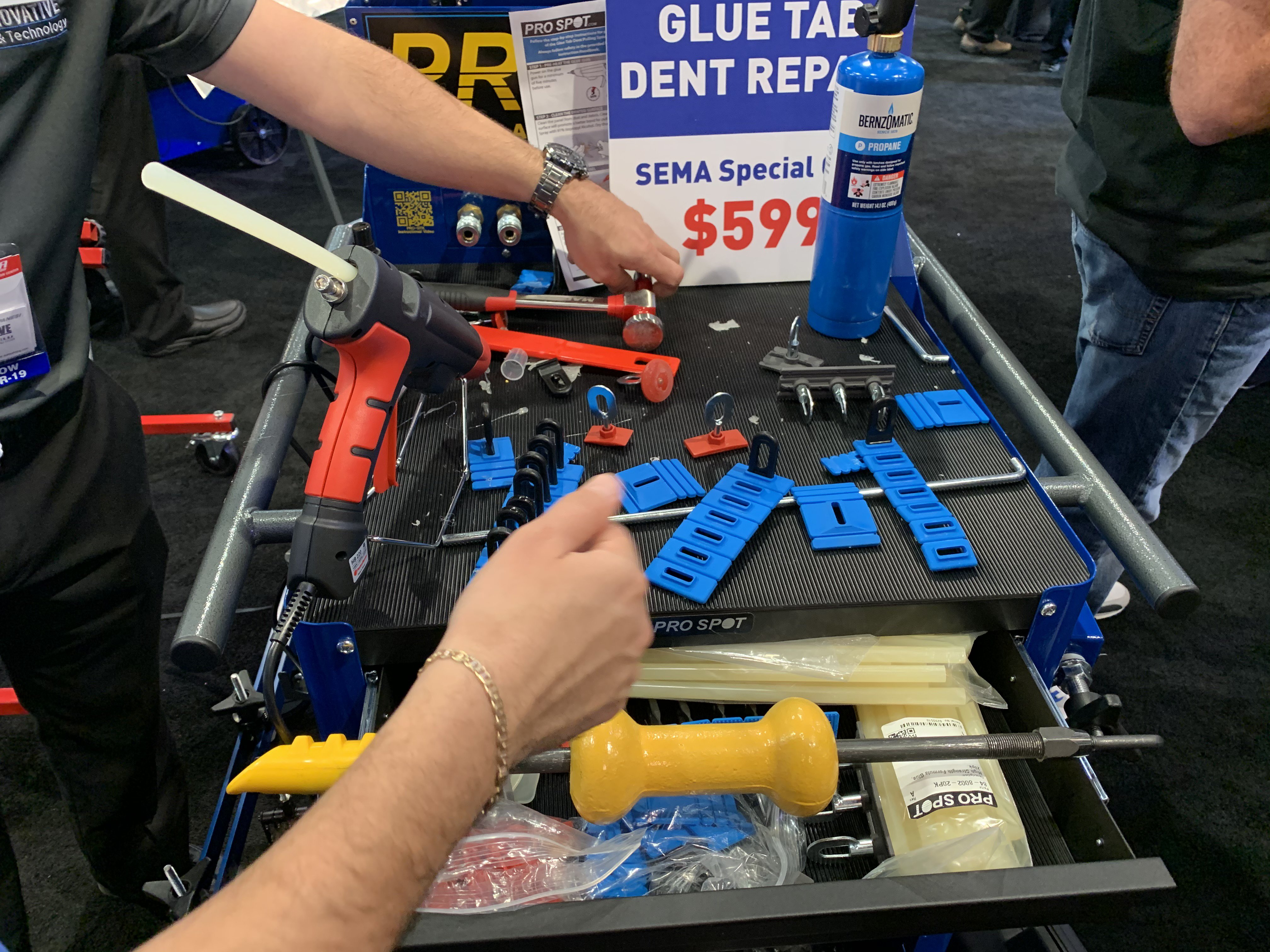
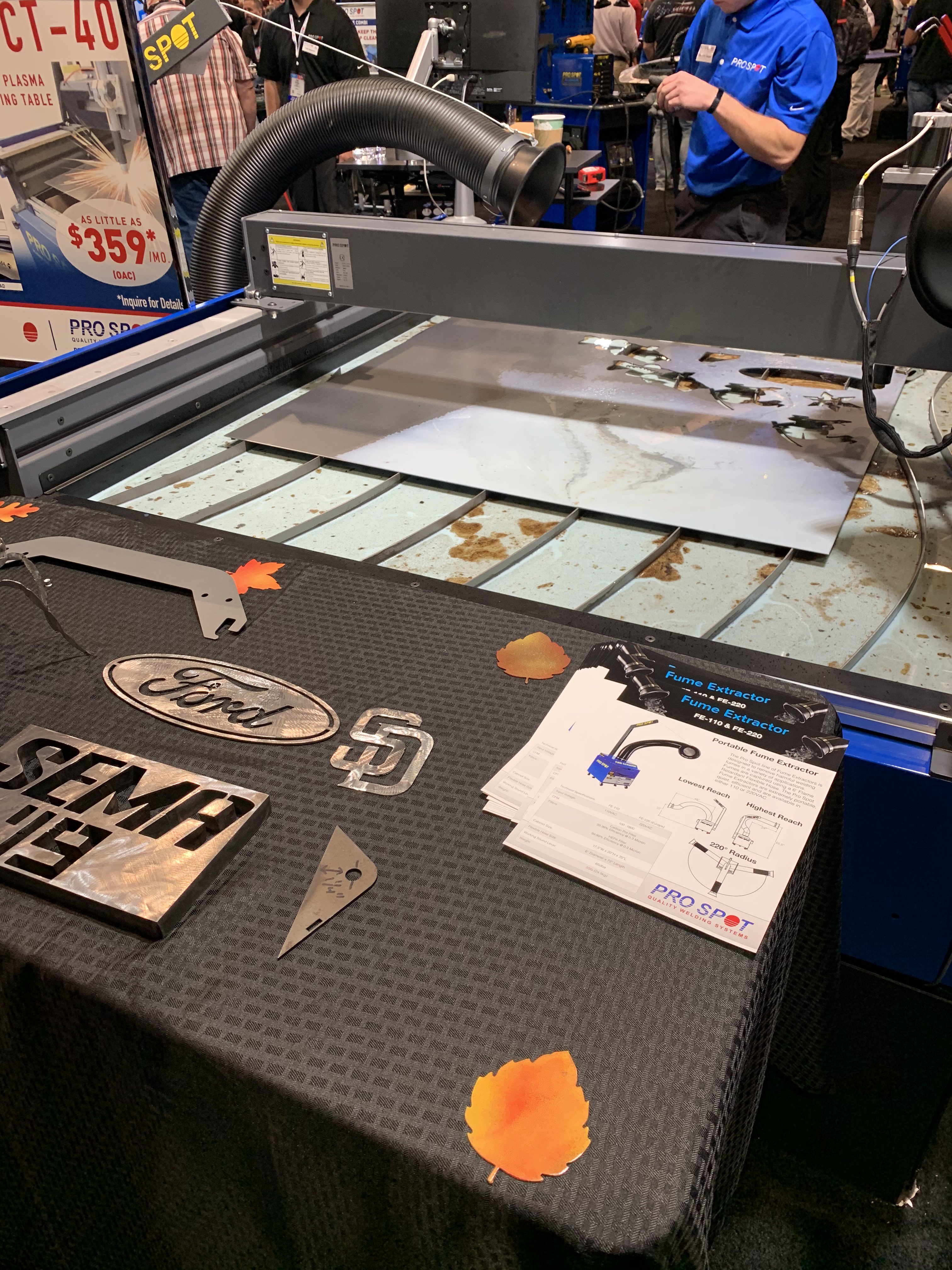
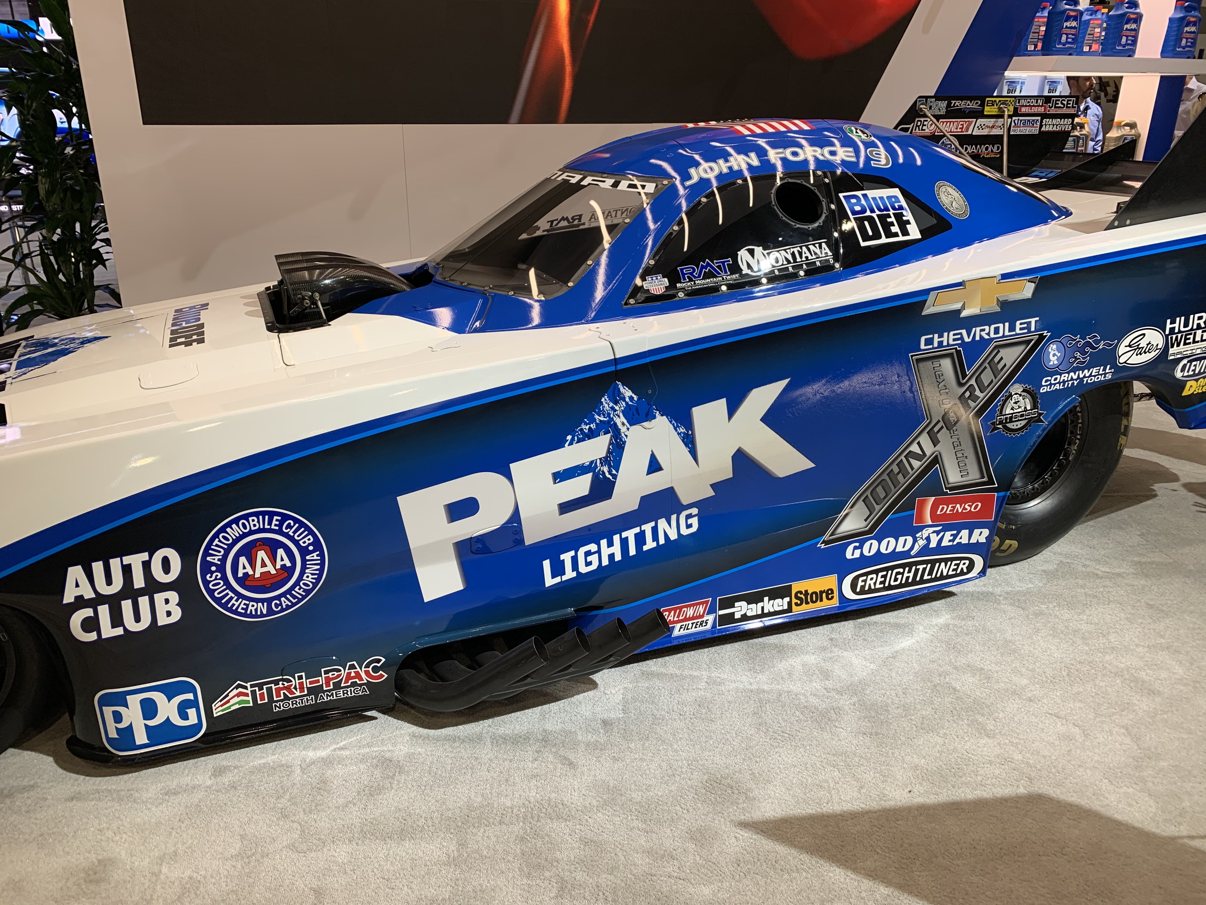
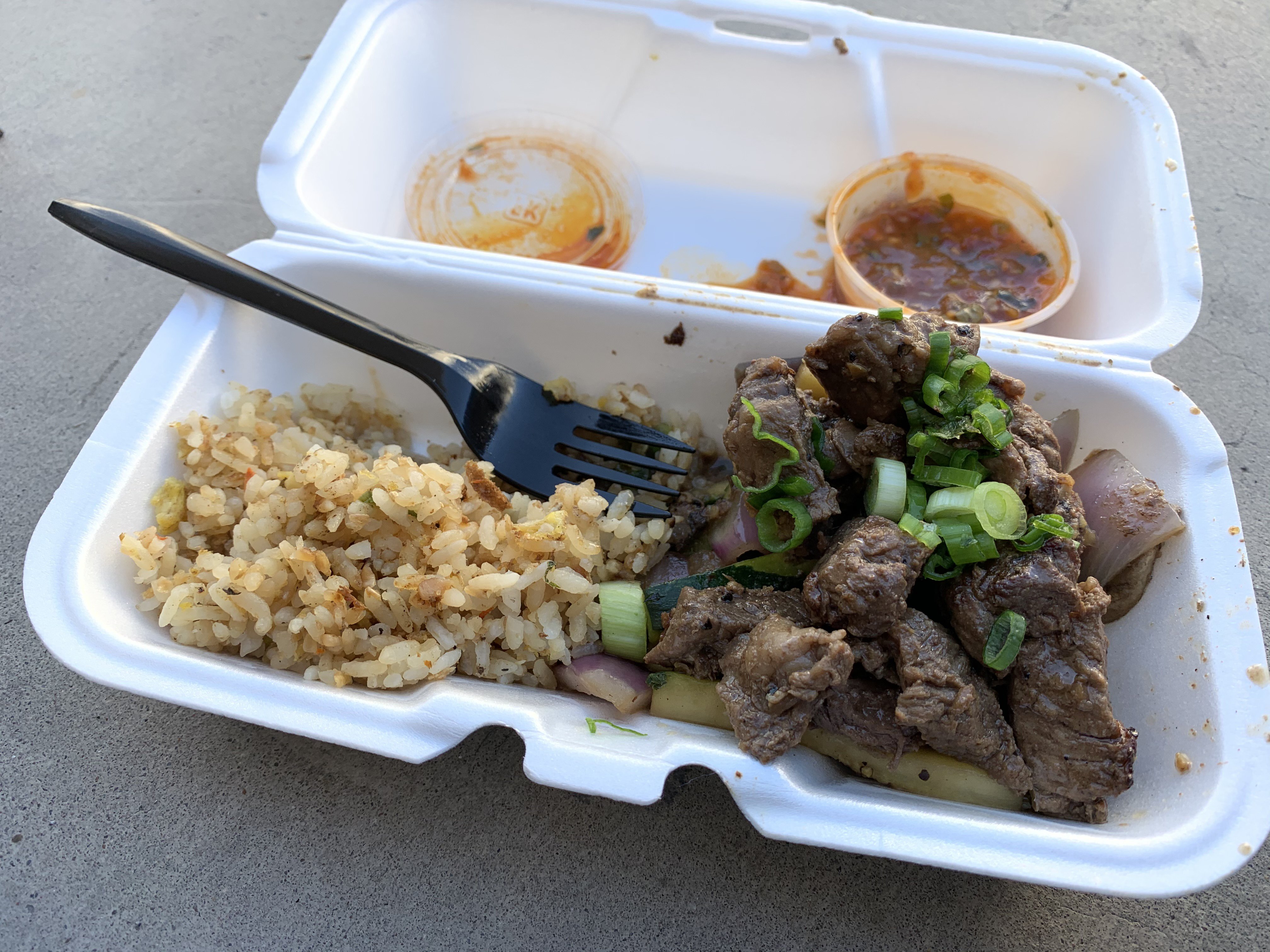
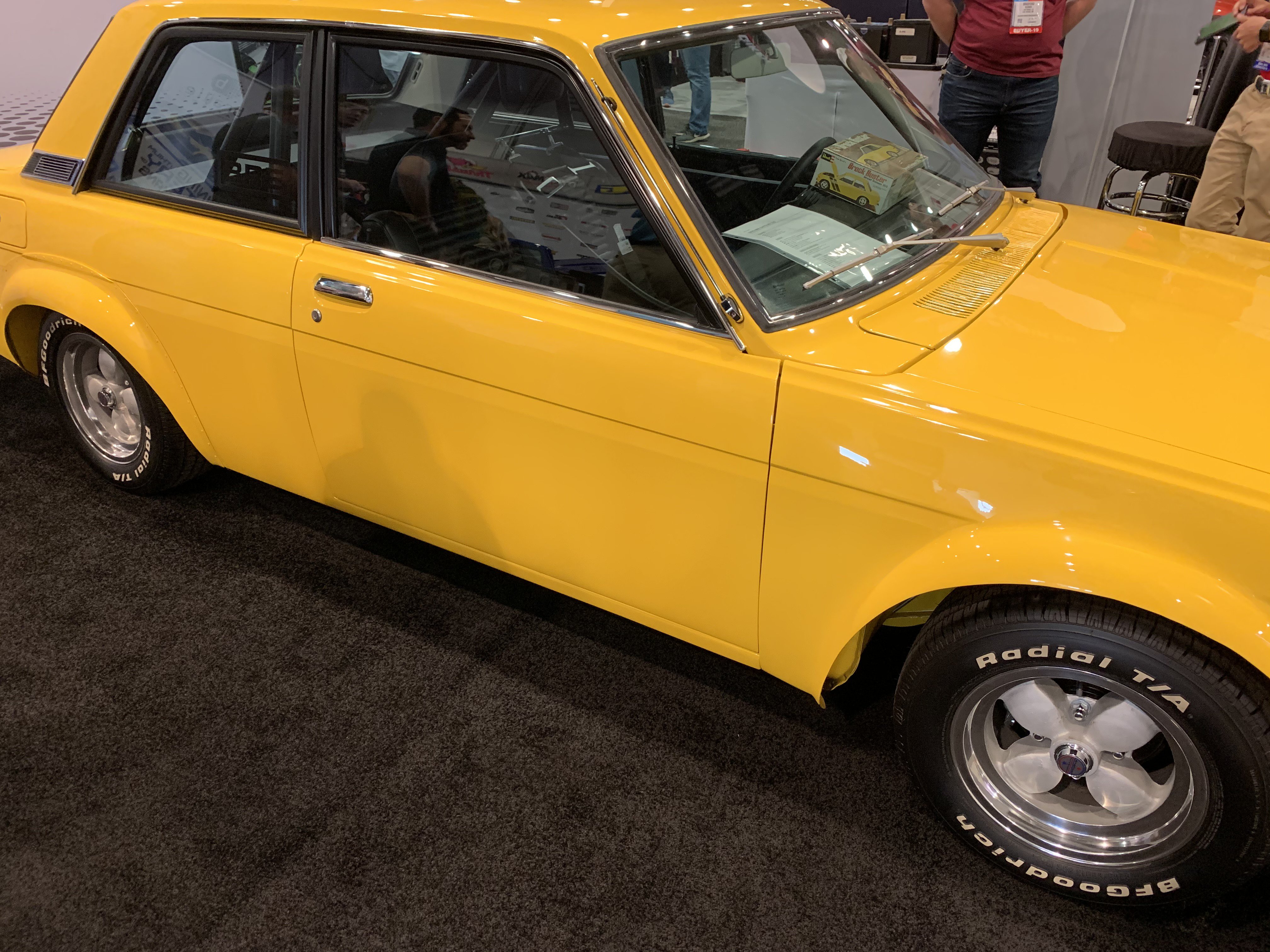
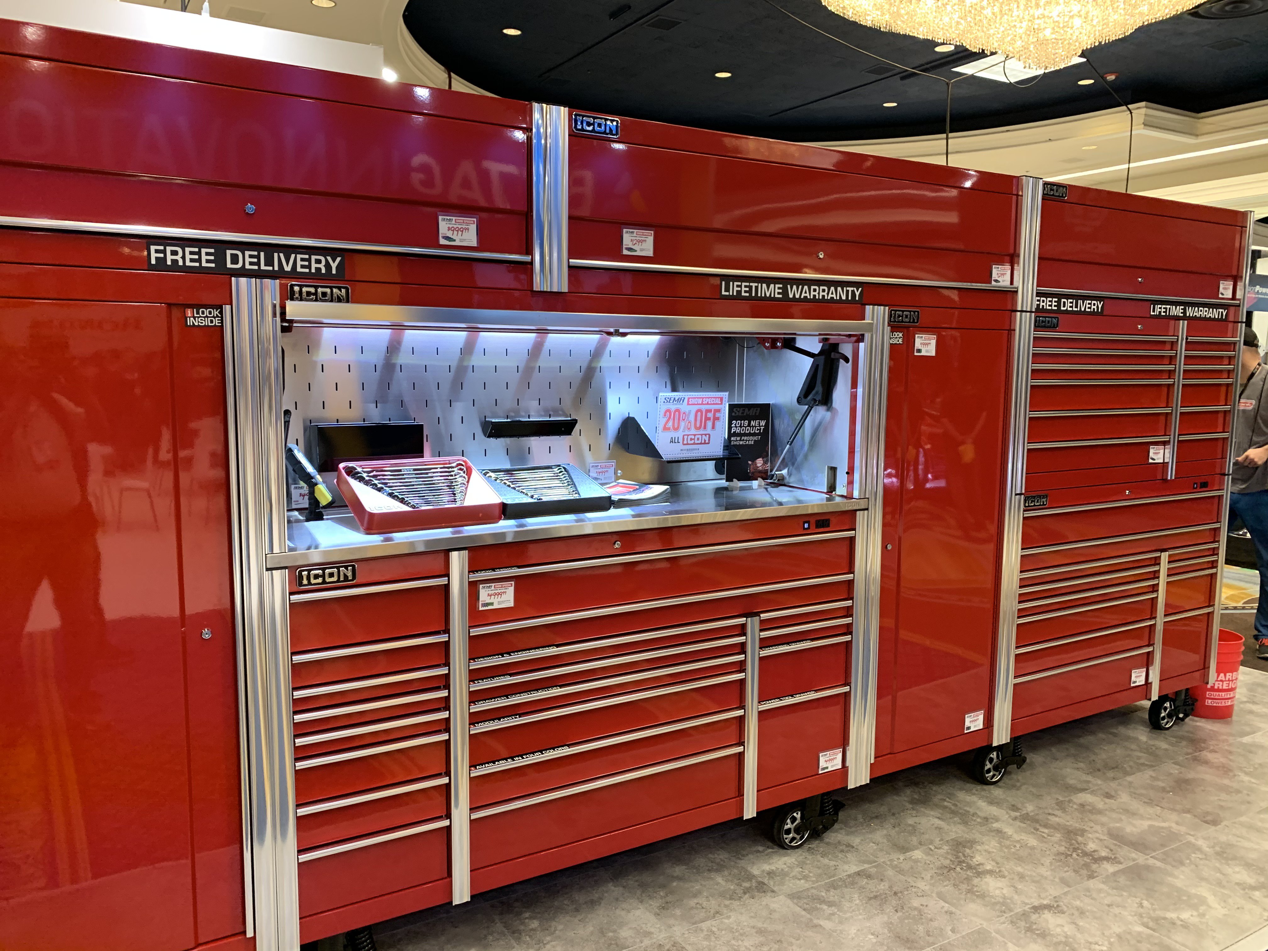
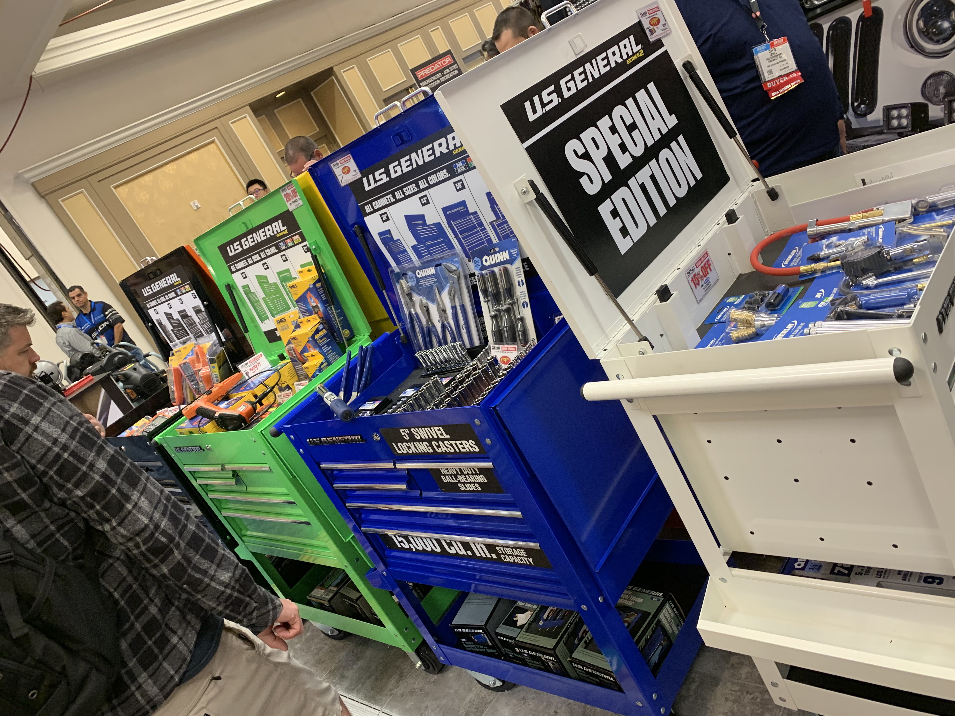
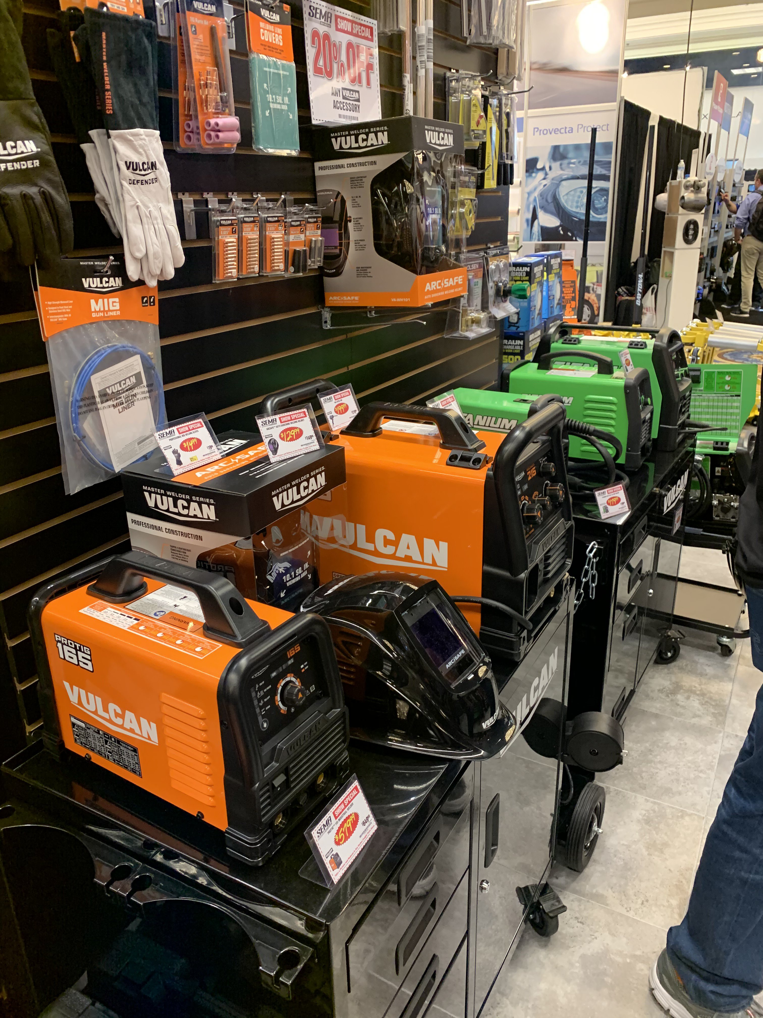
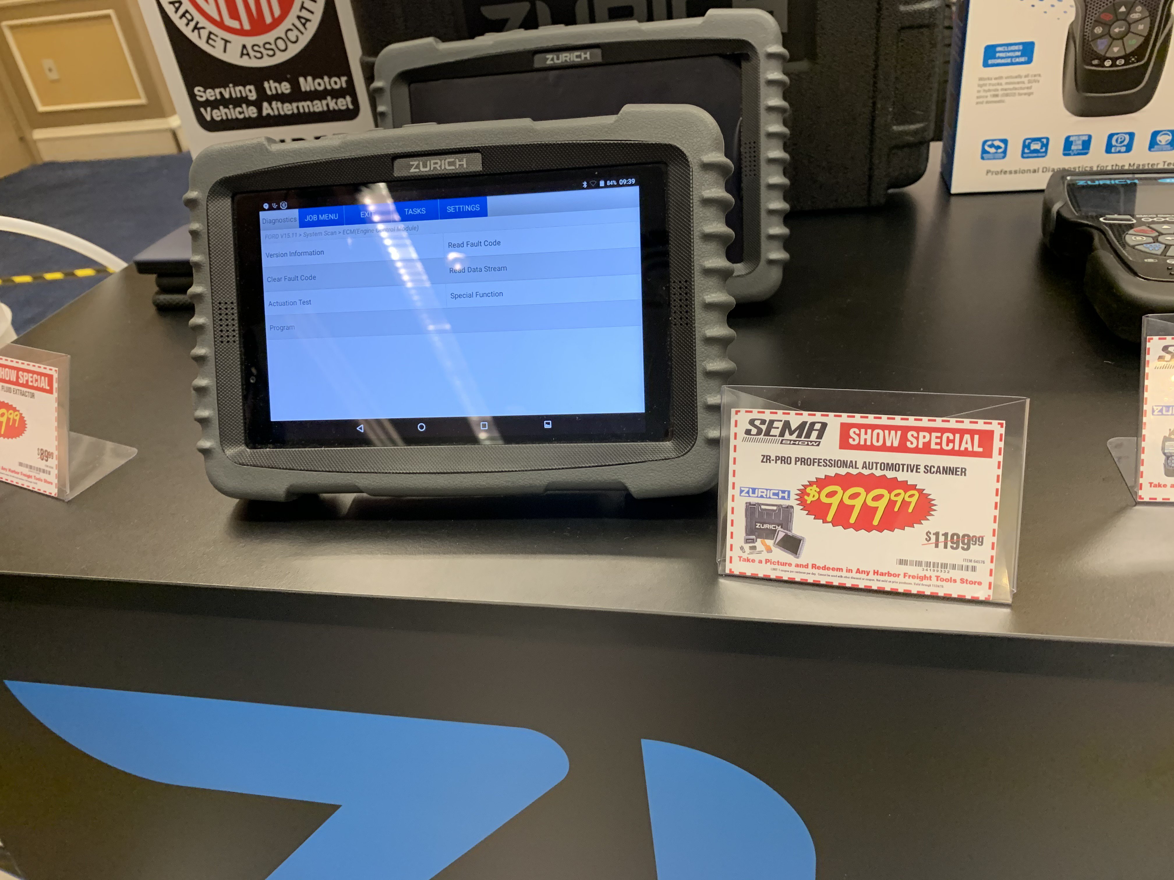
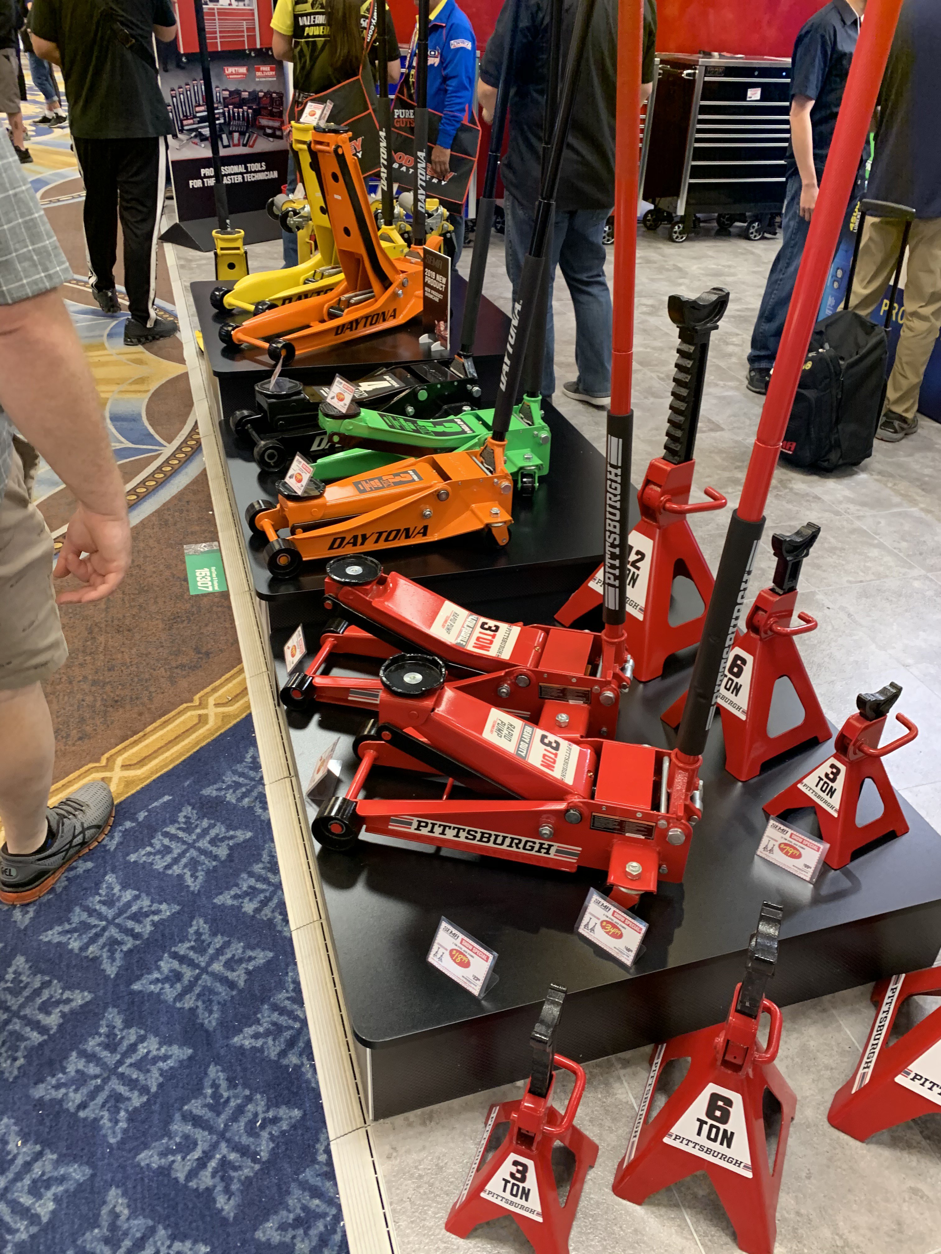
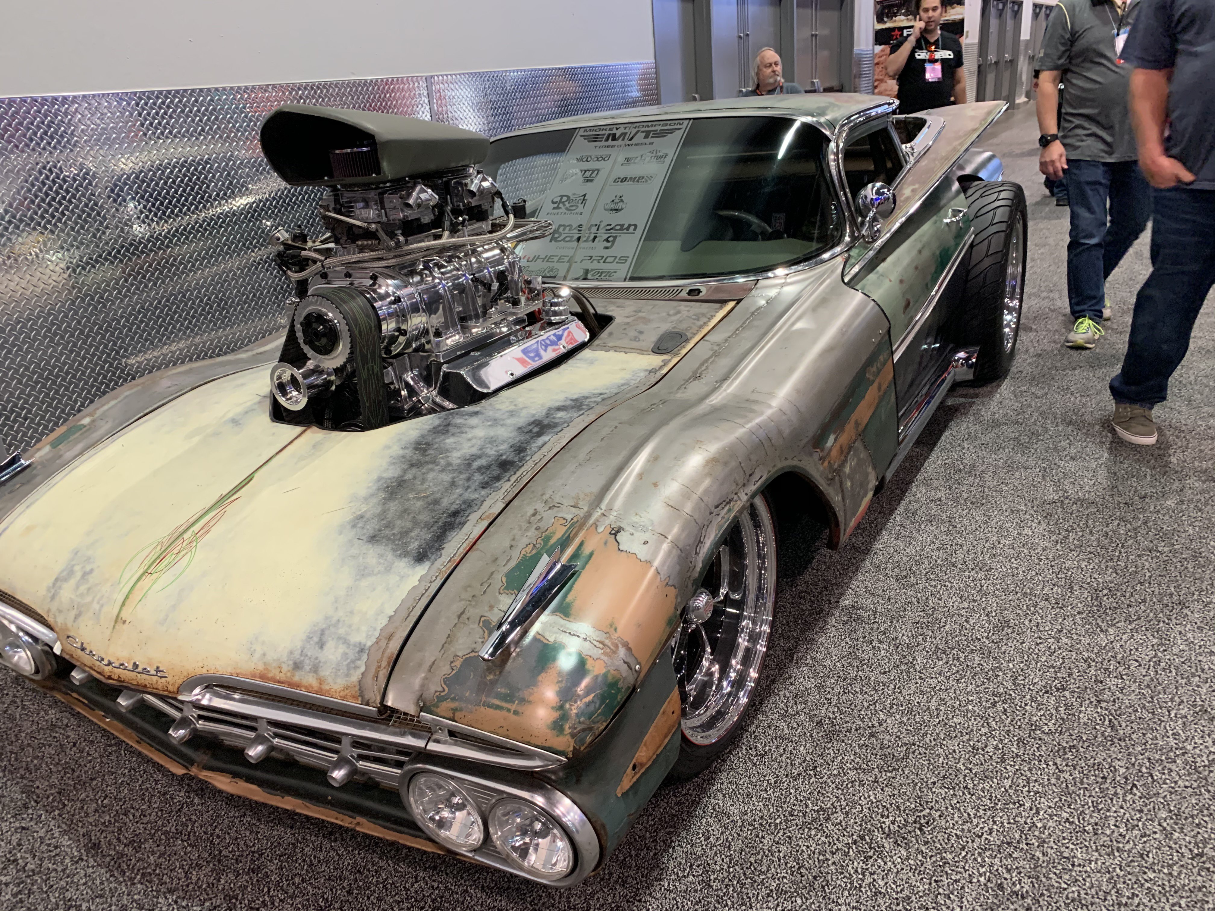
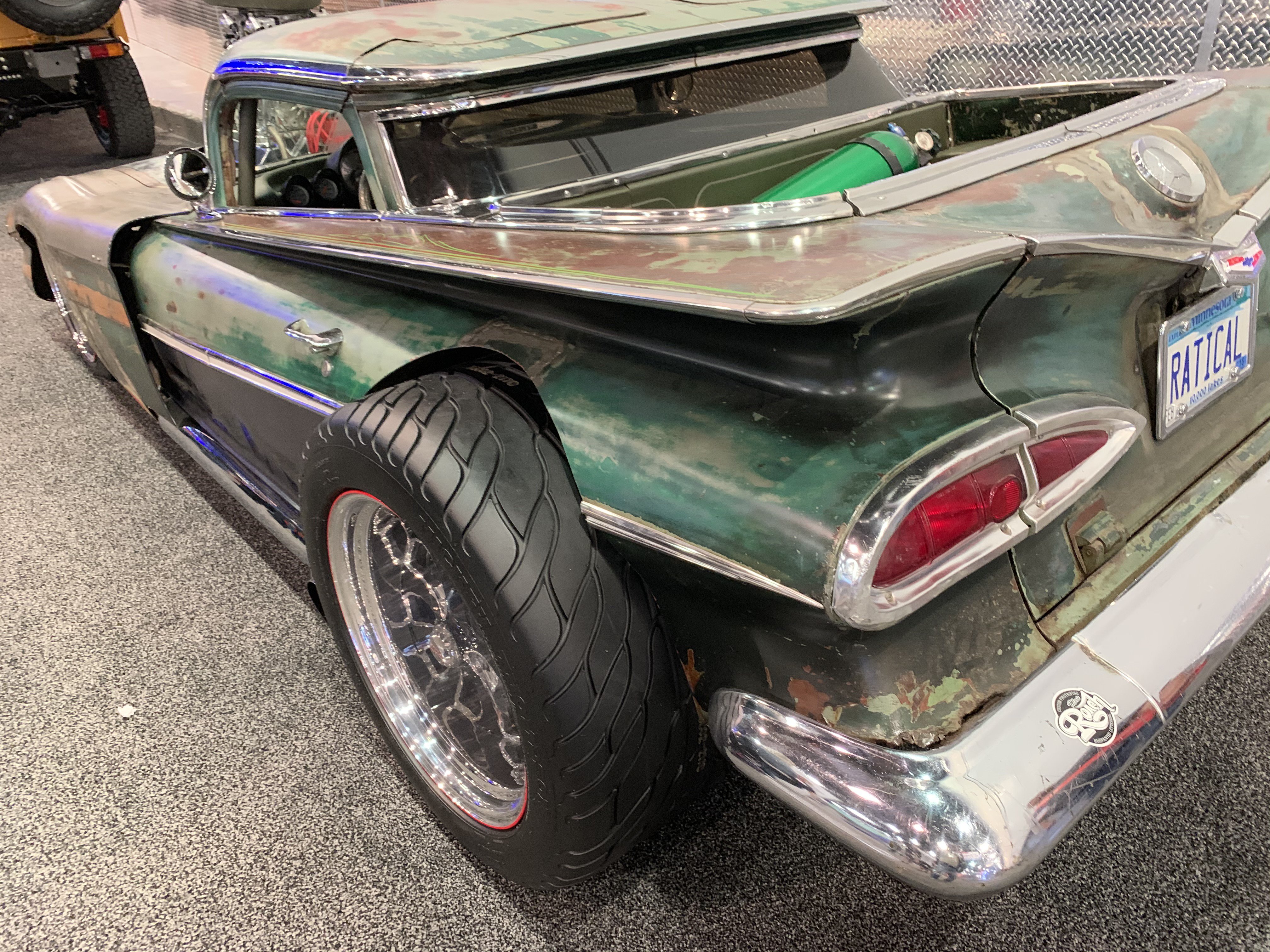
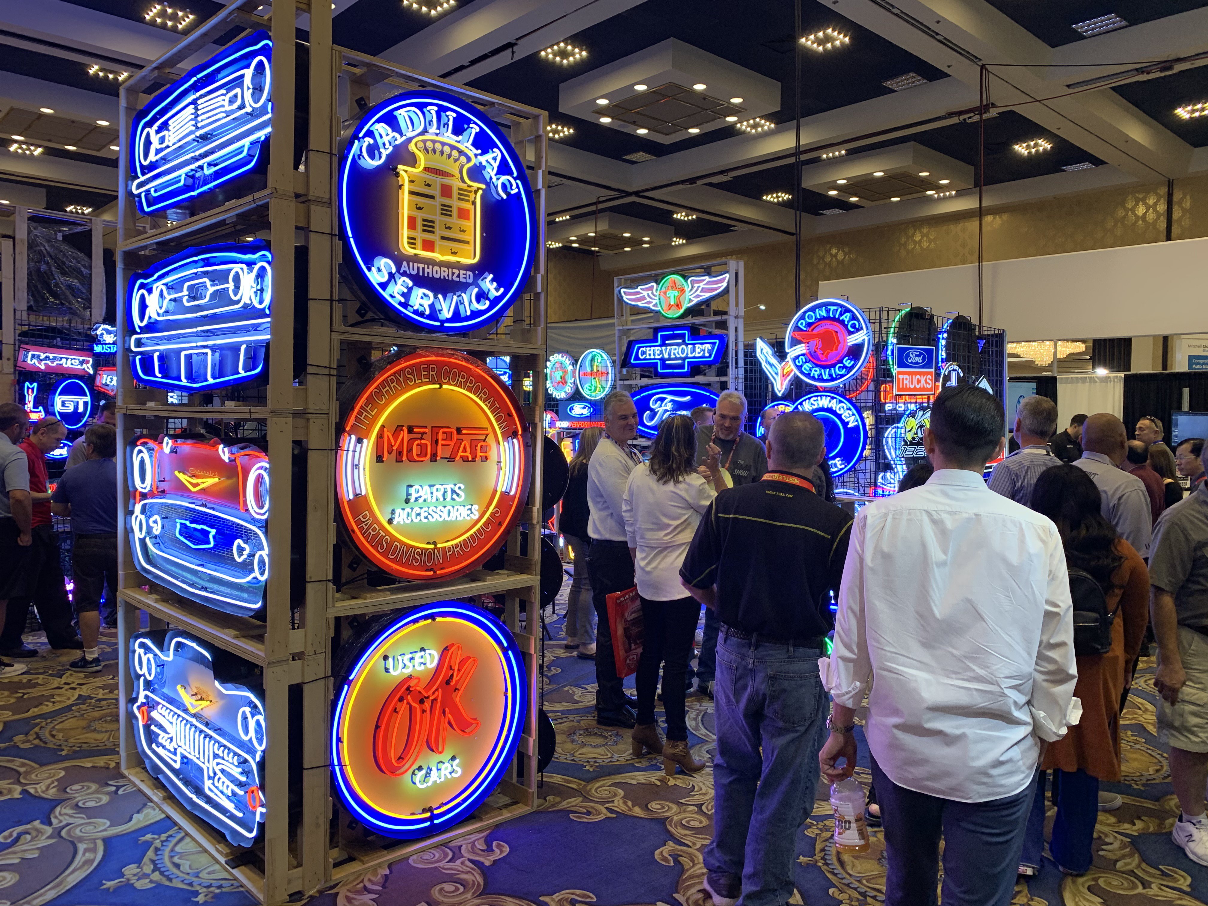
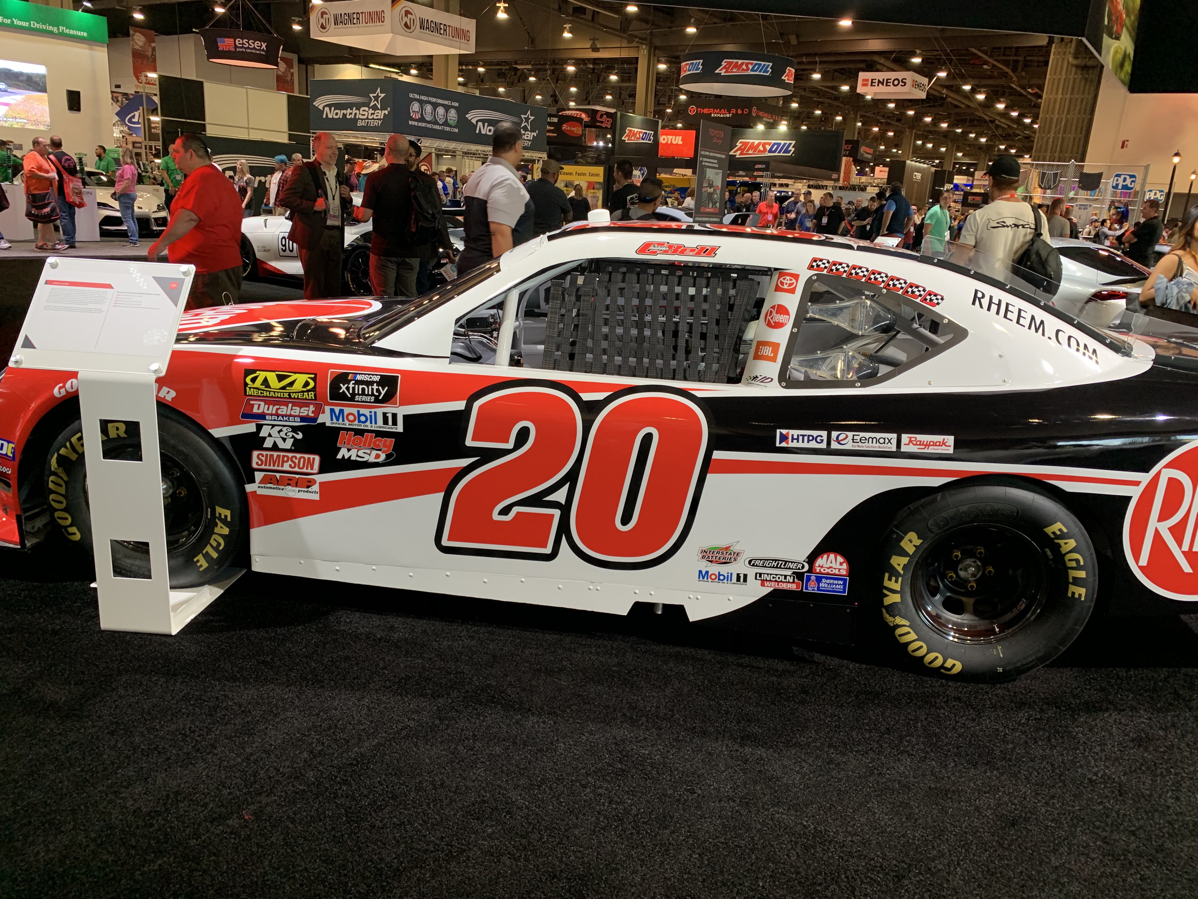
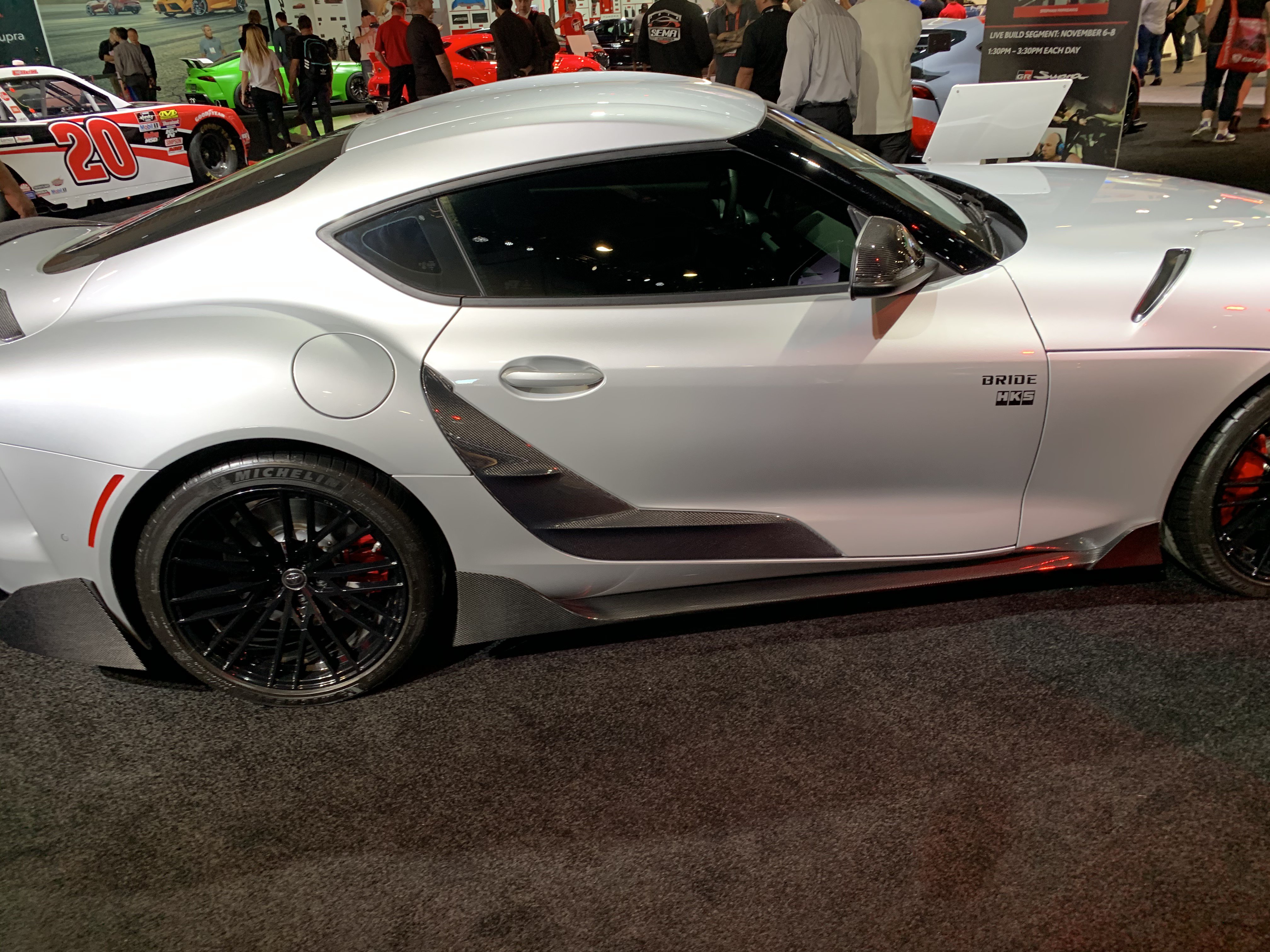
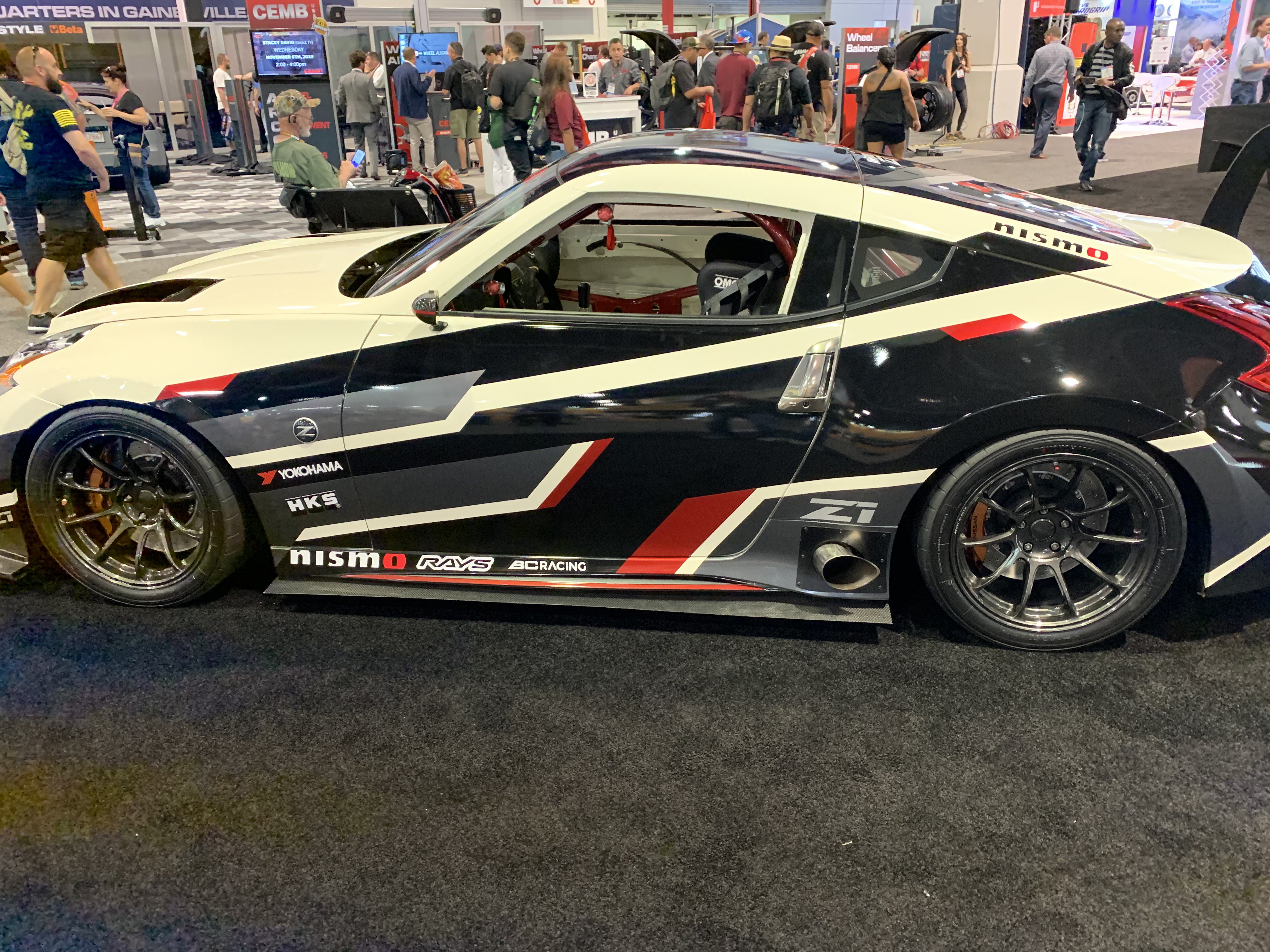
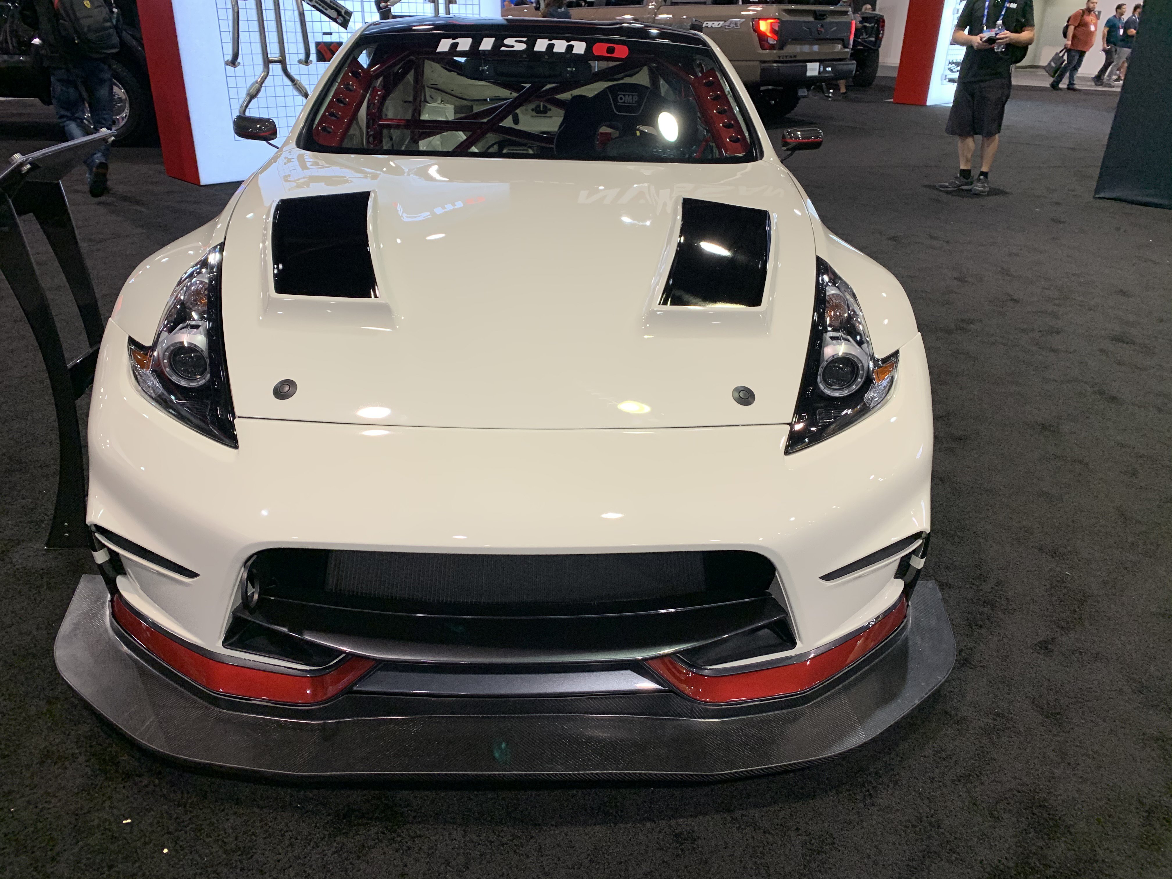
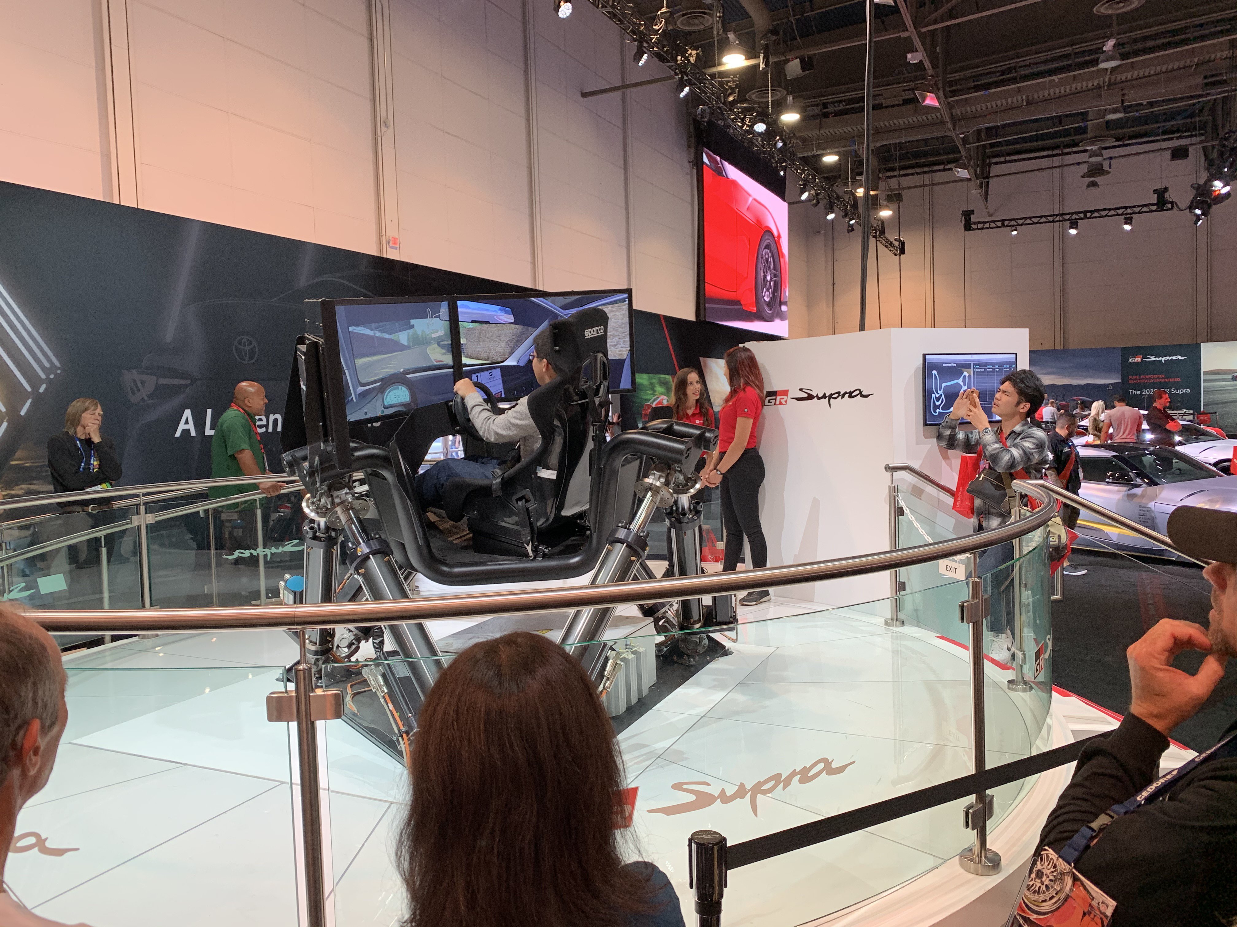
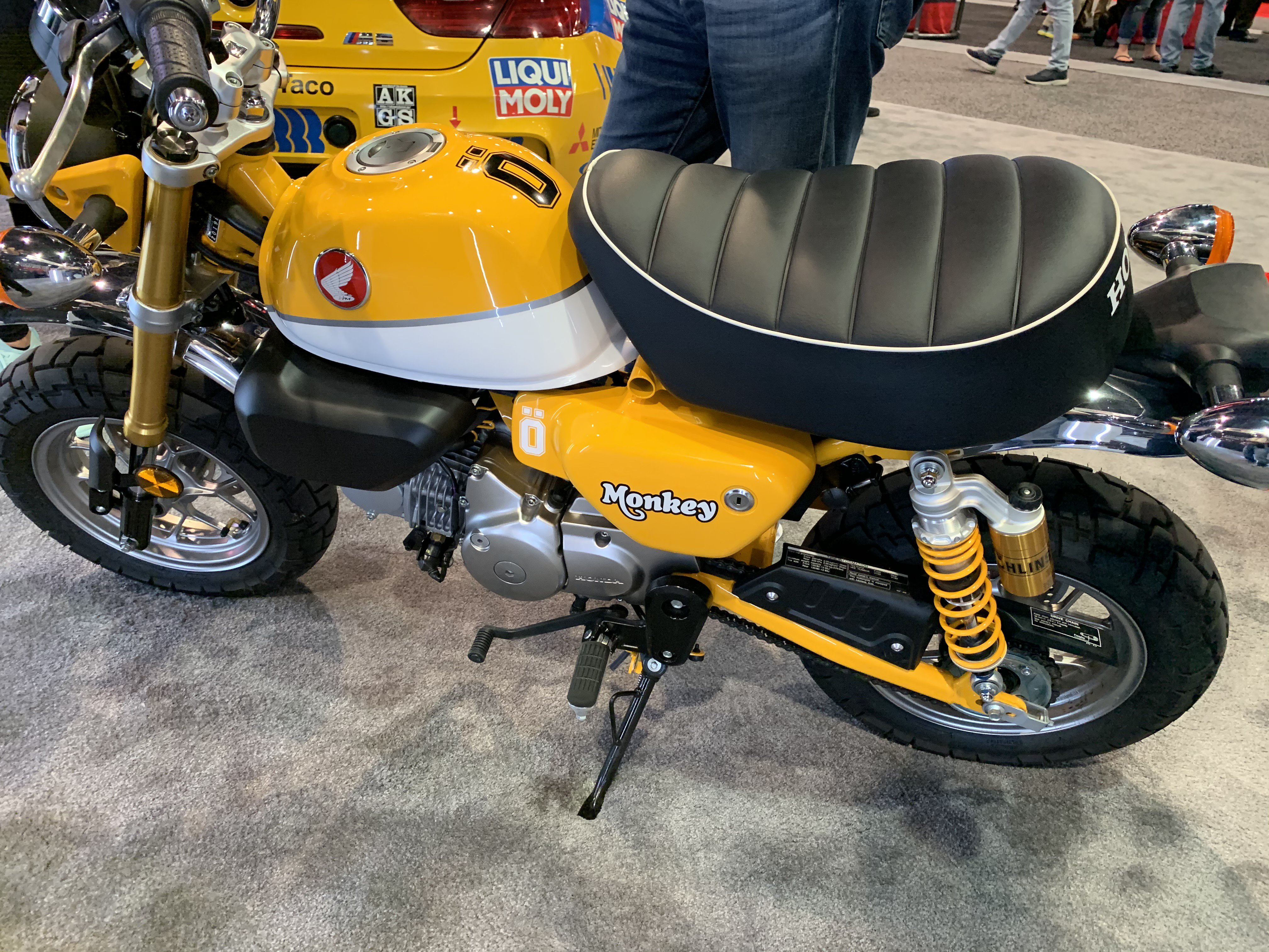
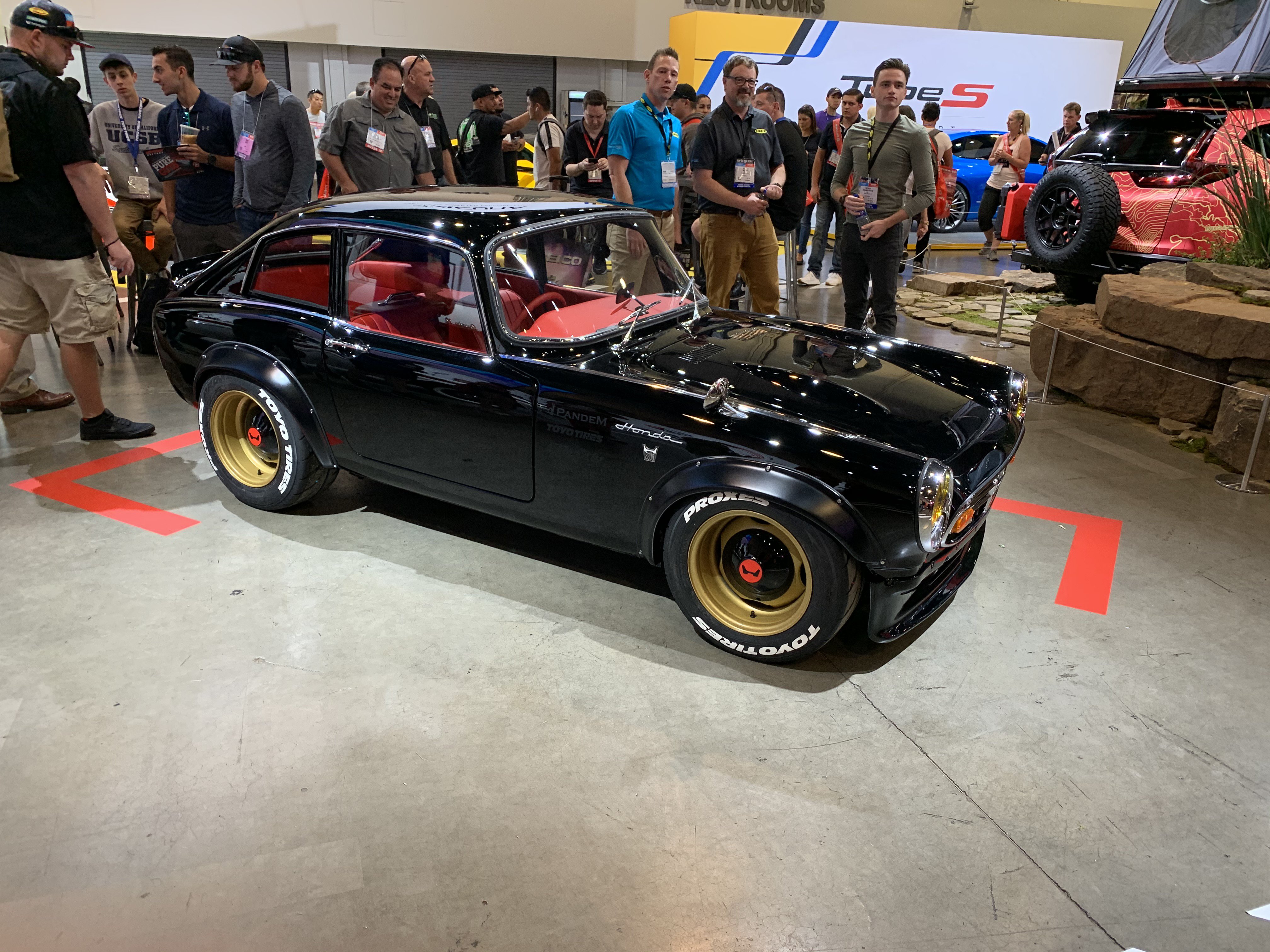
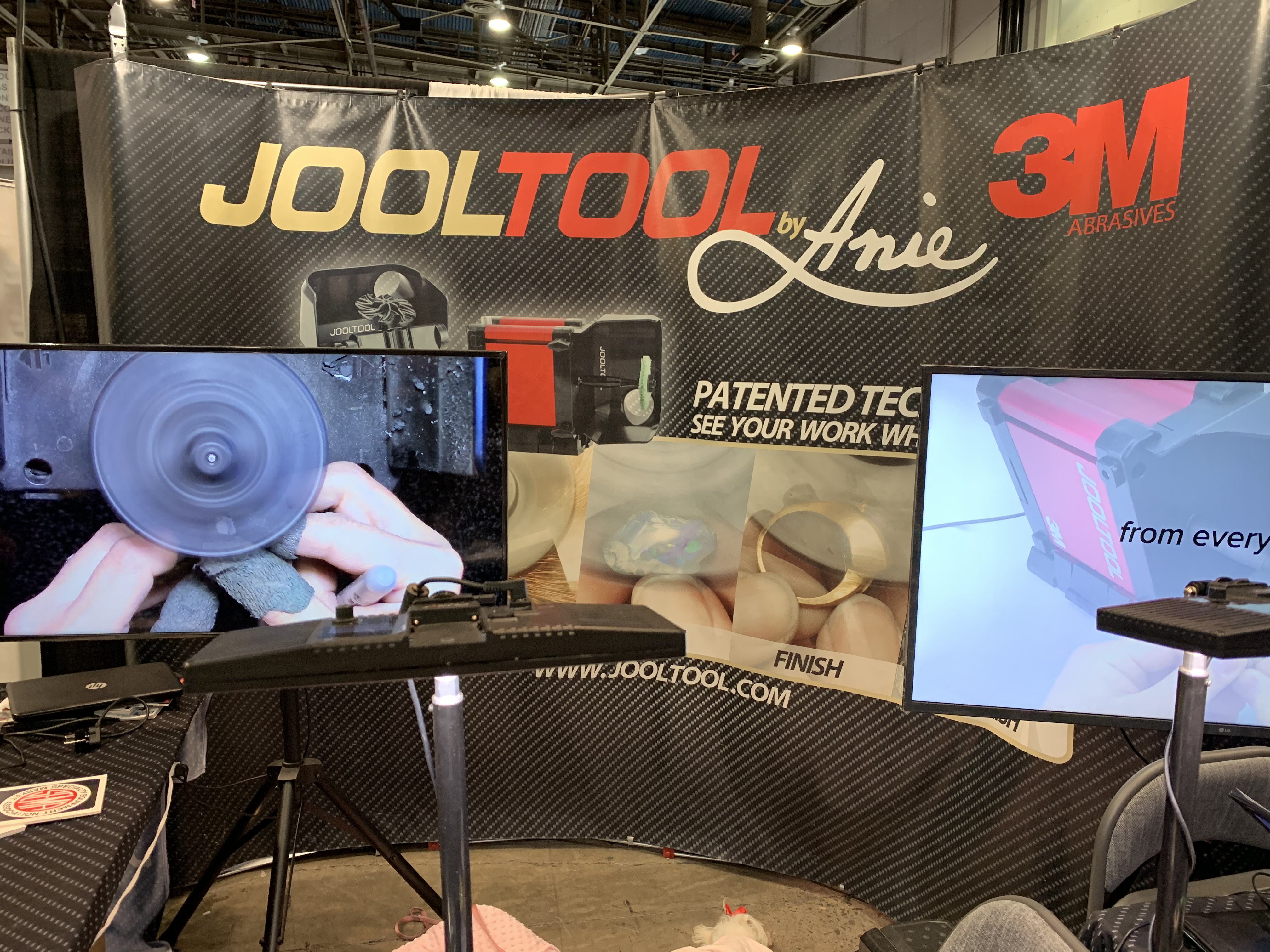
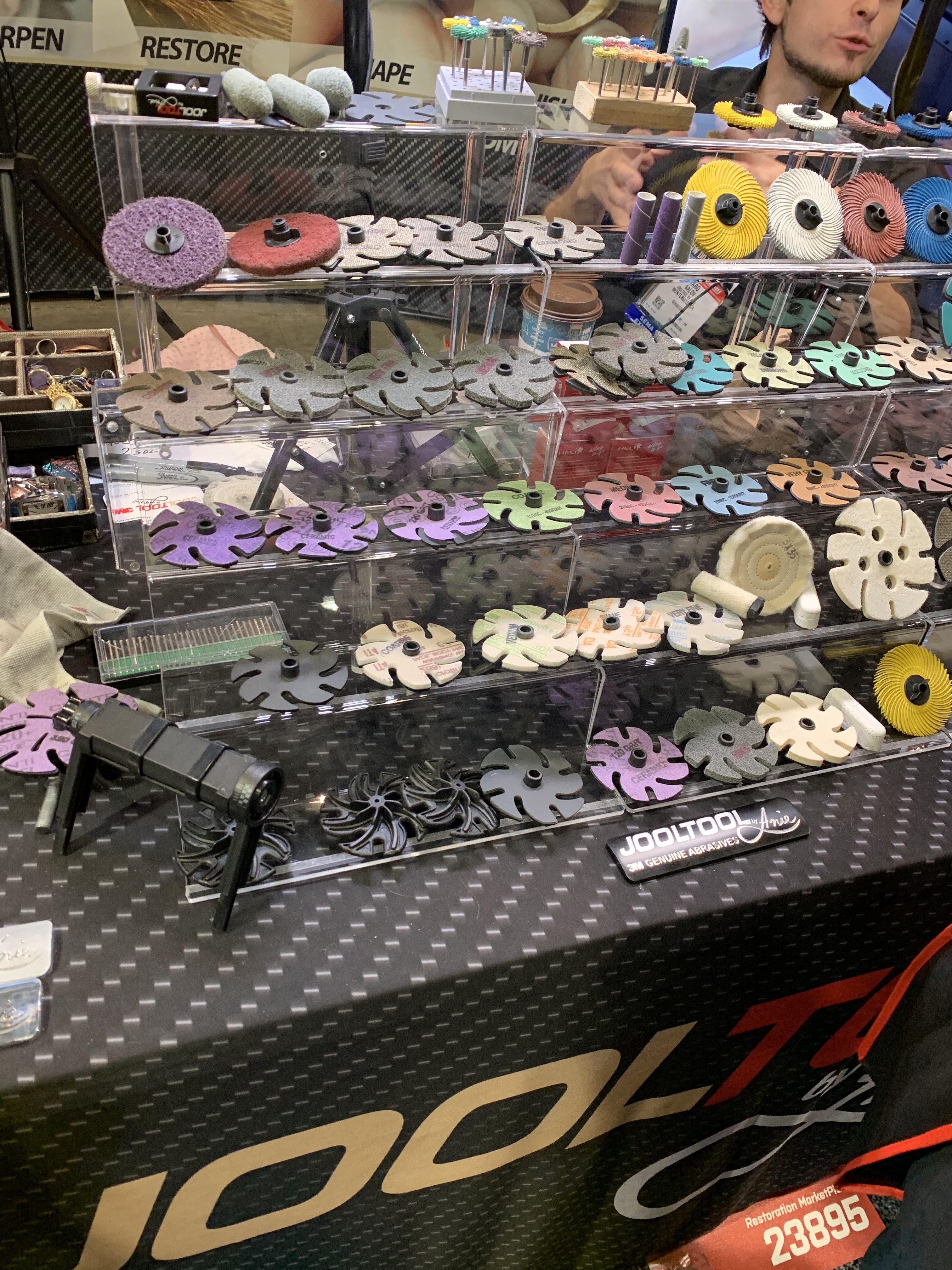
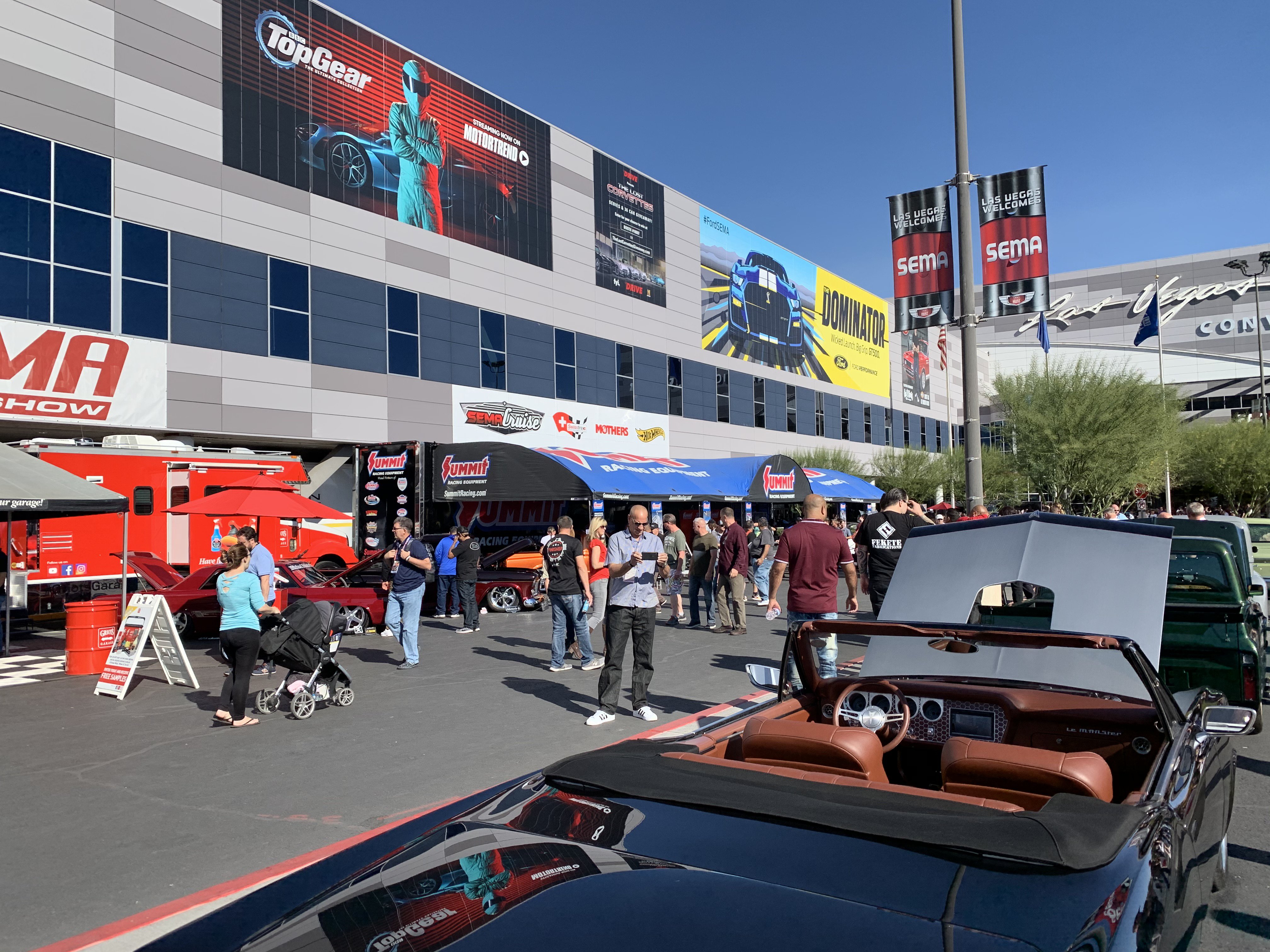
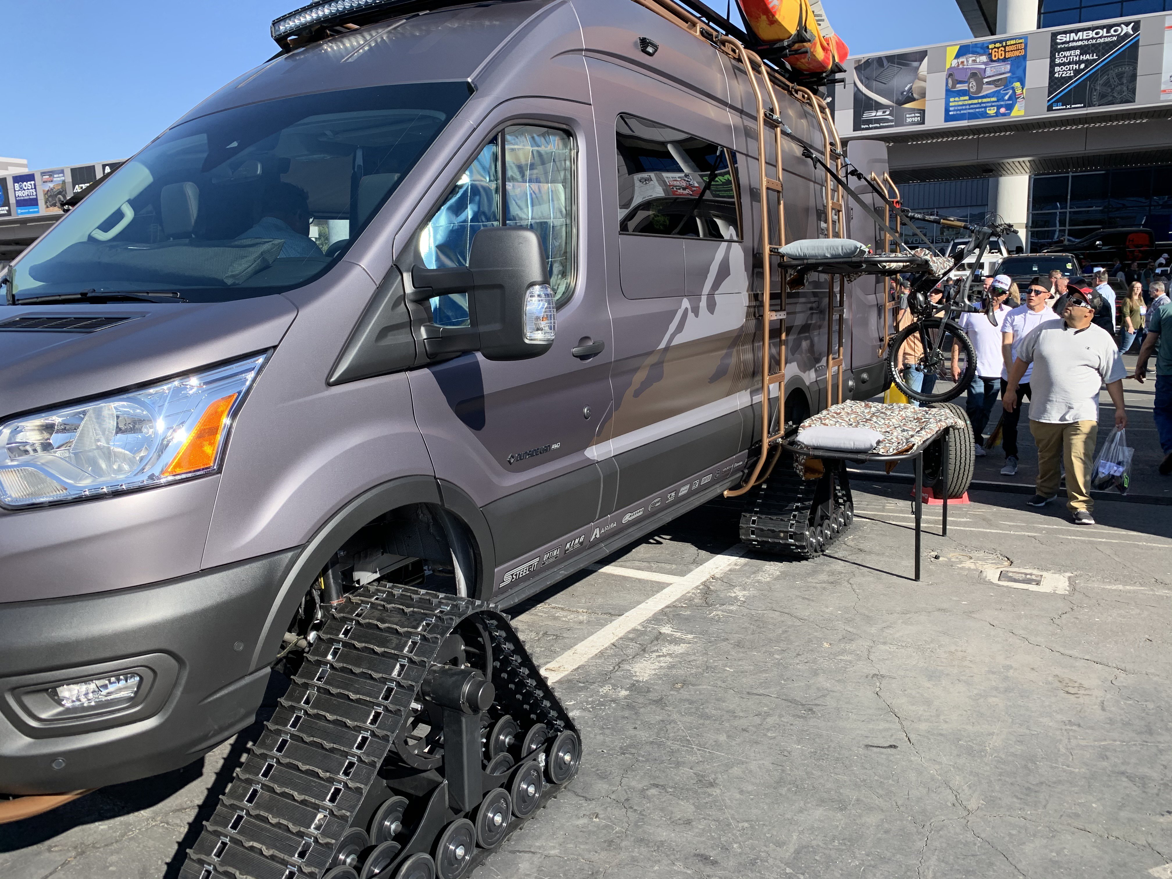
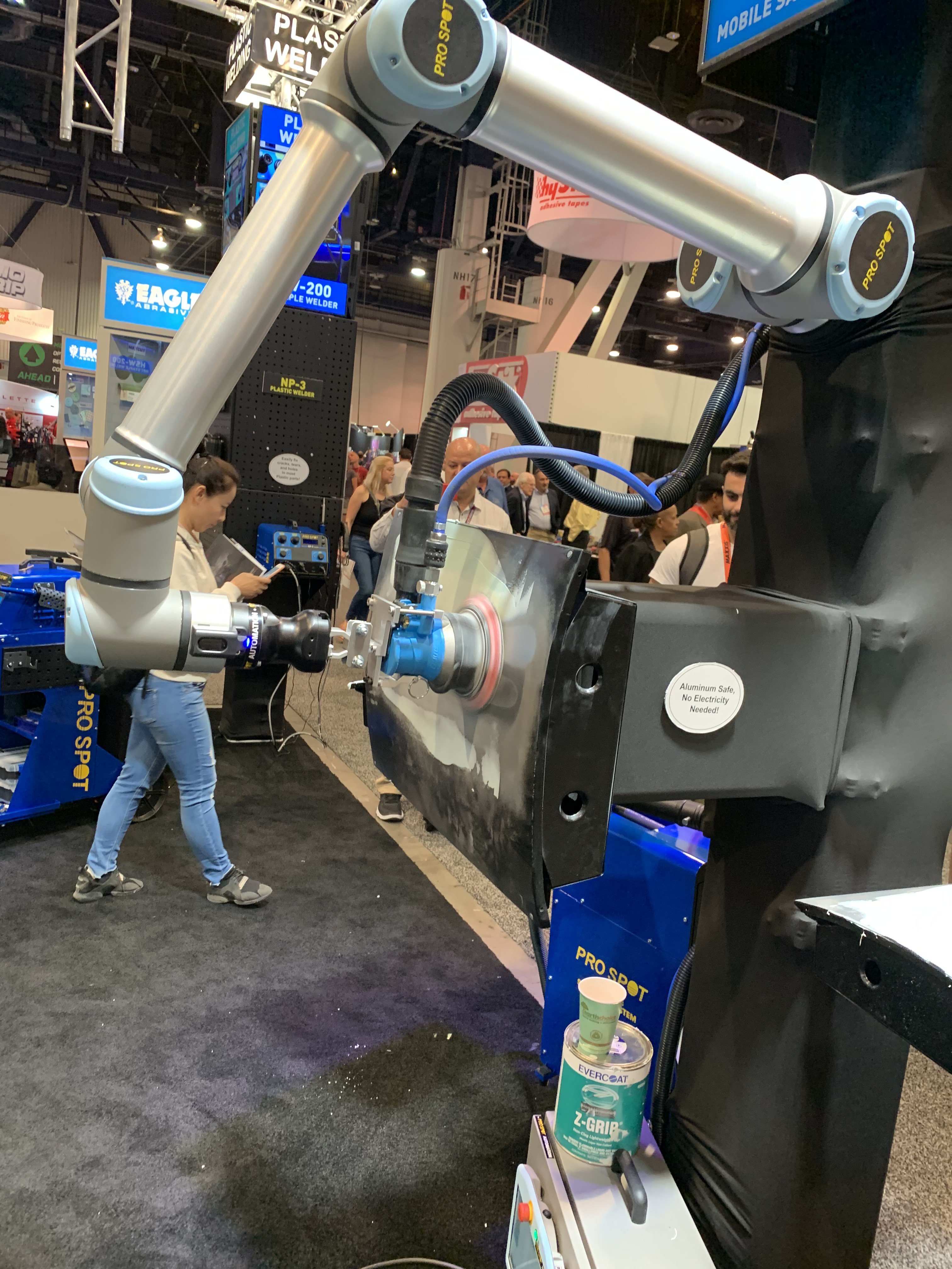
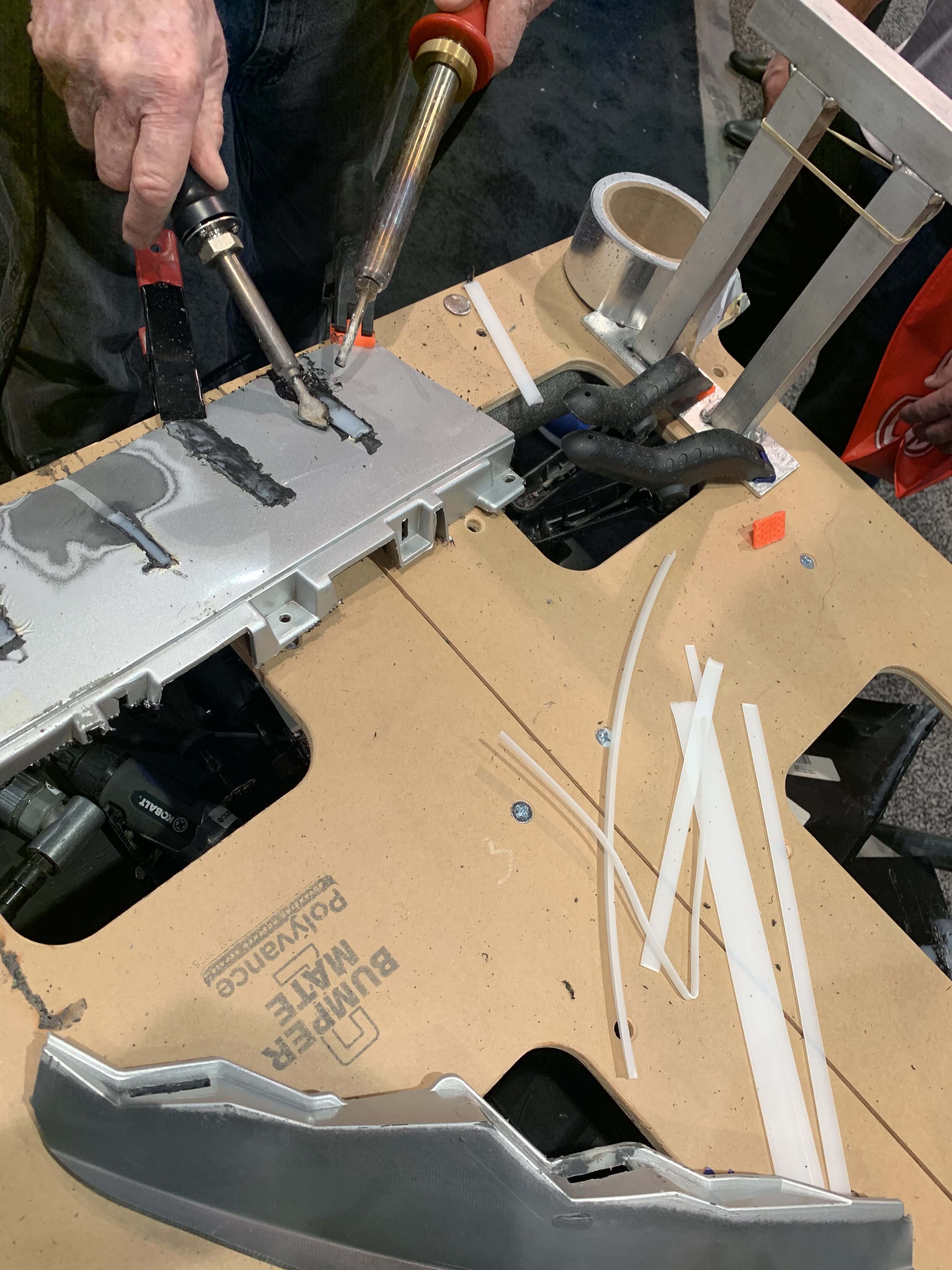
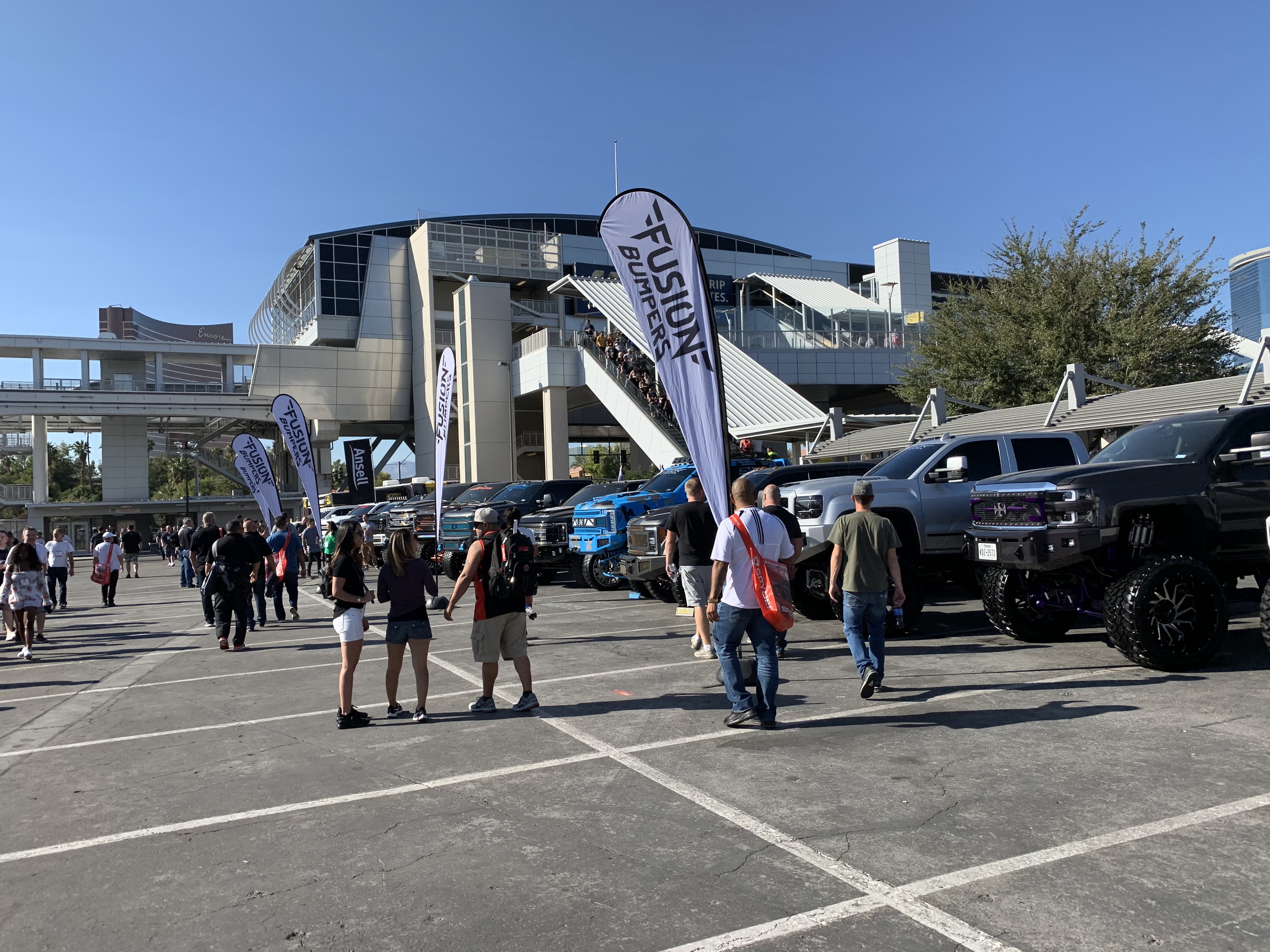
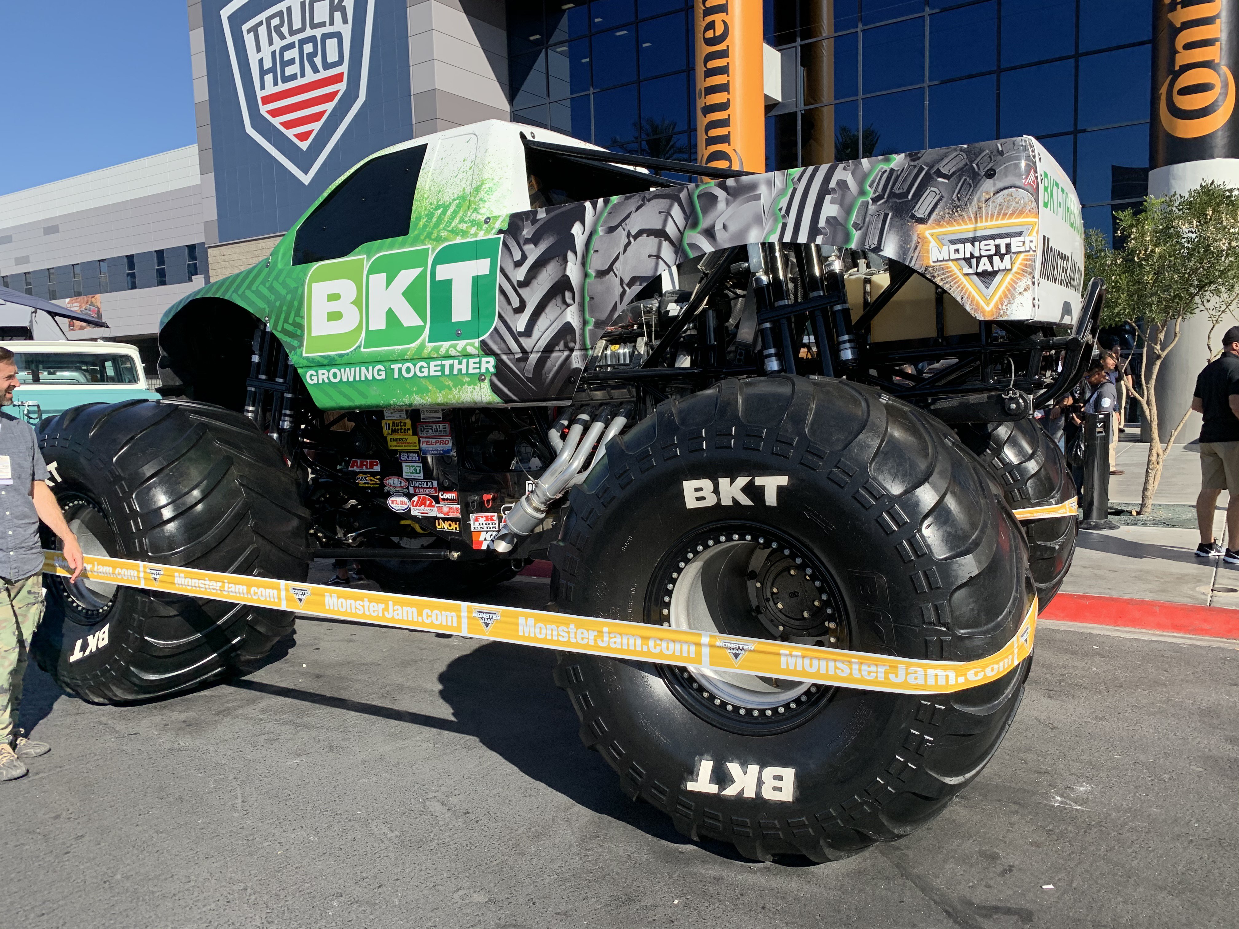
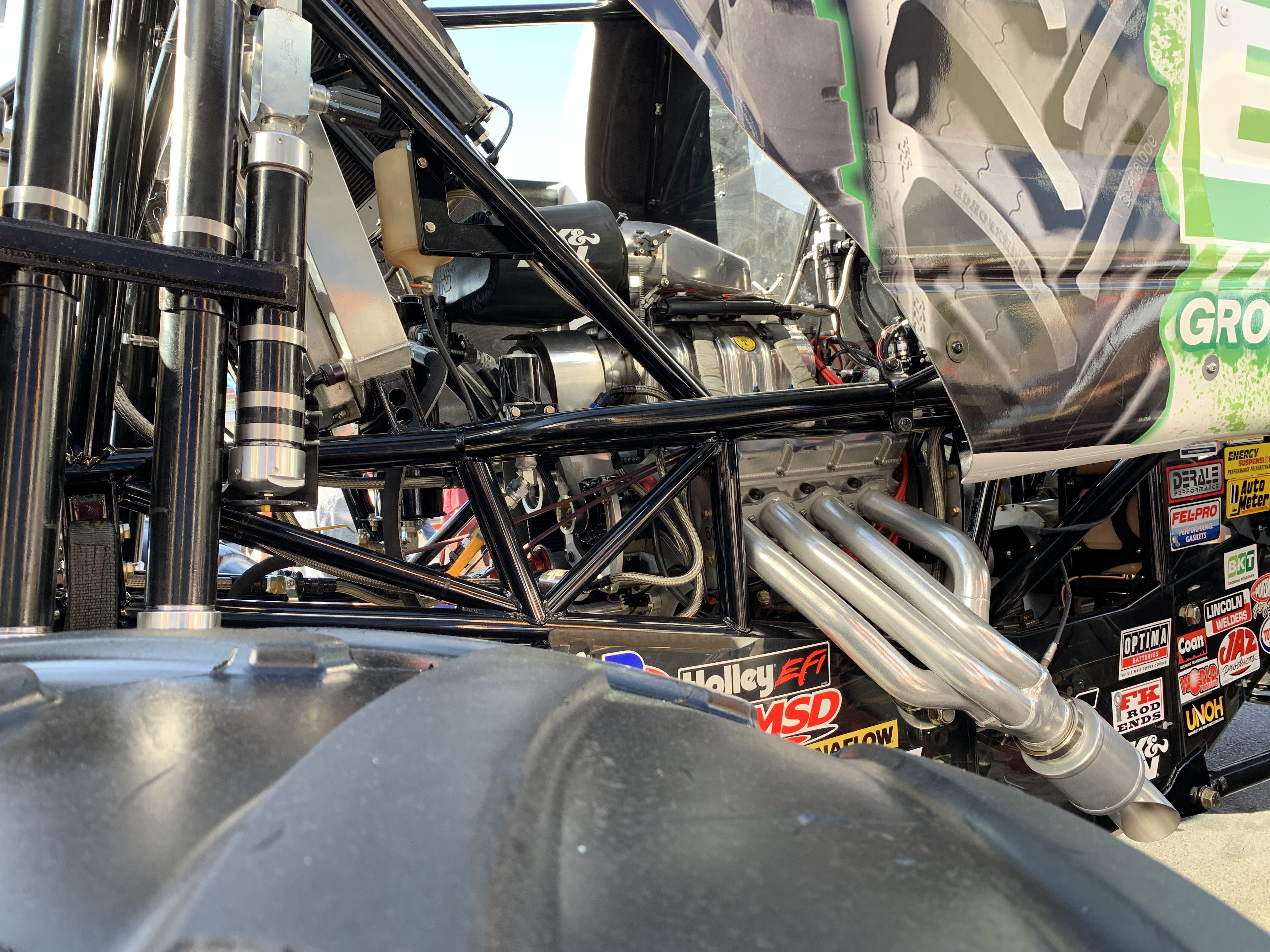
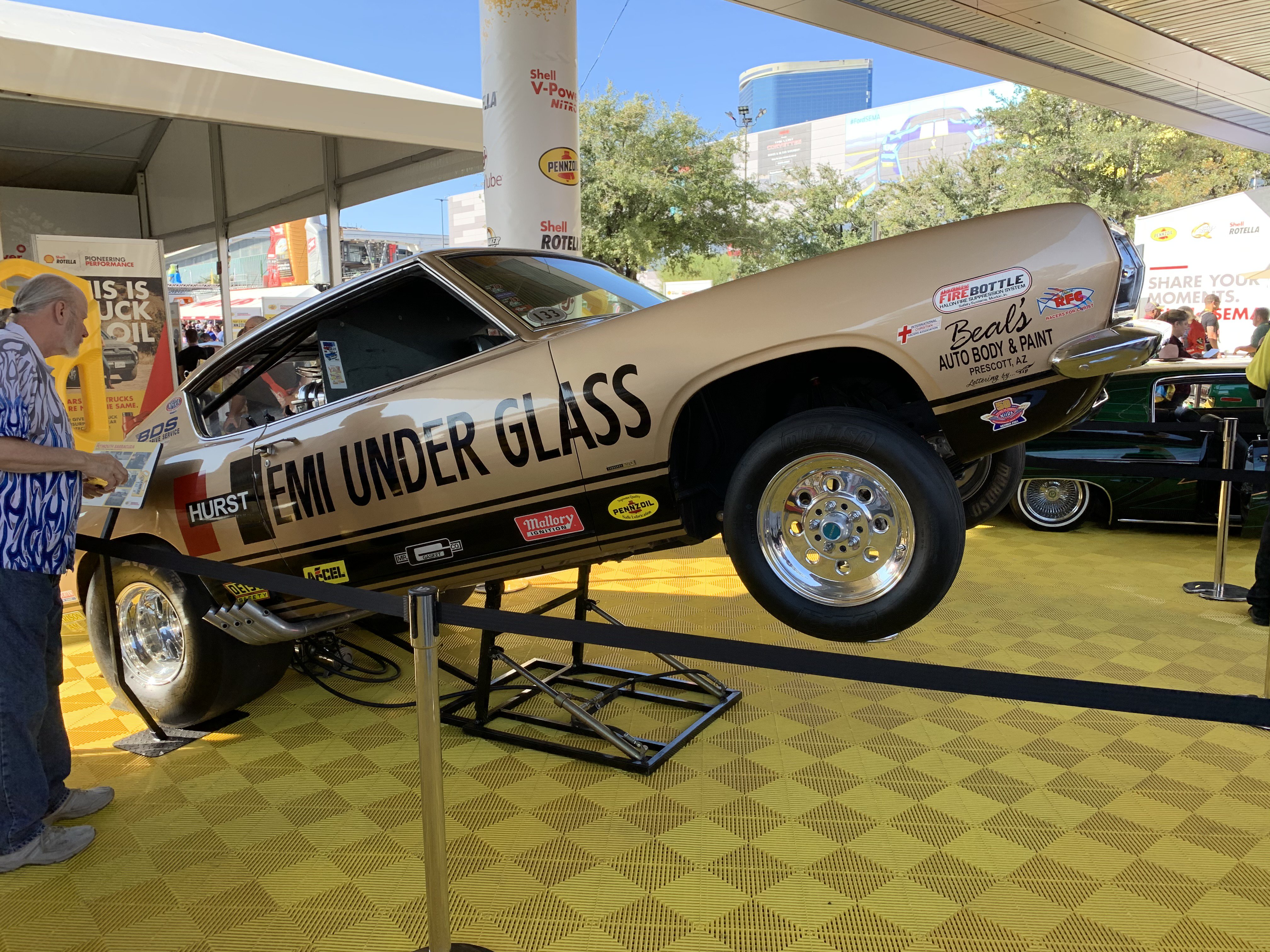
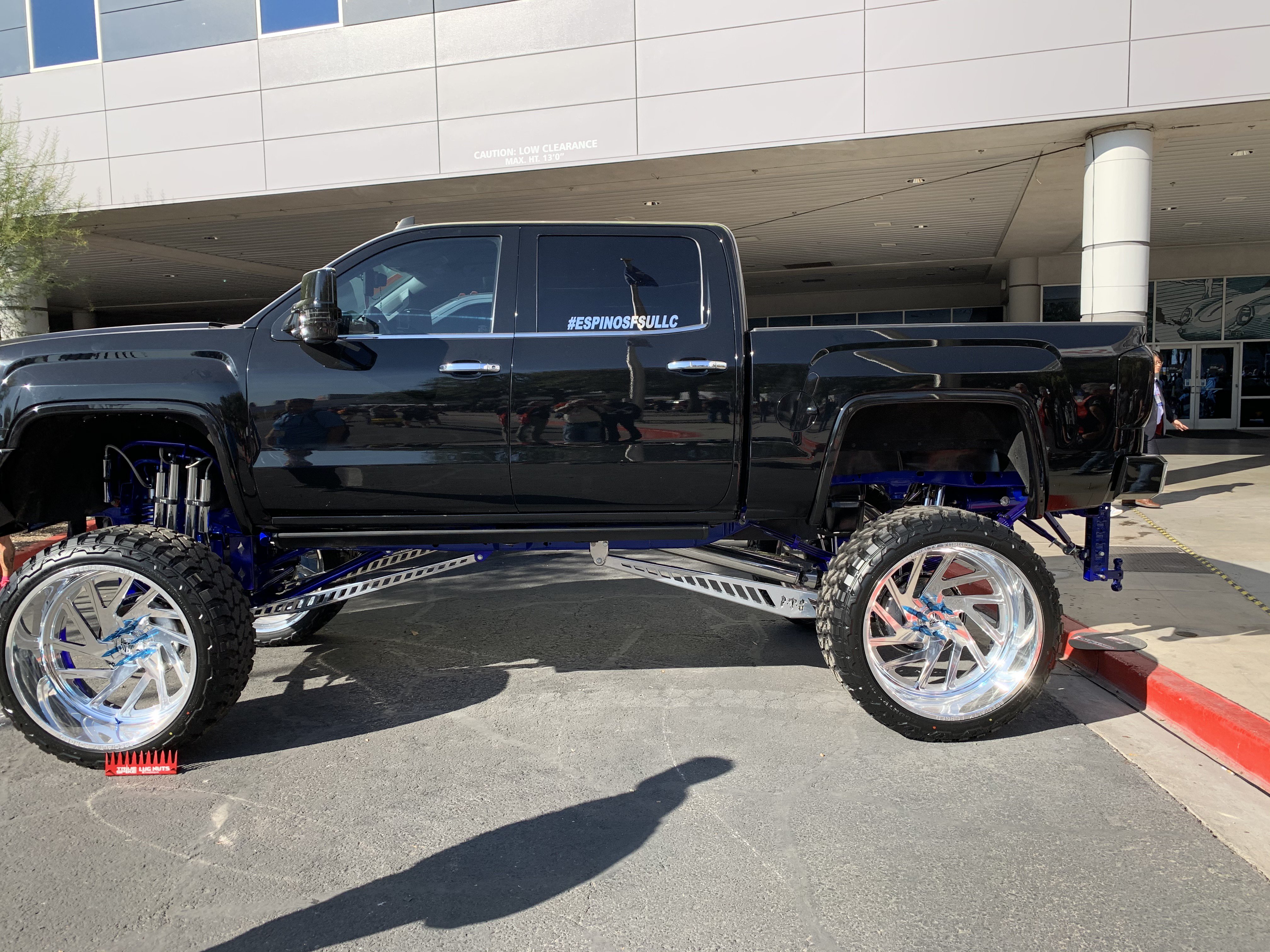
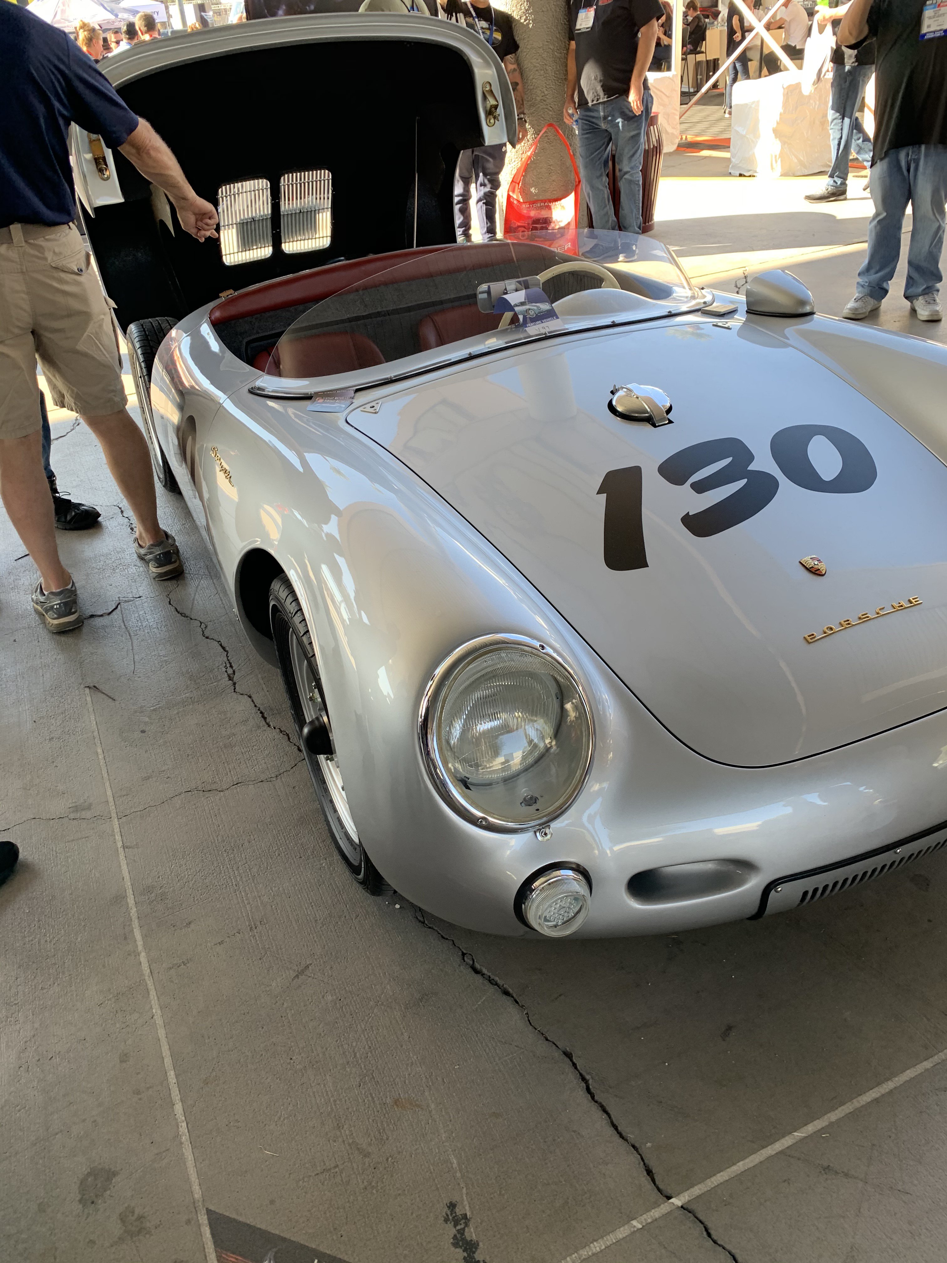
Just returned from the Sema Show 2019. The Sema Show gets bigger and bigger every year. This 240z took part in the Optima Ultimate Street Car event. It had a Webber carbs and slightly modified suspension. Early Datsun Roadster with a Honda twin cam motor conversion with fender flares. Four passenger dune buggy A 240Z racer with carbon fiber body parts. Powered with a Chevy LS motor. With this kit, you can pull dents without grinding your paint -Glue Dent Repair Kit for $600. Water jet Cutting Machine-Note the cutout samples on the table. The very popular John Force 300mph Funny Car I had Lunch at one of the many Sema Food Trucks. the long line of customers Spicy Ribeye steak with rice for $12. Ymmmm! 1970 replica of Pete Brock's Datsun 510 The spec sheet of the 510. Harbor Freight introduced their new tool line. Their lifetime ICON tool box costs $10,000 but remember Harbor Freight usually has 20% discount coupons at their stores. The box was very well made and about half the price of a Snap On similar one. Also had ratchets,sockets, wrenches,etc. Their line of tool carts. Their MIG and TIG welders were low priced too. Their Full Function Scanner with Blue Tooth was only $999 perfect of the Do It Yourselfer. Floor jacks and jack stands Beautiful Old Datsun Roaster With a late model Nissan Twin Cam motor. Mobile Spray Paint Booth Had fresh air intake and exhaust filter system for $20,000 for average size booth, A neat Rat Rod '59 Chevy El Camino with supercharged motor Super Low!! Chopped and Shortened This booth has all sorts of Illuminated Car Signs. Toyota Nascar race car 2020 Toyota Supra 370Z with carbon fiber parts NISSAN NISMO Skyline All Wheel Drive Front view Full Functional Race Car Simulator at Supra booth Beautiful Honda Z50 Mini Bike Another Honda 50cc Monkey bike A Wild 65 Ford Van with supercharged motor. Supercharged motor with long headers Old Honda S80 with flares JooTool is a specialized small polisher for restoring small car parts. Also, sharpens knives. 3M provides various grinding, sanding and polishing discs for this machine. Outside the halls, more booths and cars This van had Four Wheel Track drive so it could go almost everywhere. Robot sanding machine made by PRO SPOT. Even had vacuum system to catch the bondo dust. Plastic welding machine with Nitrogen gas to create strong plastic welds plastic welding made by urethane Supply. more cars & people Ford Mustang one wild ride with tire burning etc. More trucks Monster trucks,too Its motor and suspension huge too. Hurst Hemi under Glass Barracuda was there too. Skelton car its supercharged motor High and Might truck 4 x 4 James Dean Replica Porsche covertible Hoogan Pit area and Burn Yard Hoogan put on a Wild Tire Burnout Show but I missed it as I thought it was over. When I was on the top of the Monorail Platform, the Burn Out Show happened. But if you want to see the Show go to: https://www.youtube.com/watch?v=NAzAI8pxyLs Hoogan guys did a preshow walk through and did crazy Burnouts and Drifting there!!!! Now, Back to working on my 240Z
-
Heavy Duty frame rails and connectors
toolman replied to toolman's topic in Gen III & IV Chevy V8Z Tech Board
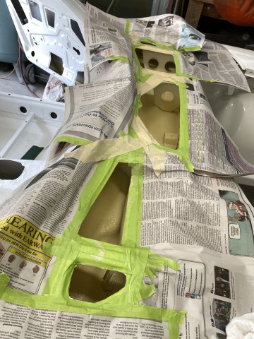
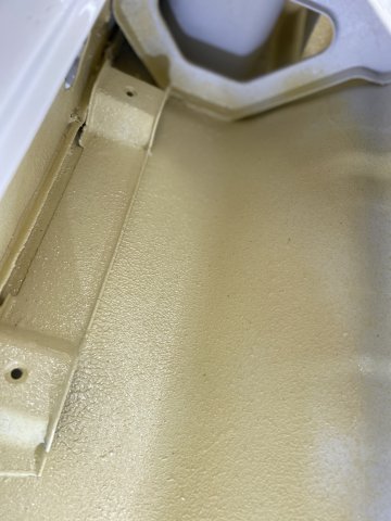
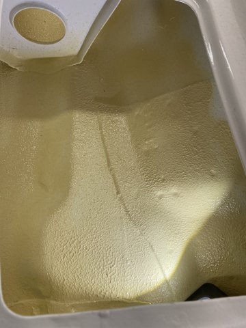
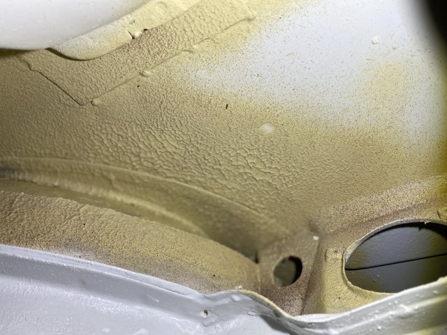
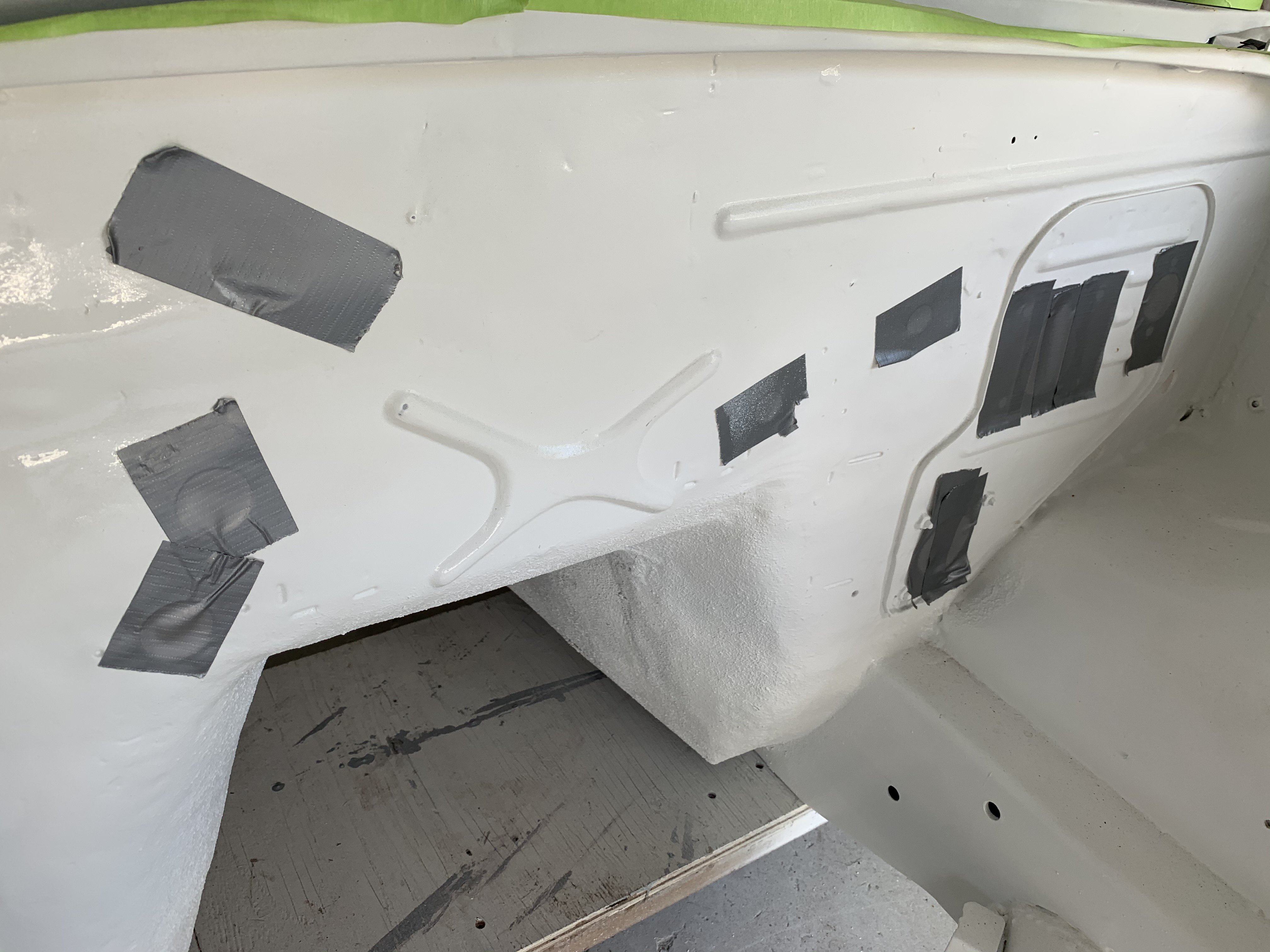
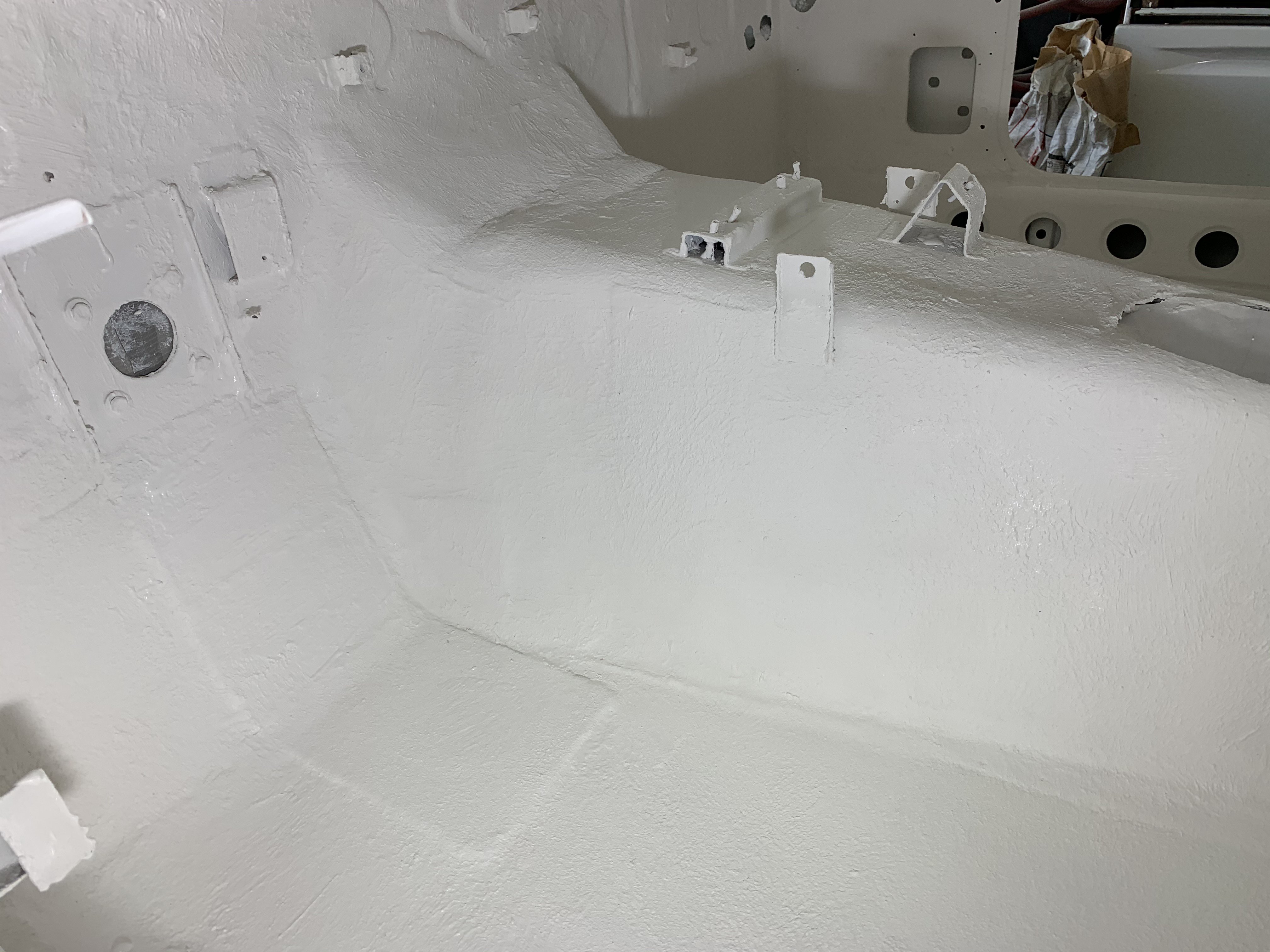
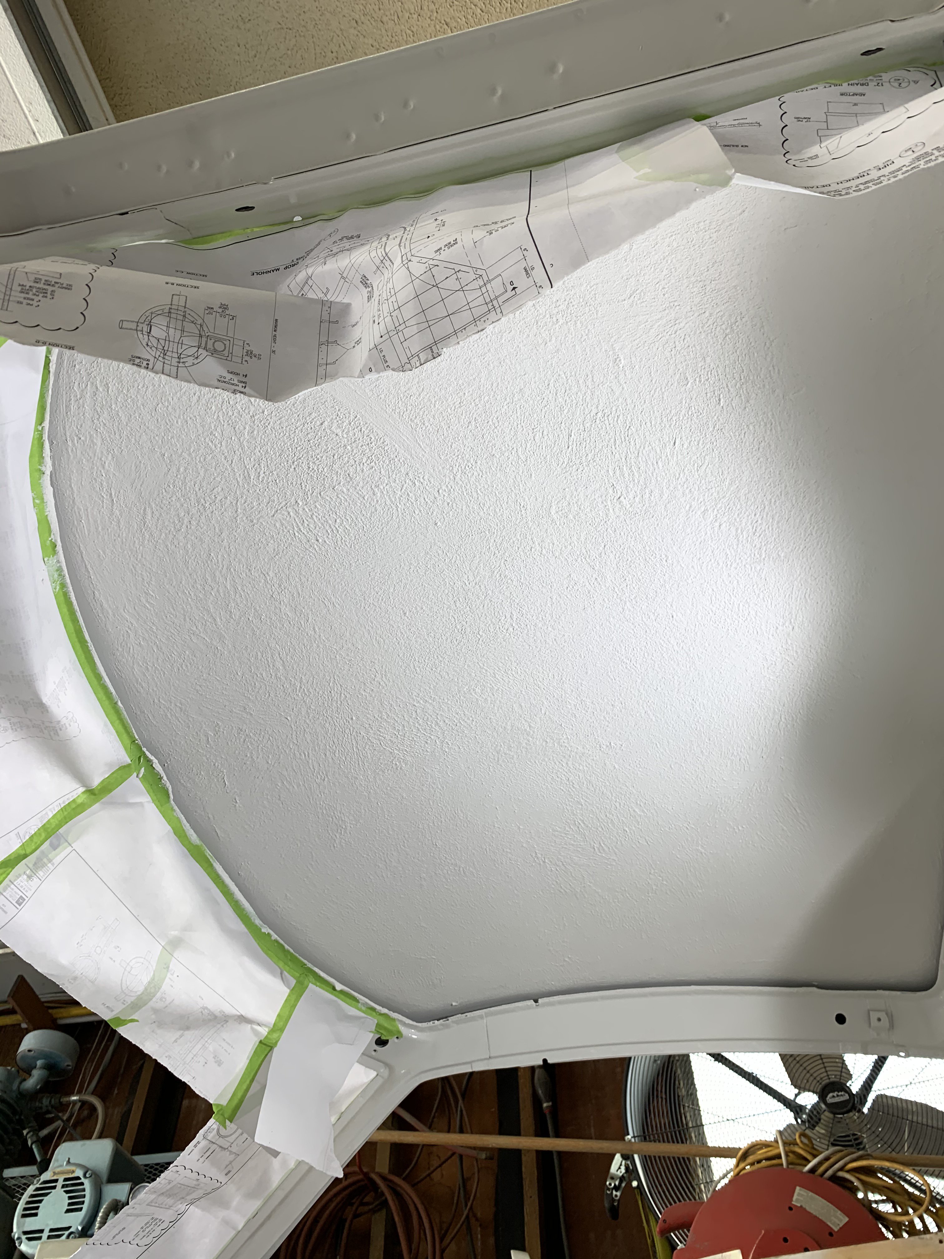
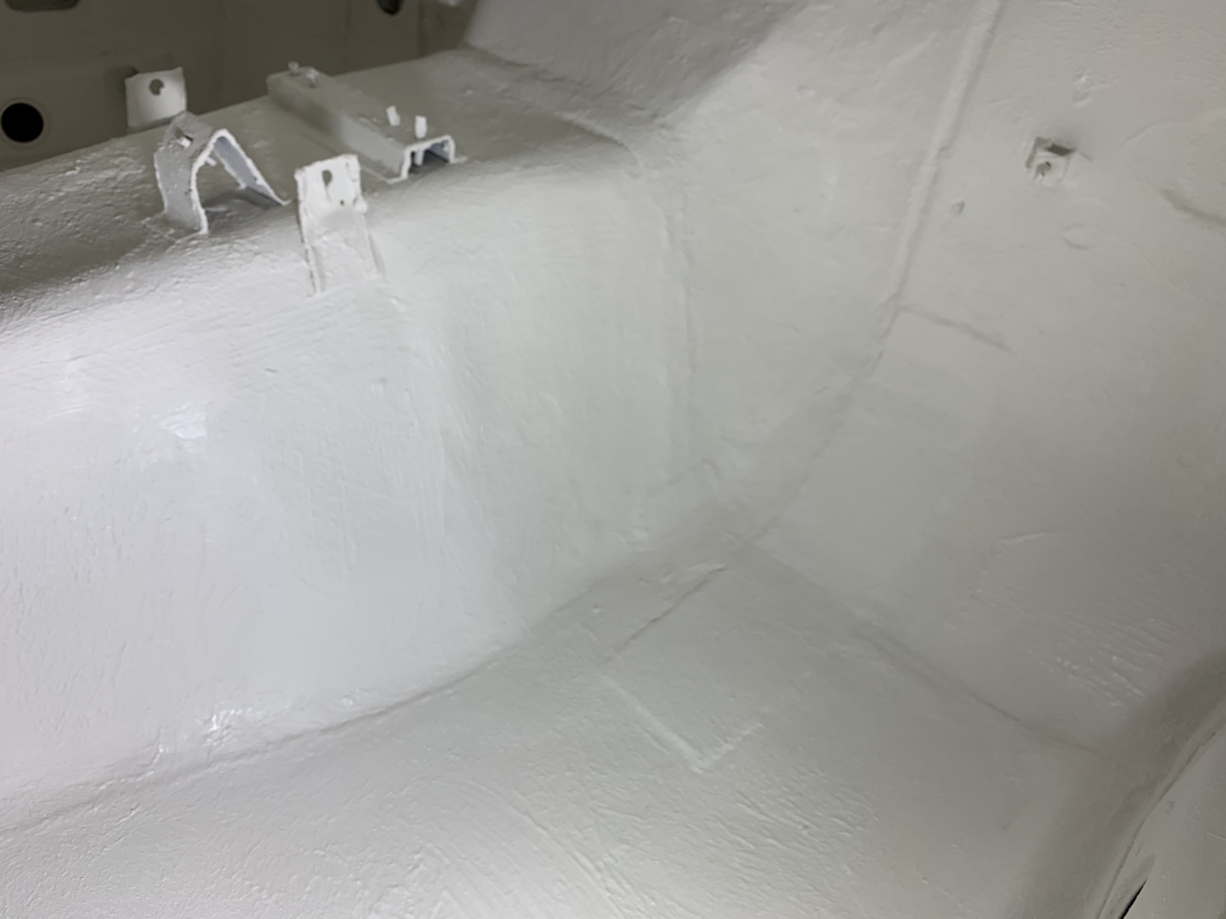
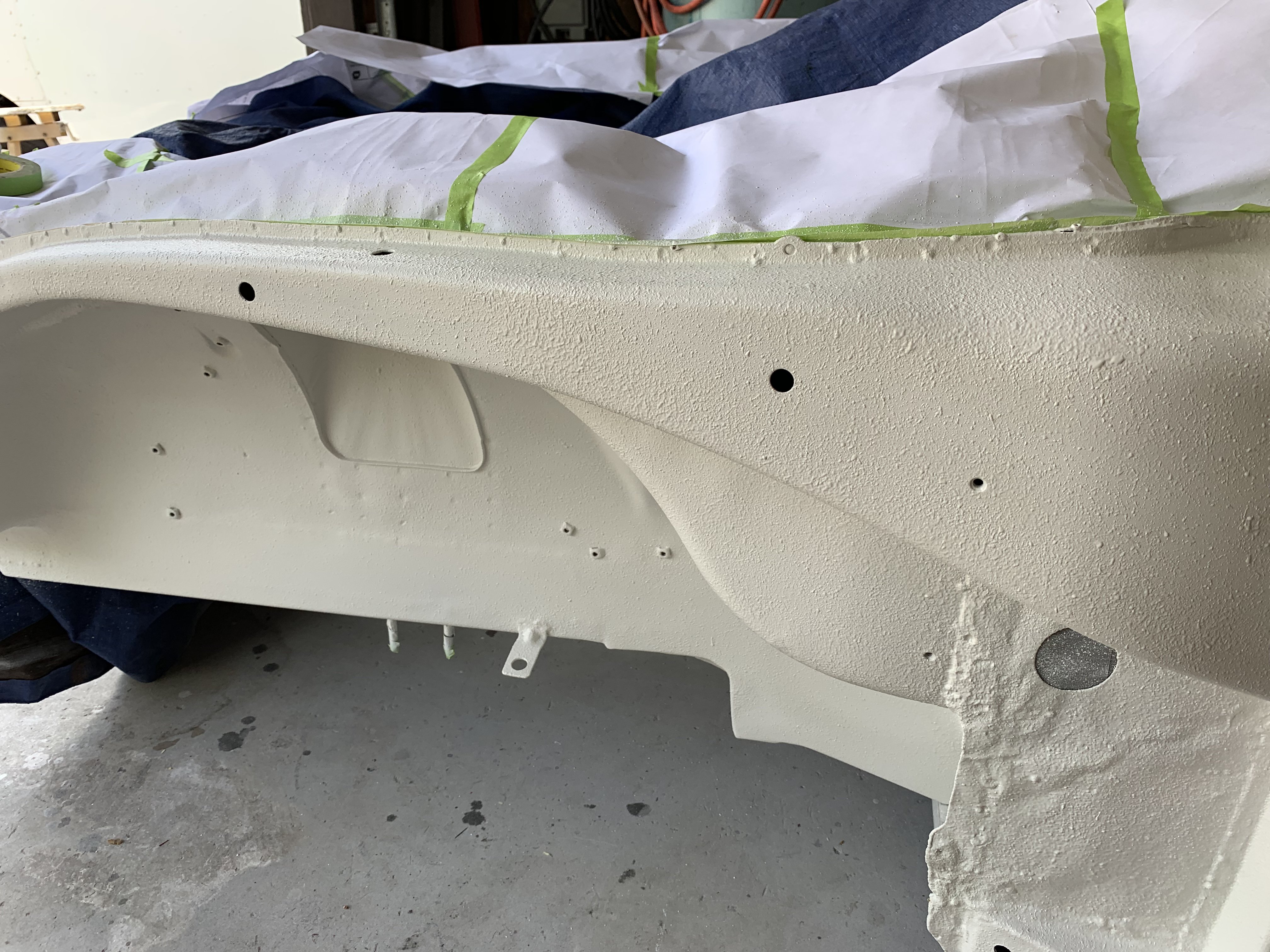
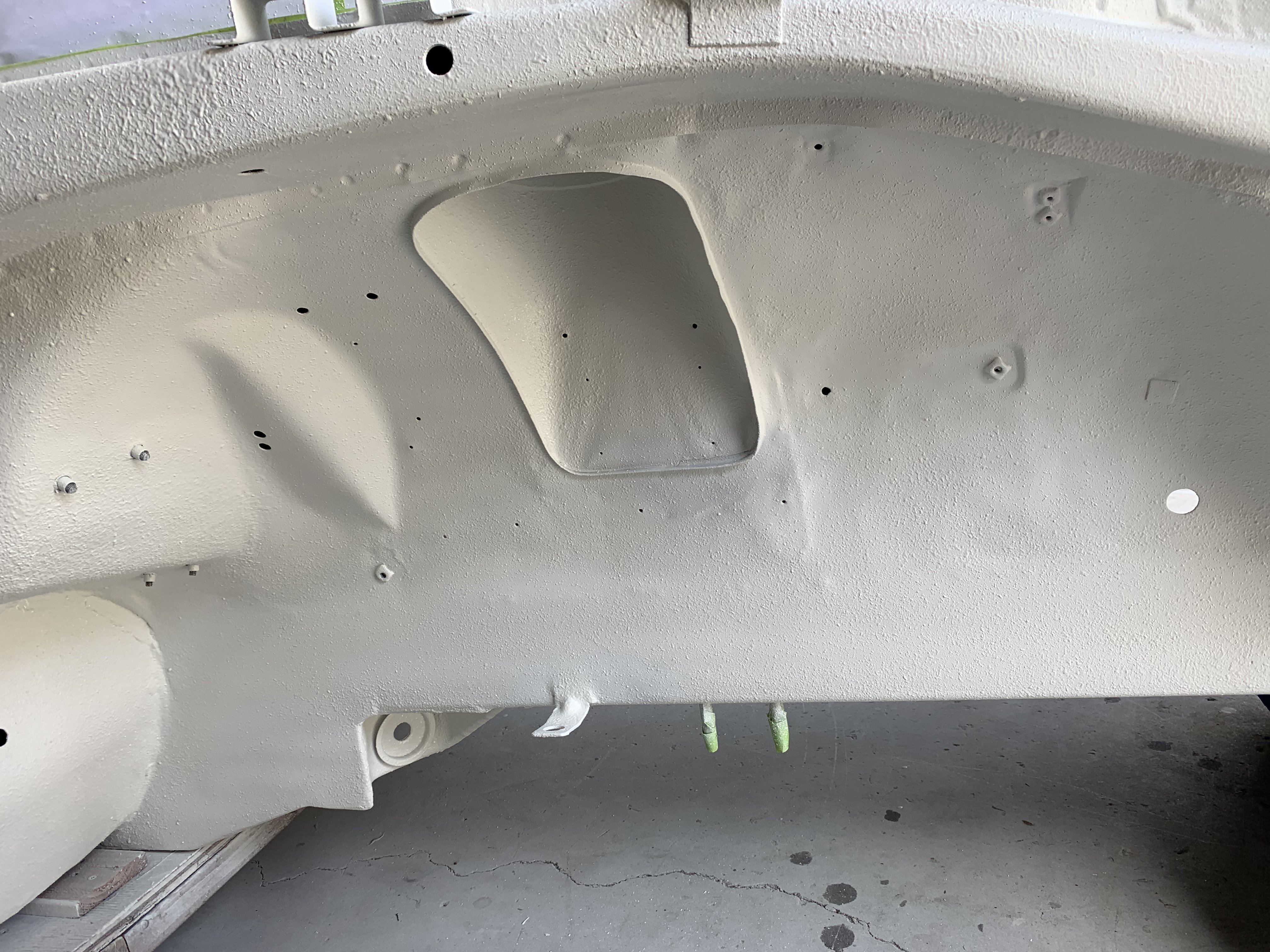
Back home to get working on the Z. From Epoxy Primer to Body Filler. Body Filler used to cover minor imperfections. Sanding Body Filler Then paining Polyurethane Primer Sealer on top of that bodywork. Not to forget the inside of the front fenders, the sealing of them was next thing to do. The wheel well deflector plate stripped and painted. I decided to use rubber weather stripping. I found 3M "D" shaped weather stripping on Ebay for $13 for 8 feet. The hollow inside made very soft and a good weather stripping for the wheel well. front view back view Previously I had planned to use Dynamat or similar foil type of insulation for the floor and roof. However, I decided to use Lizard Skin Ceramic Insulation paint. It can lower the interior temperature 20 to 30 degrees. One gallon costs $100 on Amazon. They also sell sound insulation paint(costs $100 gal) but it must be applied first(before heat insulation). Had planned to spray it on with a Schulz under coating gun but the coating was too thick for the gun. So I used rollers and a brush to apply it. A cordless drill was utilized to stir the paint. Use low speed and in Reverse so the particles are not damaged while mixing. Application was done in two .020 coats allowing the first coat to dry to the touch. Curing will take possible a week to completely cure depending on weather conditions. All holes must be masked off to prevent over spray. Areas to be painted are scuff sanded and all threaded holes are plugged. After painting Ceramic Coating was not difficult to apply. Cleanup should be done quickly as the insulation dries relatively fast. Pic of roof coated Pic of seat area Passenger side compartment After the Ceramic Insulation is cured, I will probably top coat it with Polyurethane White Single Stage Paint for added protection.
-
Heavy Duty frame rails and connectors
toolman replied to toolman's topic in Gen III & IV Chevy V8Z Tech Board
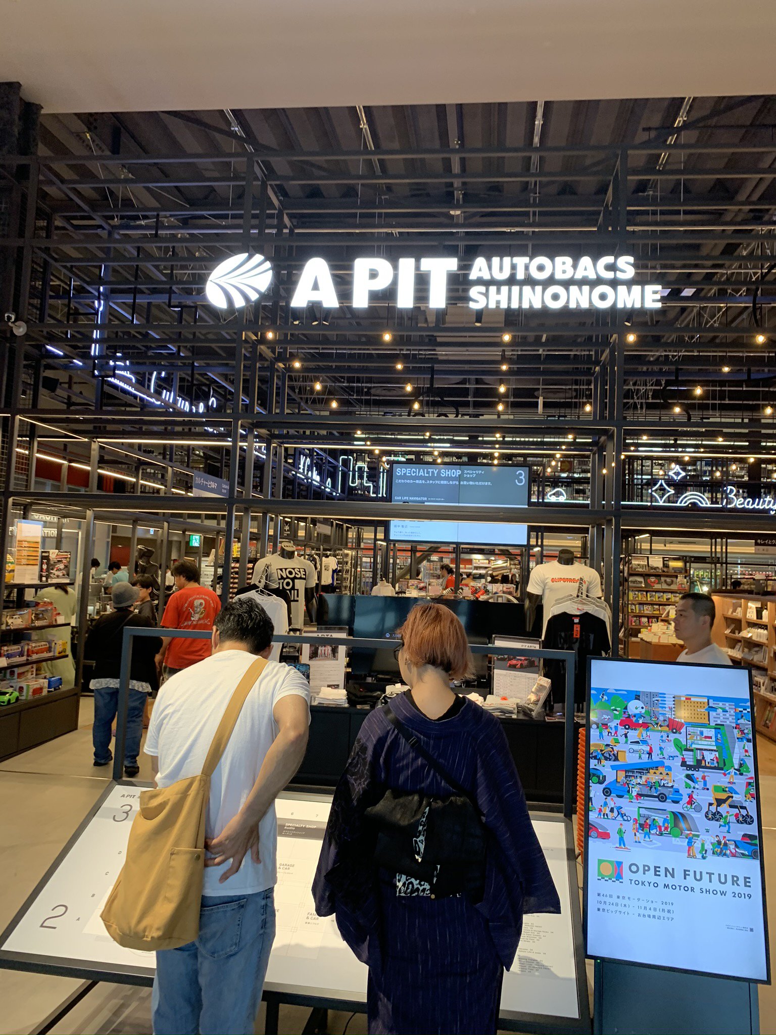
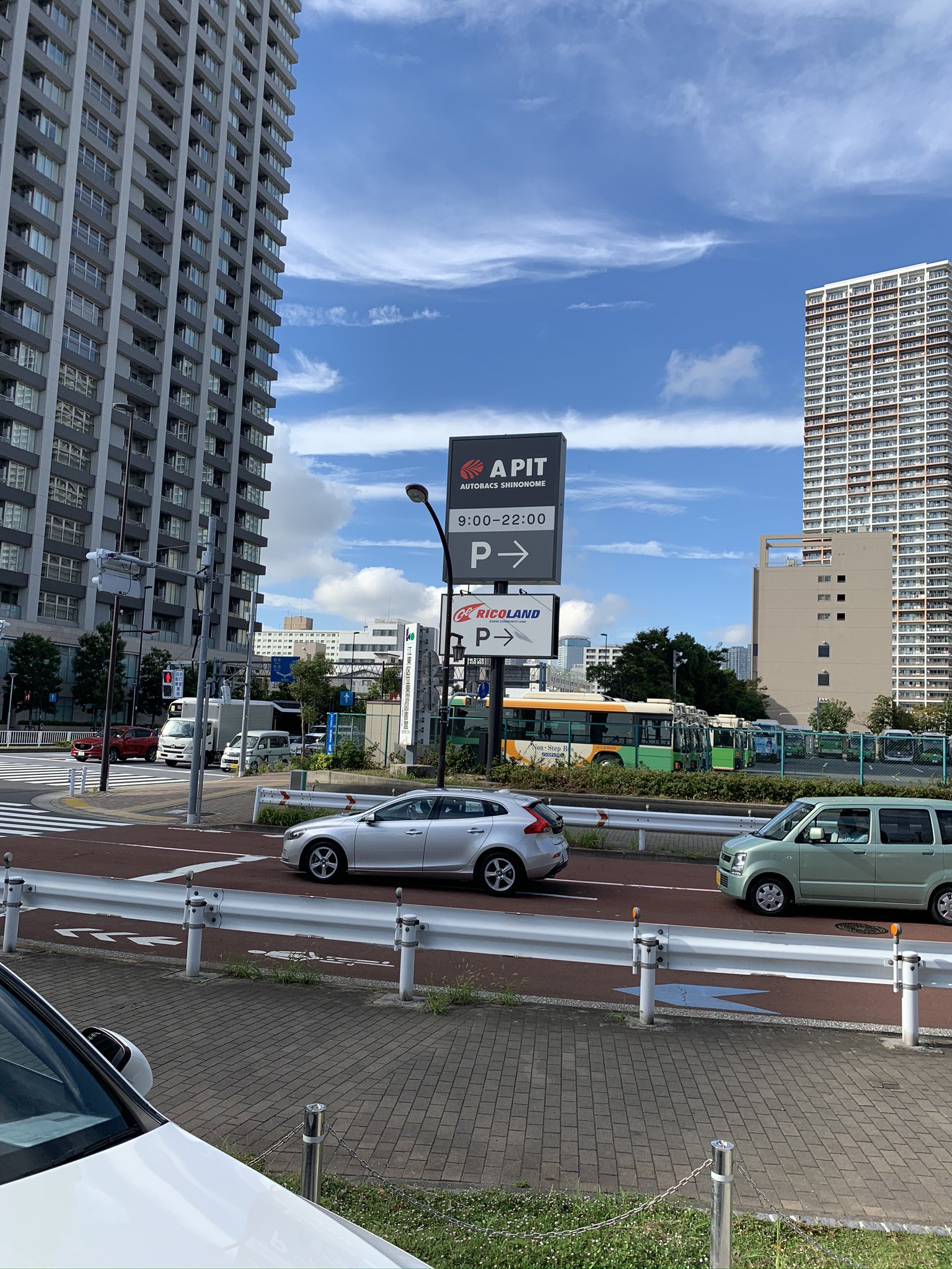
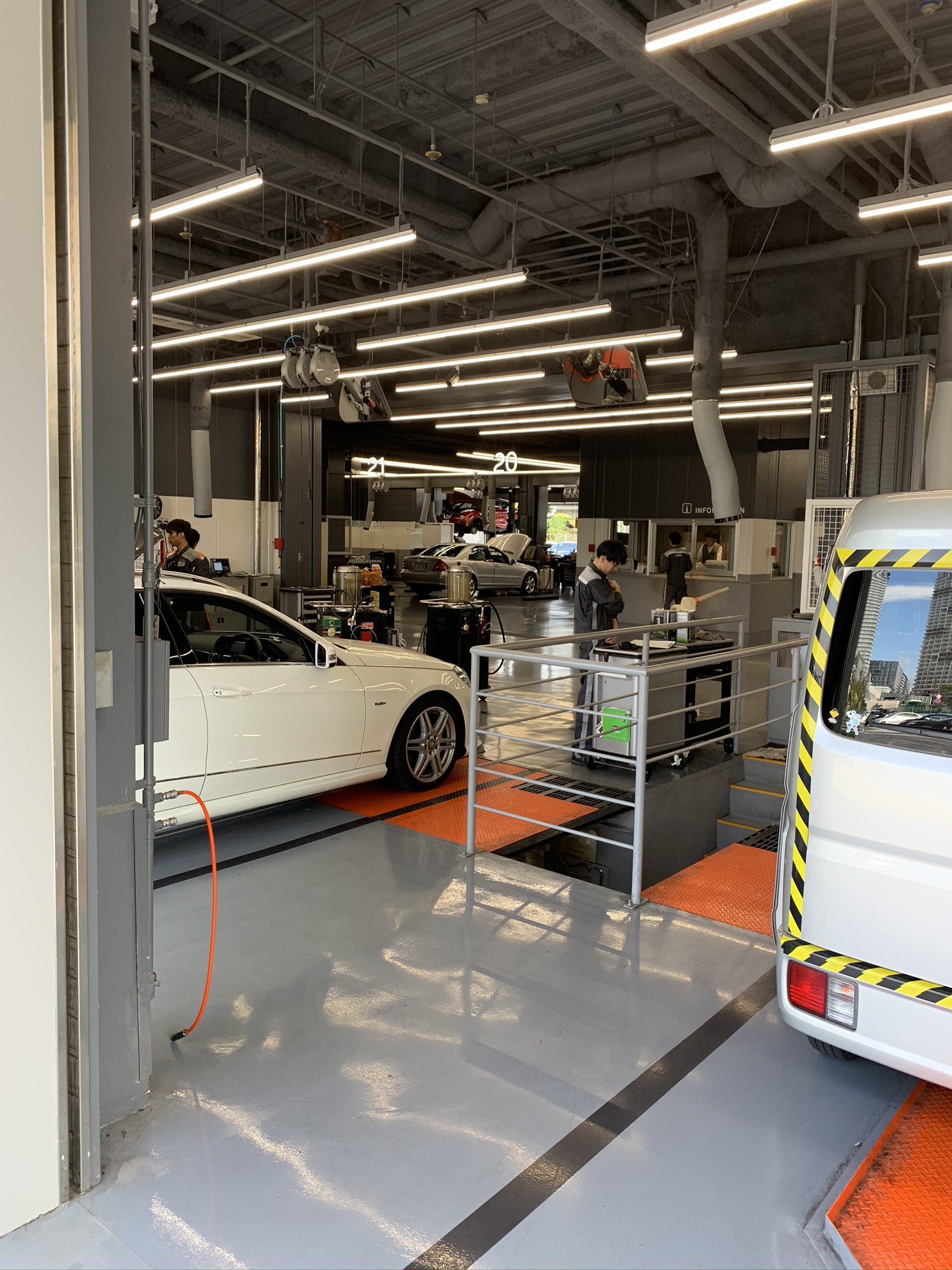
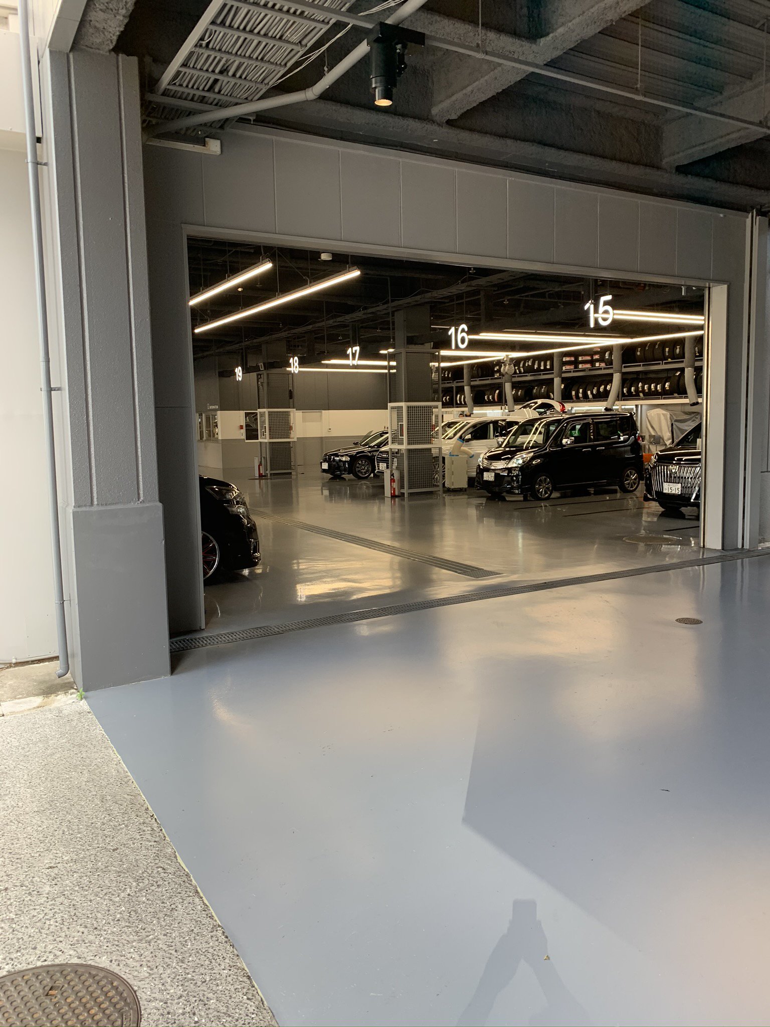
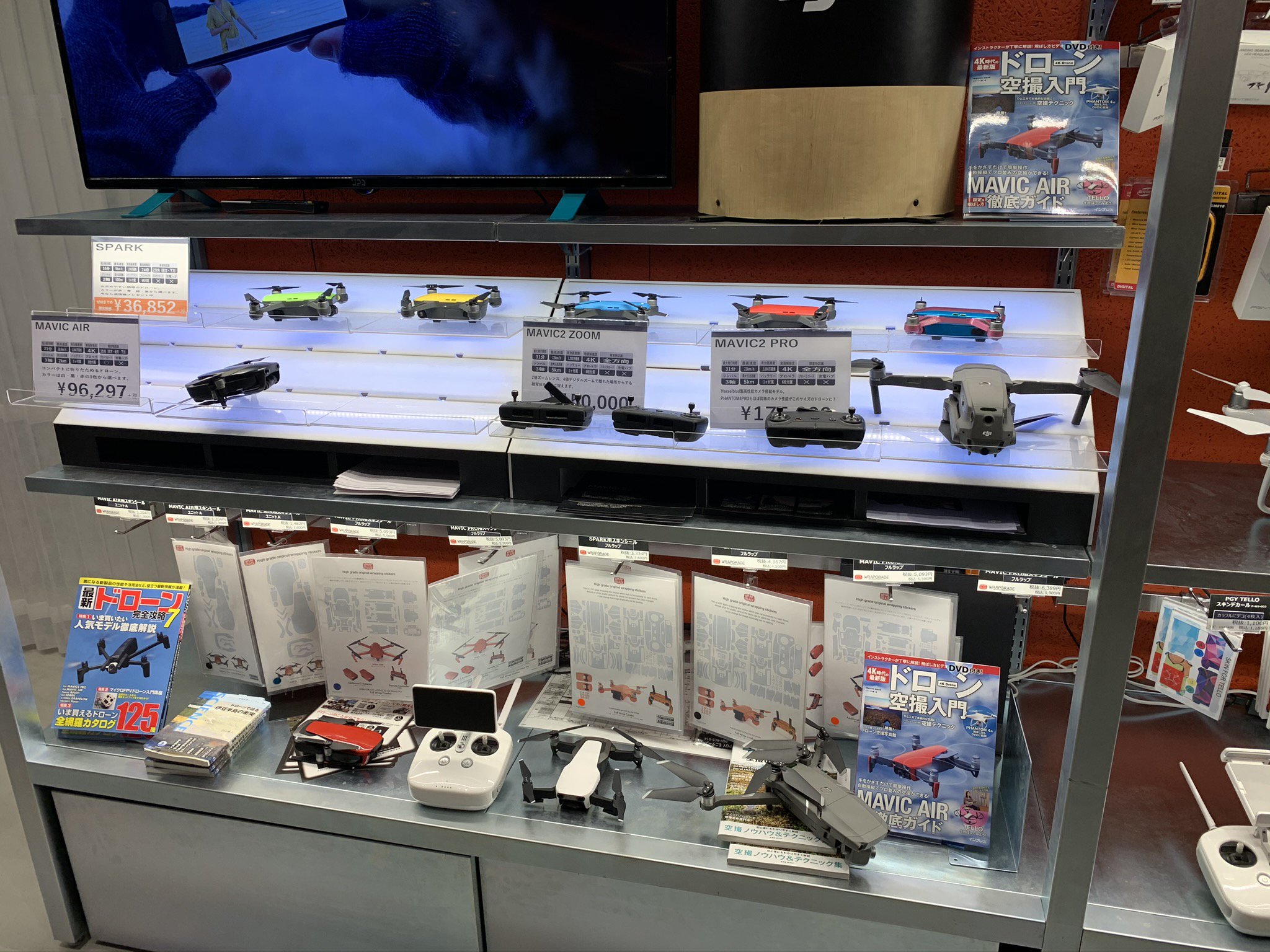
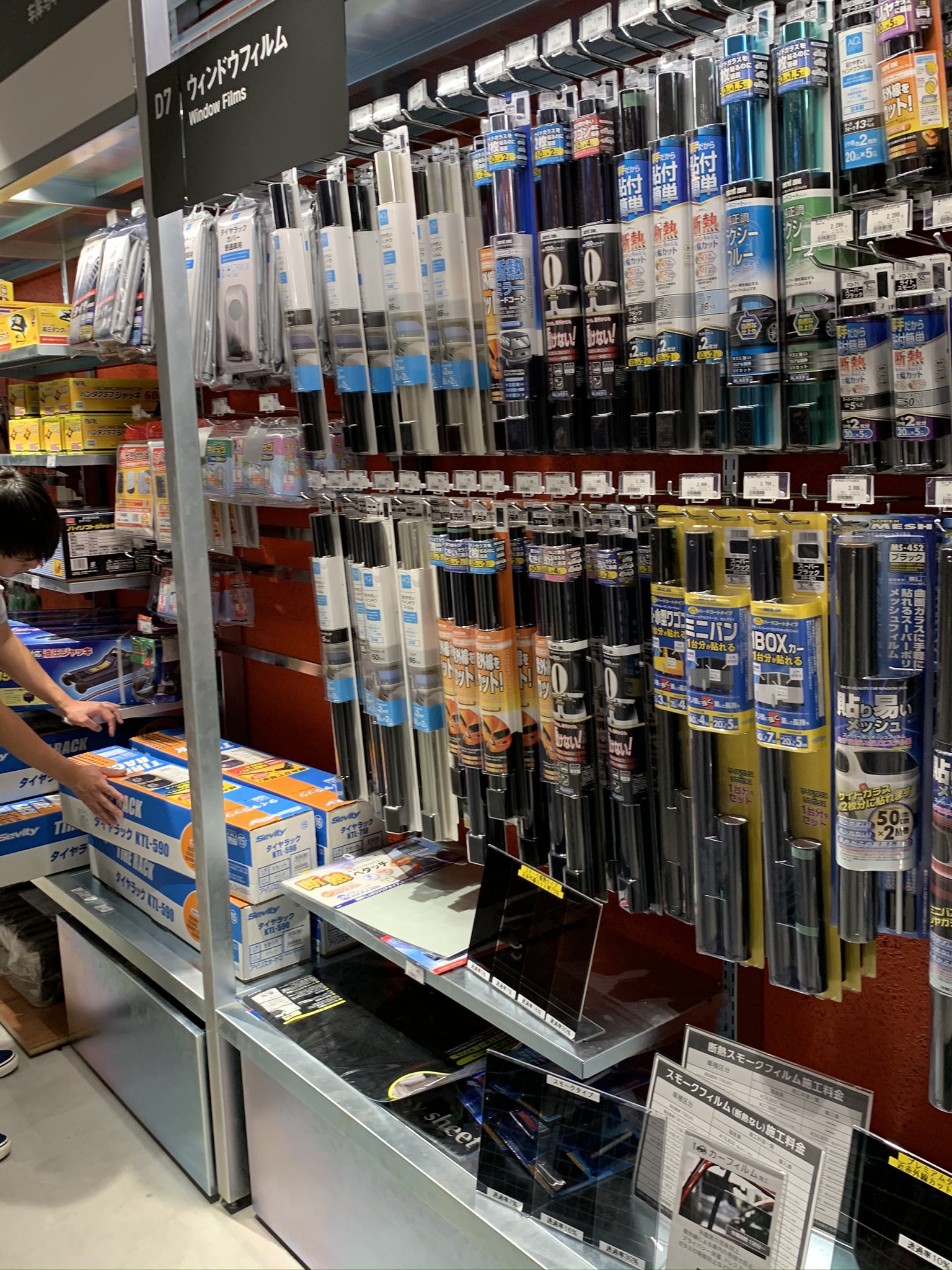
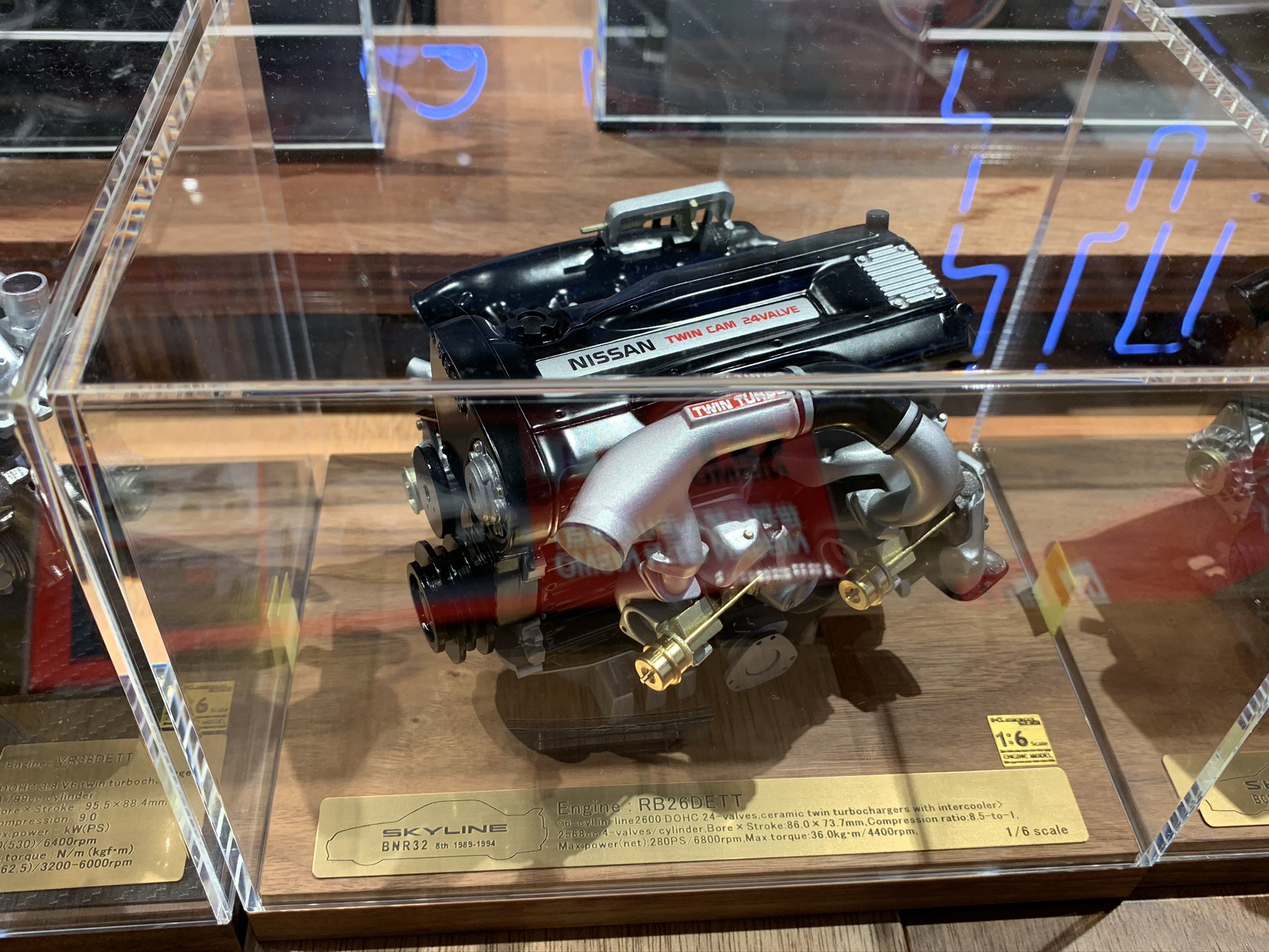
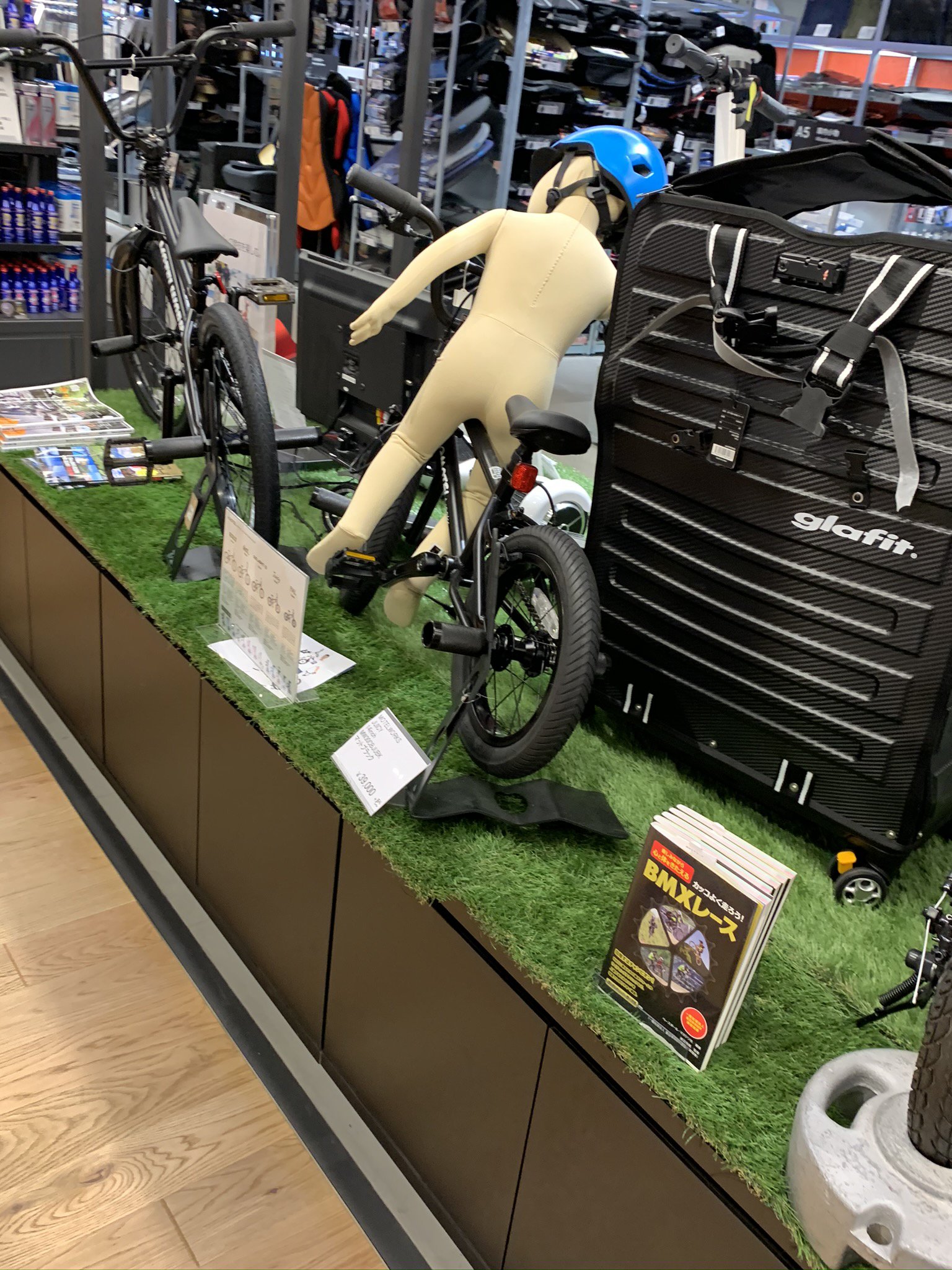
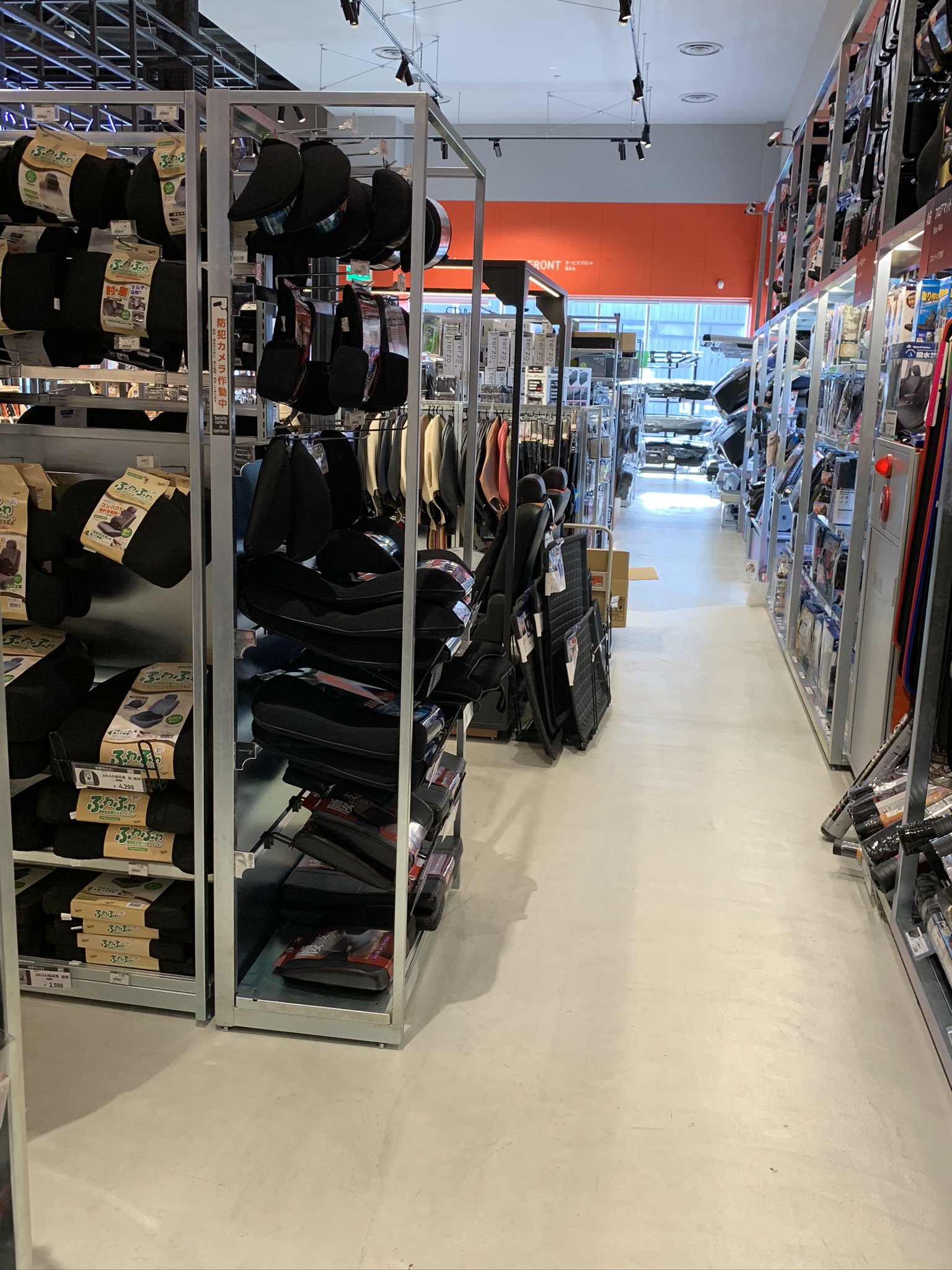
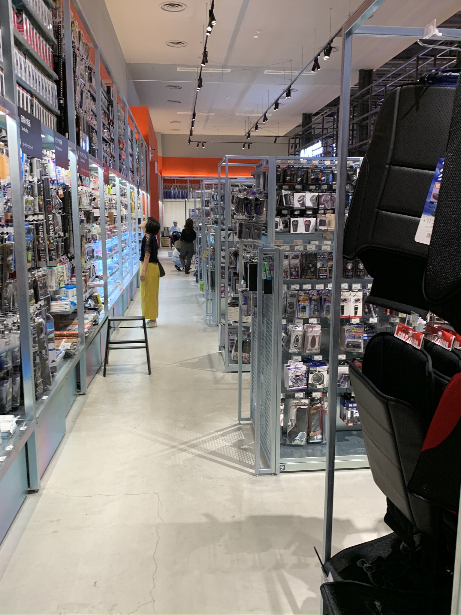
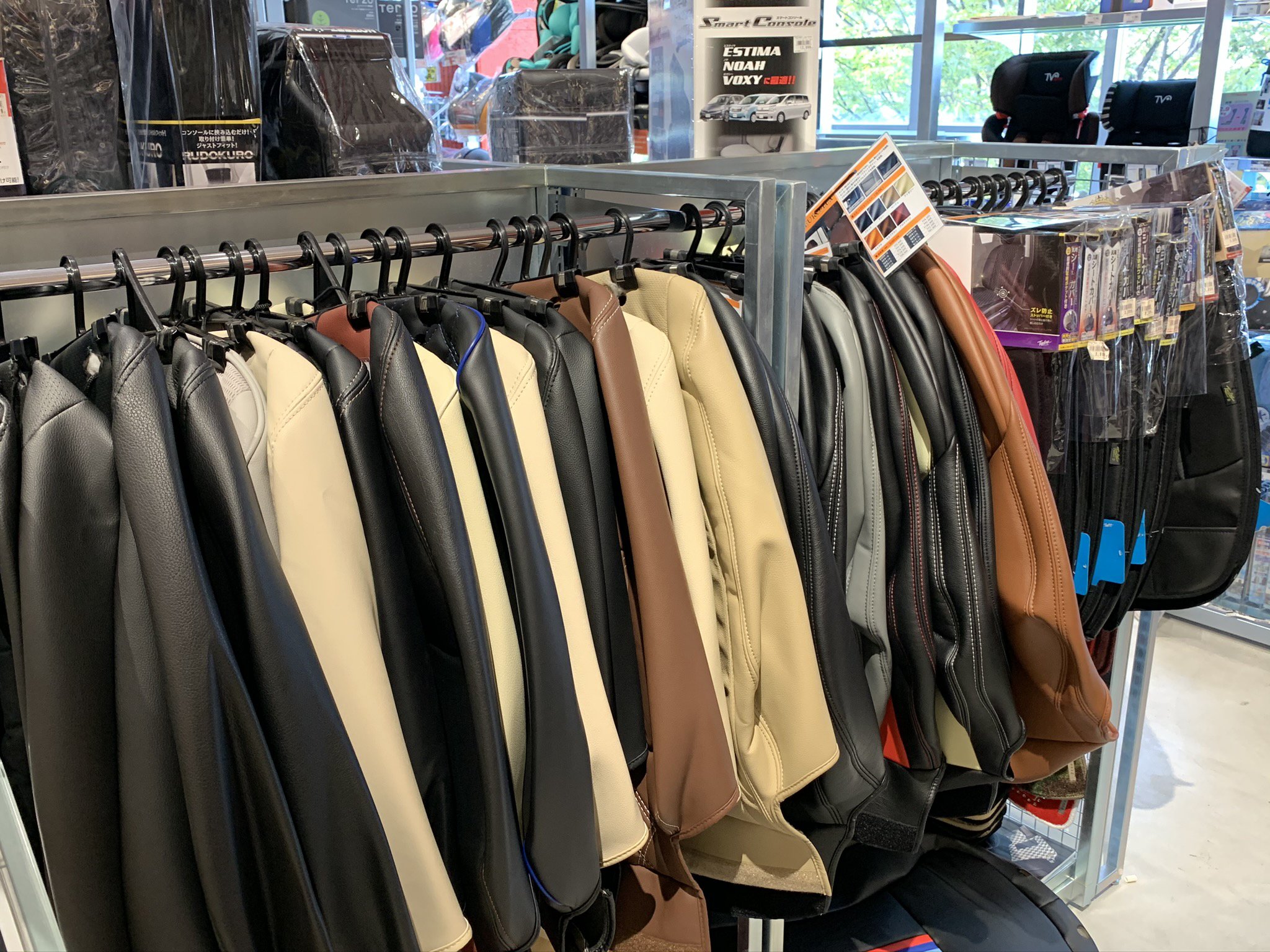
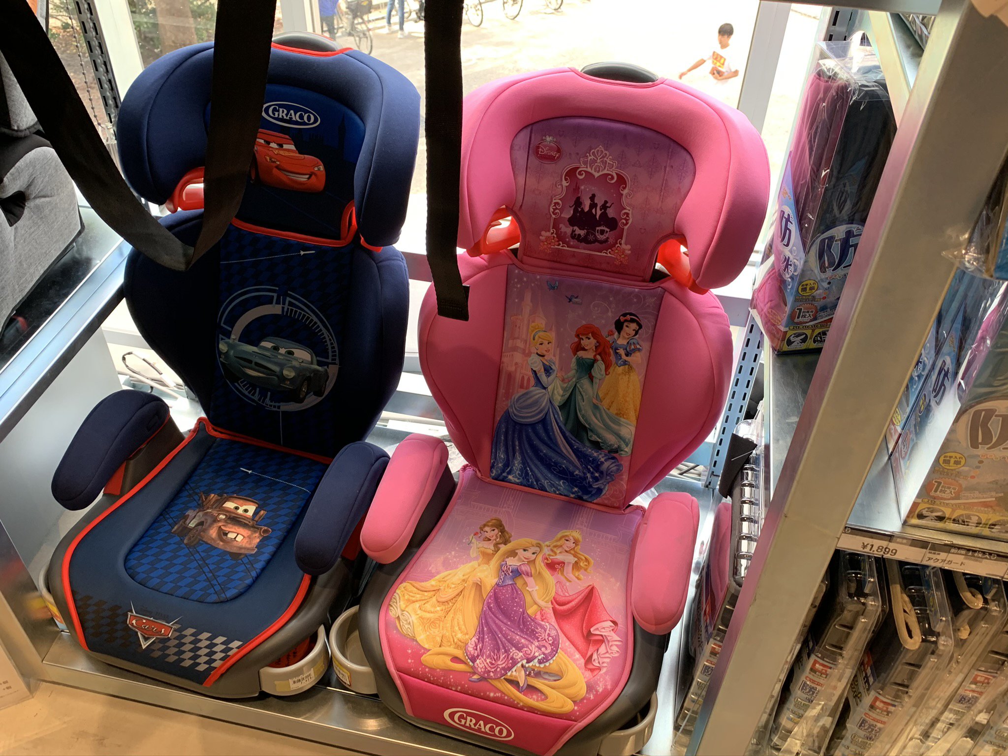
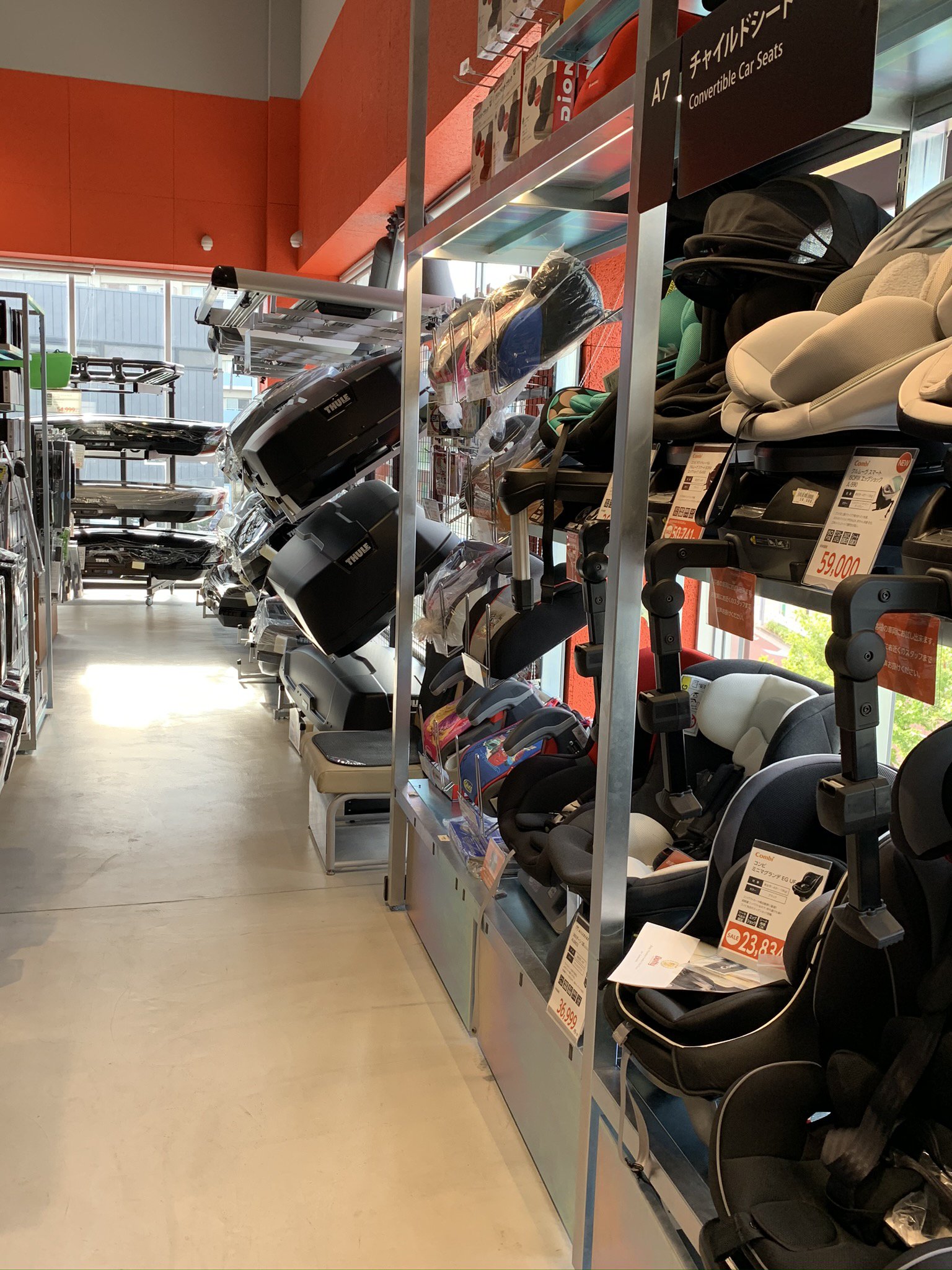
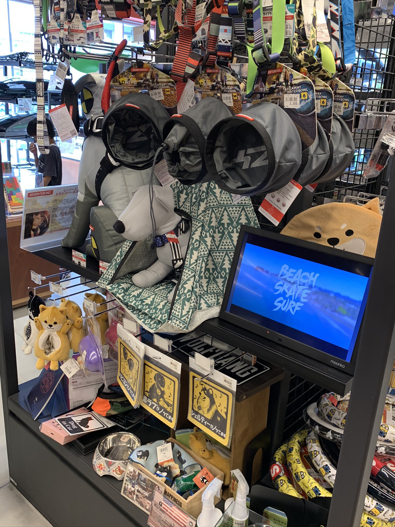
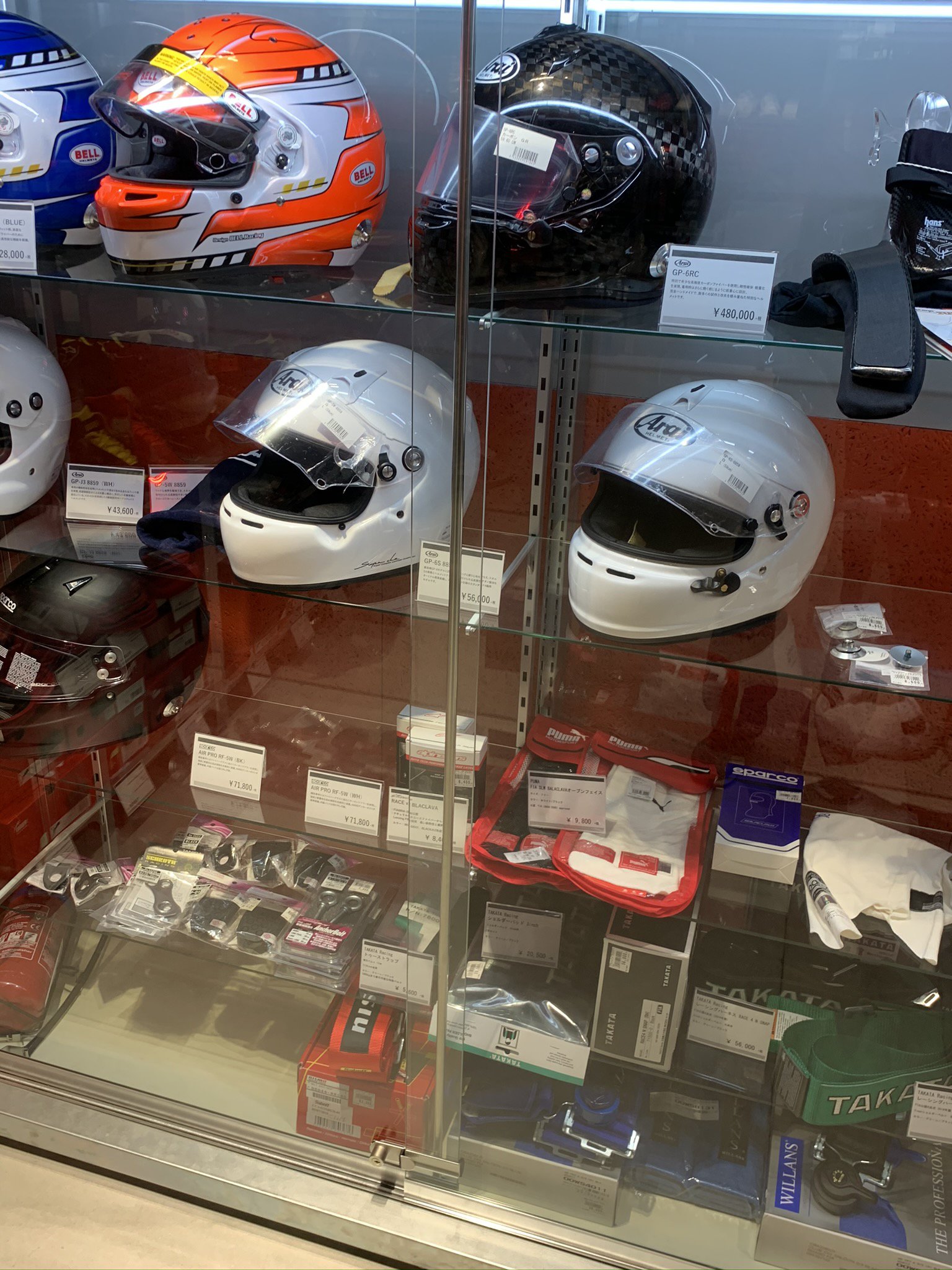
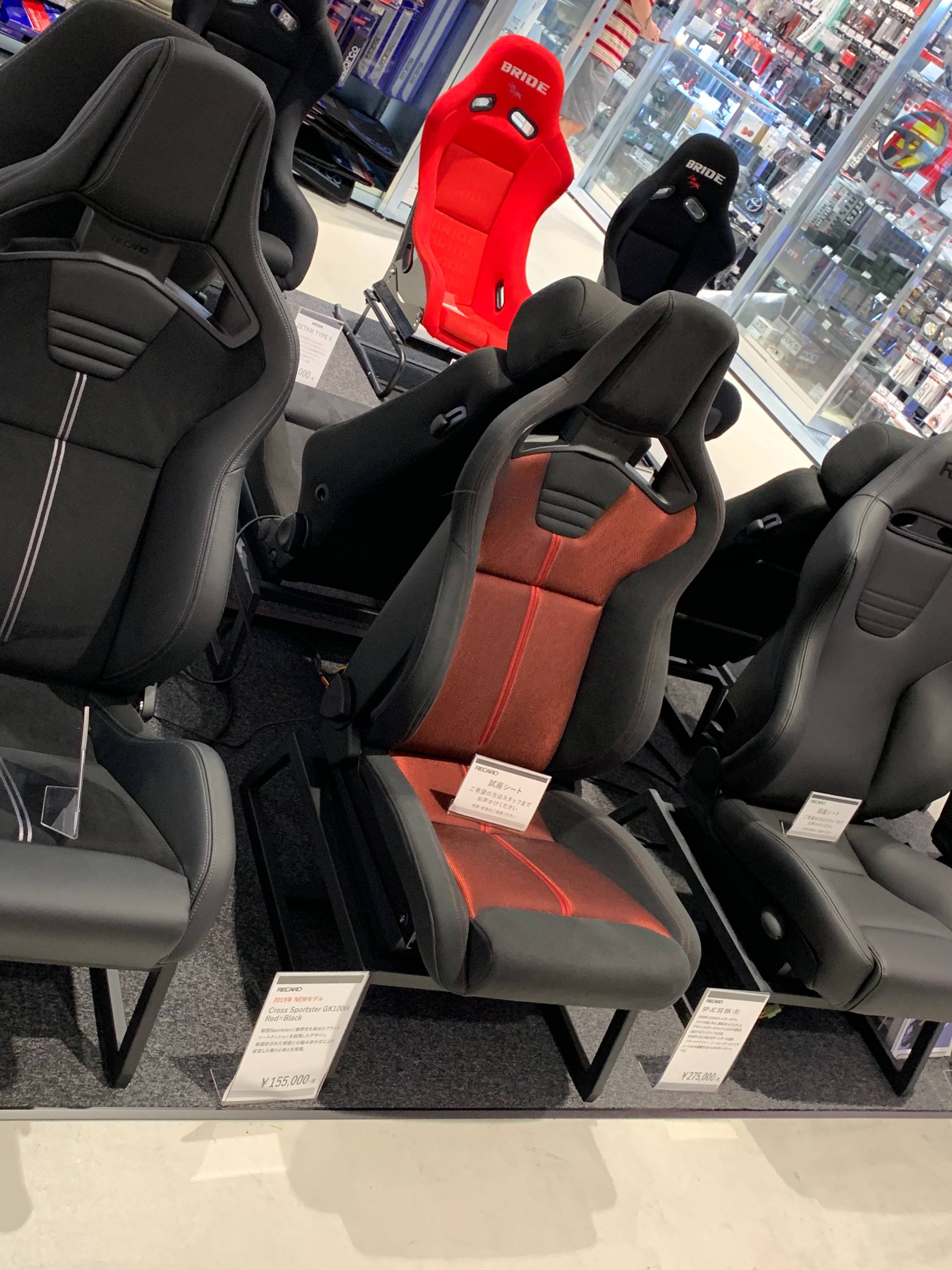
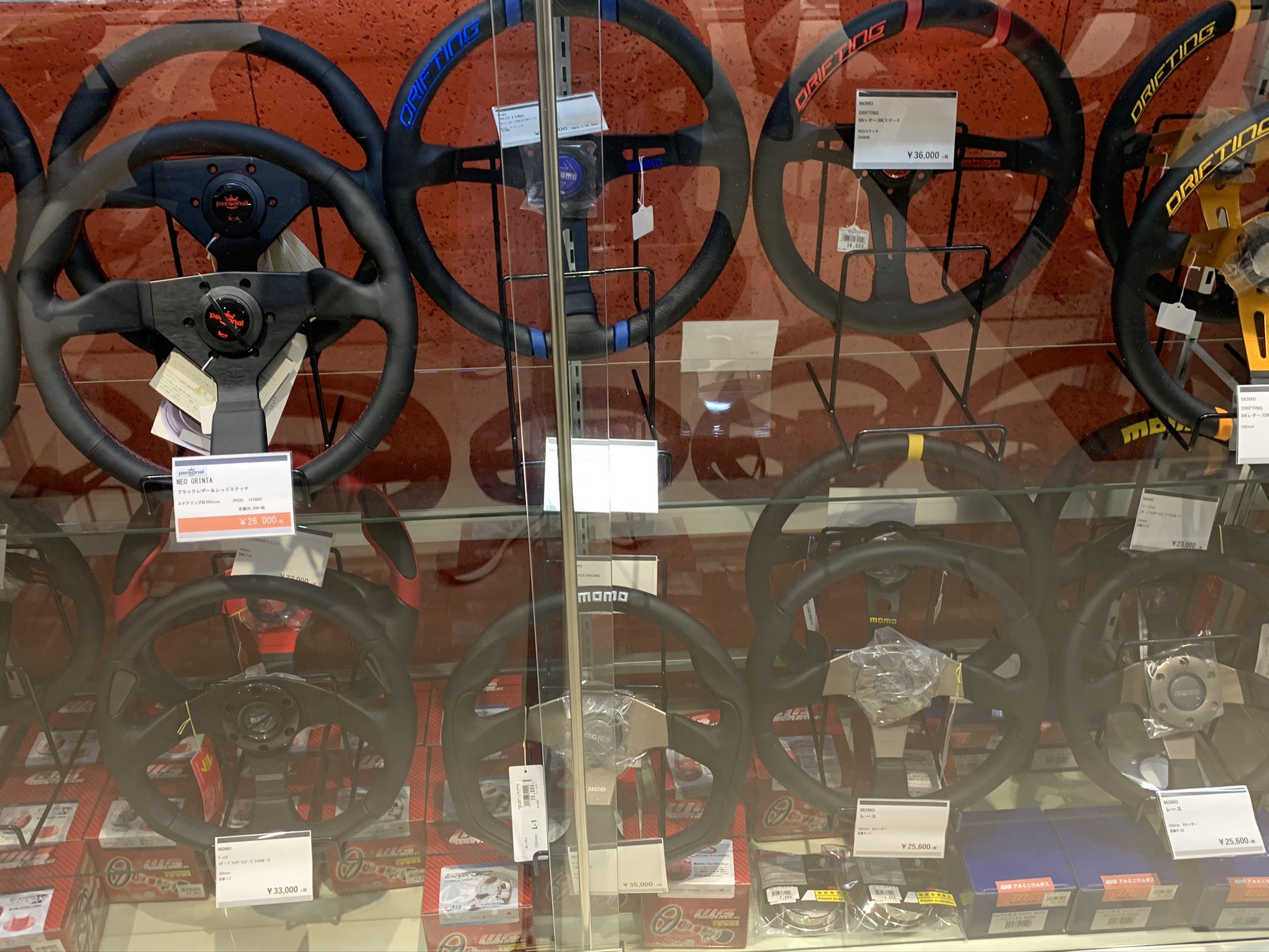
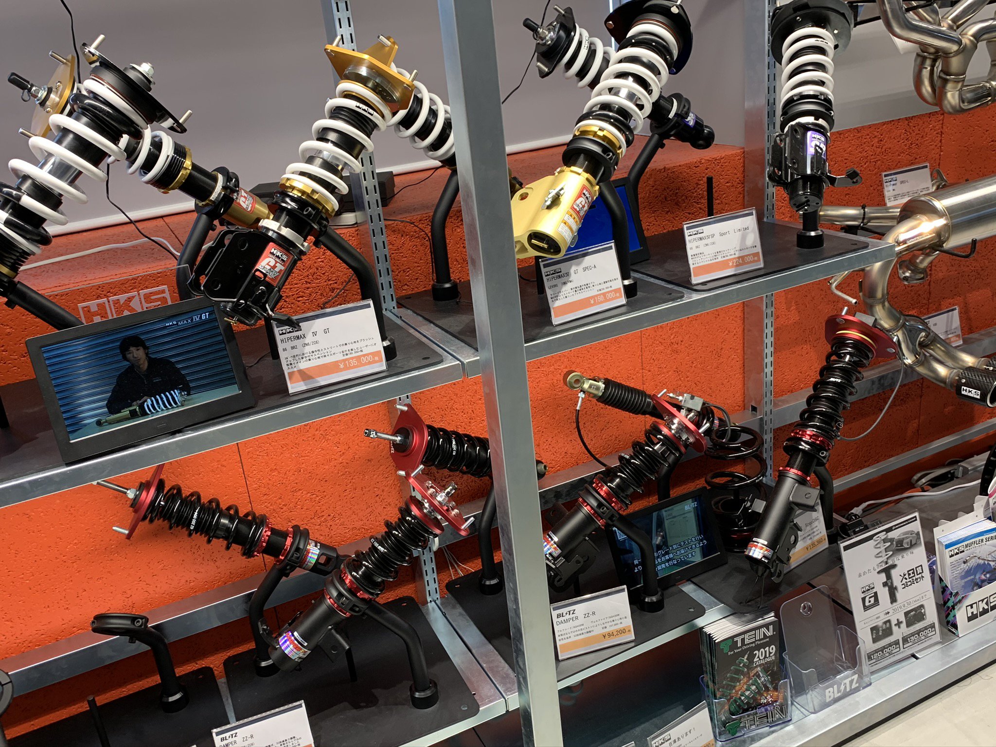
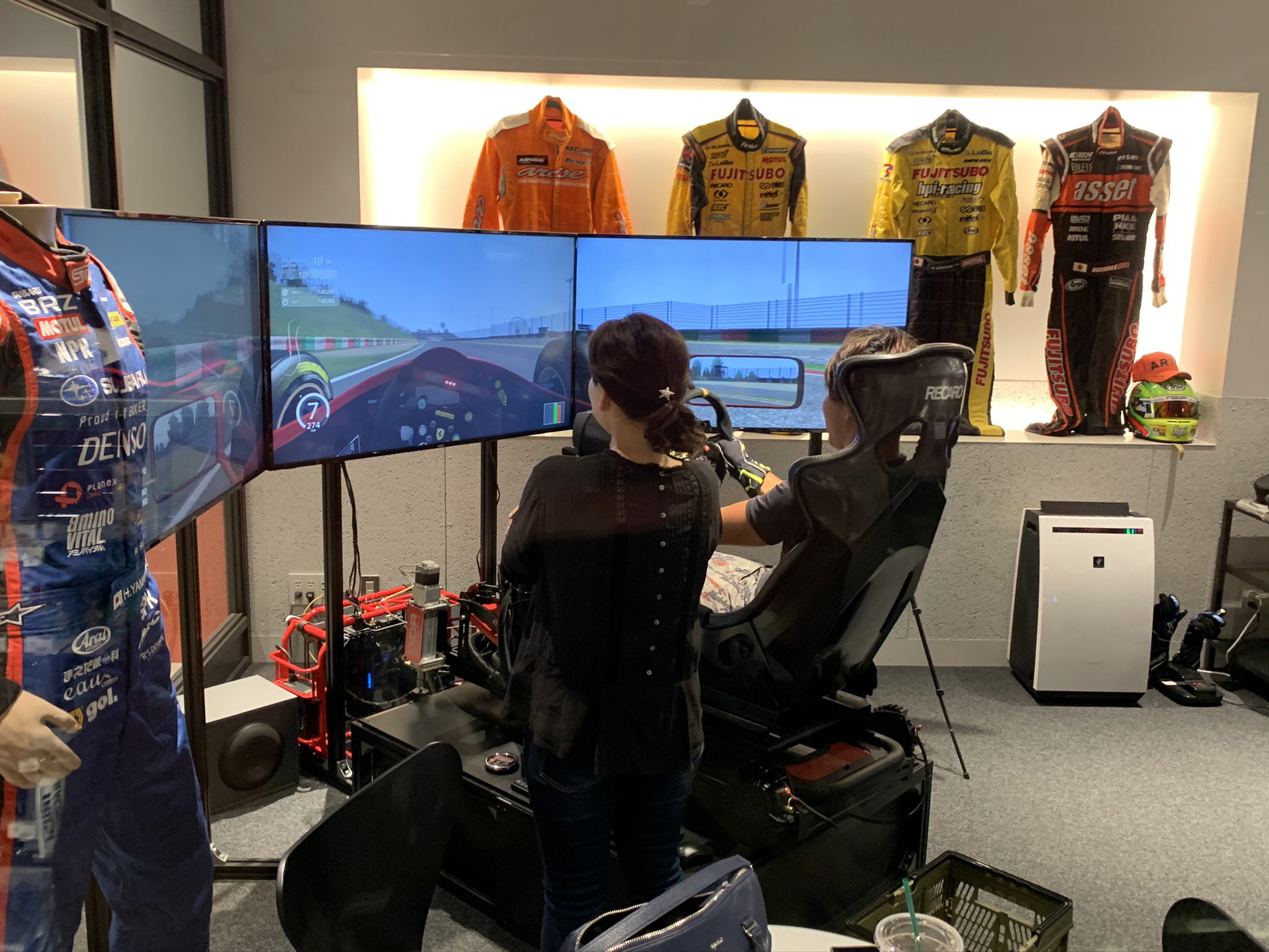
I just got back from Tokyo. I managed to go Japan's Largest Automotive Store in Japan Autobacs Shinome located near Tokyo Bay. The garage is on the bottom of this three level store. The main store is on the Second floor and has a coffee shop there. the third floor is the high performance stuff. Snap On tools on display in glass cases. Snap On Tools tools sell for twice the US price. That Snap On tiny tool box toy sells for $140!! Snap Tools on display. On the third floor, the high performance parts and accessories were on display. They had the latest GPS., stereo ,DVD, and LED lights. And, of coarse, the garage downstairs could install whatever you purchase. Helmets, gloves and gear. the Black one cost about $5600 USD Steering wheels (Momo one was $300 USD. Racing suspension parts-NHW strut was $1350 USD There was a rear driving simulator that anyone could try for a price. It had loud speakers 3 TV screens and air shocks to give the real.feeling of a race car. I think the price was $50 for 30 minutes. Unfortunately, I found about the simulator too later as I had to get back to Shinjuku before the afternoon rush on the trains. Passengers are really packed like sardines during rush hour!!!!! The store is located near Odiba theme park by Tokyo Bay near Tokyo Disneyland. Front Entrance of the store The Garage Area is Super Clean and well lite. Mechanics even wear white gloves when working. Only High End Wheels no China Stuff here. !/6 scale Skyline motor very detailed. Bicycle and accessories Aisles of assorted stuff There is a large area with only automotive books and magazines next to their coffee shop. Everthing automotive under the Sun is here. Leather jackets Kids $500 electric cars. Kids seats more seats and seat covers $1000 Mavics RC Drones This Skyline motor sells for $300 but is well detailed. wiper blades Pet accessories Snap On floor jacks-the silver one sells for$200(about $100 in US) Can't wait to start back to working on my Z. SEMA SHOW 2019 is less than a month away. Viva Las Vegas!!
-
Heavy Duty frame rails and connectors
toolman replied to toolman's topic in Gen III & IV Chevy V8Z Tech Board
The door hinges for both Left and Right sides were top coated with Polyurethane paint. Shop Tip- Removing and Installing a 240Z hood by yourself Place a Plywood on top of the Left and Right fenders. Put hood in the closed position. Put card board or padded mat under plywood to prevent scratching the paint. Raise hood to open position. Loosen all four hood bolts but do not remove. Remove both hood front bolts. Now tilt the rear of the hood downward till the hood contacts the plywood. Then remove the rear hood bolts as the hinge and plywood will support the weight of the hood. The hood can be lifted off from either side of the car. Hood installation will be the reverse procedure. The next thing to do to spraying Raptor Liner in the fender and wheel wells. This Raptor liner was the 2 bottle kit with Liner, hardener and color toner.. This kit costs about $100 including freight on Ebay. Masking the hood to prevent overspray going all over the place. The interior sides of the hood and fenders were sanded with 150 grit sand paper then wipe down with paint prep solution. view of Left side Wheel Well Housing afterspraying. Right side Wheel Well Housing after spraying Liner Right side fender interior view Inside Right Door view Closeup view of the Raptor Liner on Wheel Hosing Inside Right Fender Note- Liner even covers patch area. Left side Wheel Well Housing The Raptor Liner can be applied by hand roller or sprayed. A Schutz gun is most commonly used to apply the liner. HLVP spray gun with 2.0 nozzle can be used if liner is reduced by 20%. This method would provide a smoother finish( not as rough}. After one hour, the liner is dry to touch. It, however. takes a full week to completely cure. I used only one bottle of Raptor Liner so far. The remaining bottle will be used for the rear wheel housing after I finish flare modifications.
-
Heavy Duty frame rails and connectors
toolman replied to toolman's topic in Gen III & IV Chevy V8Z Tech Board
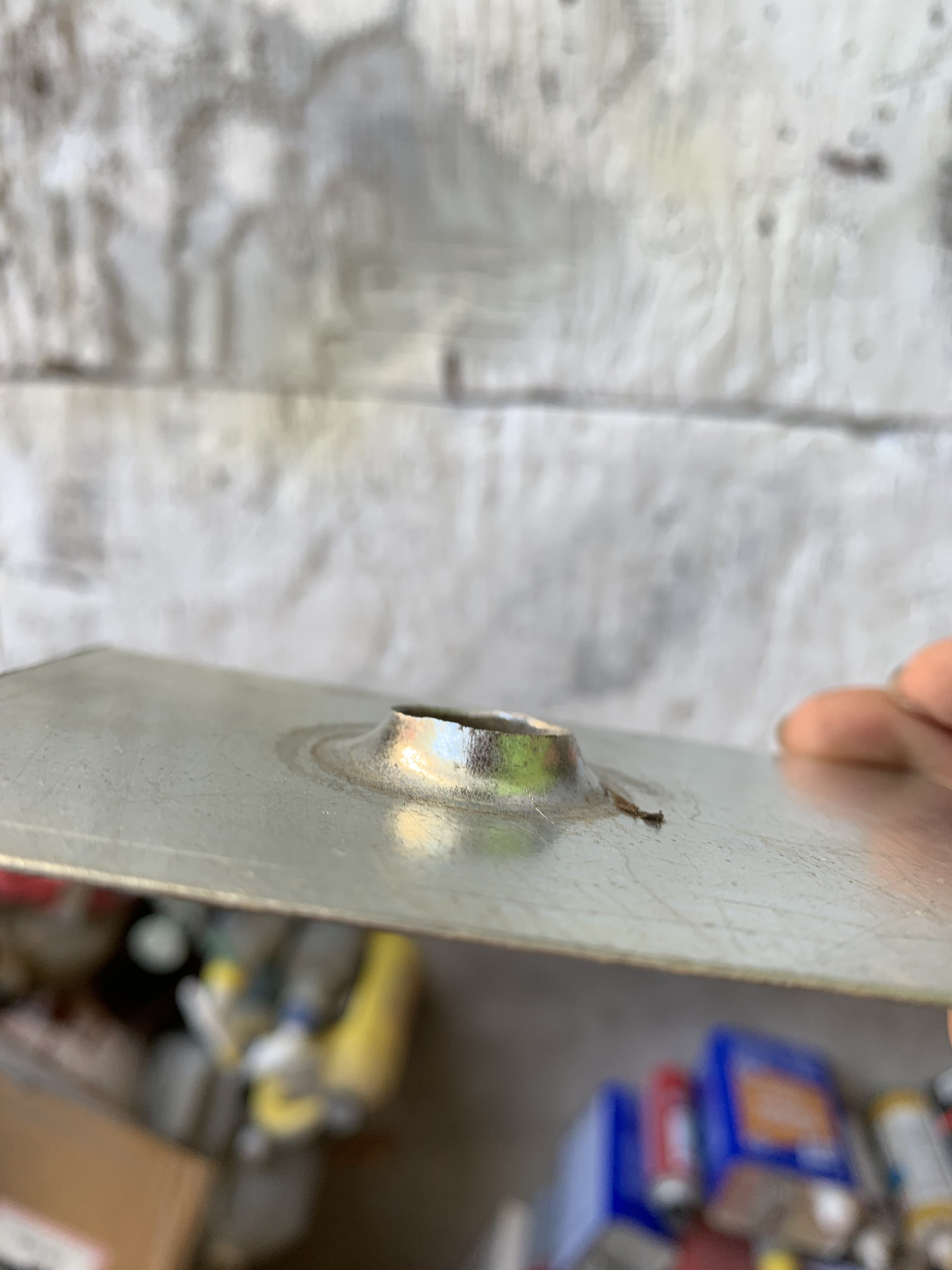
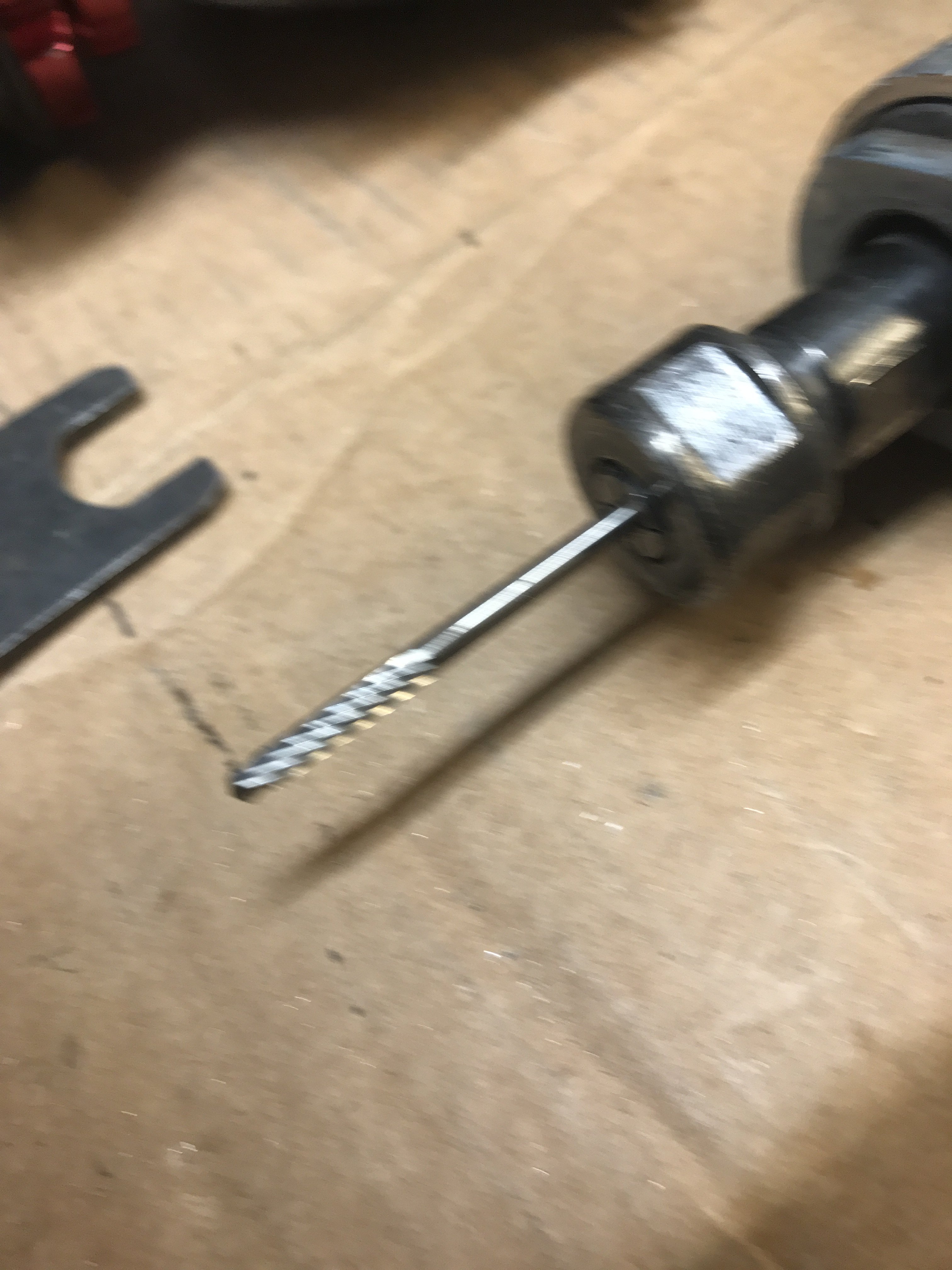
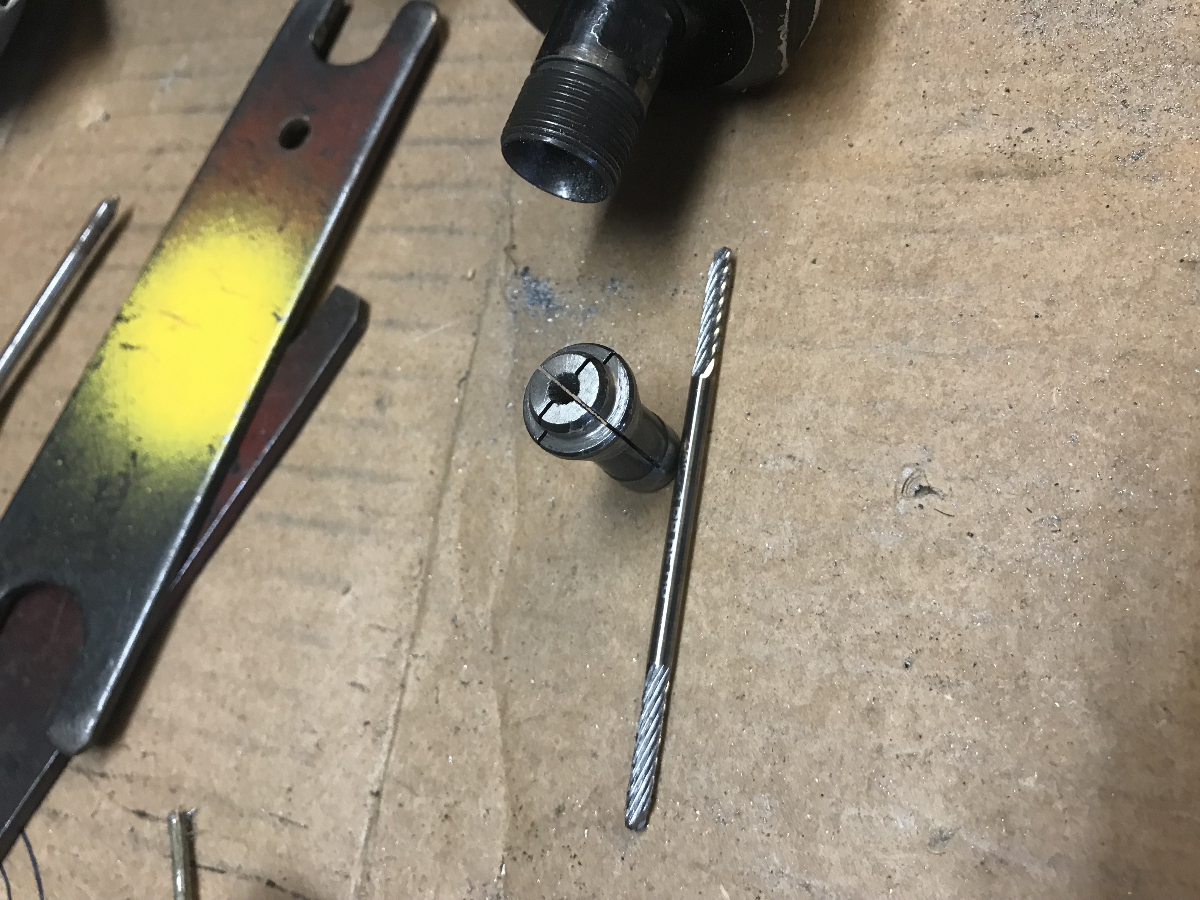
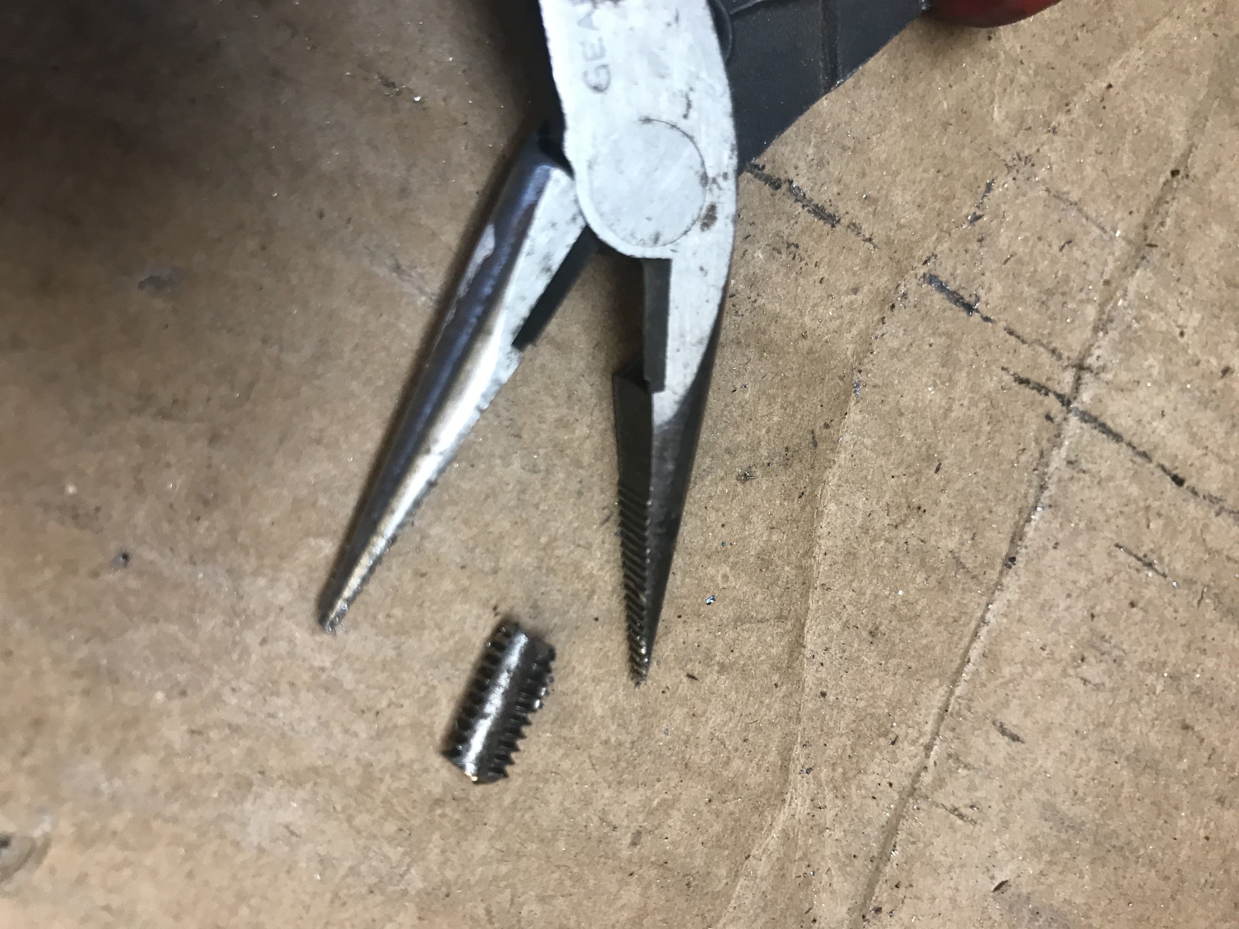
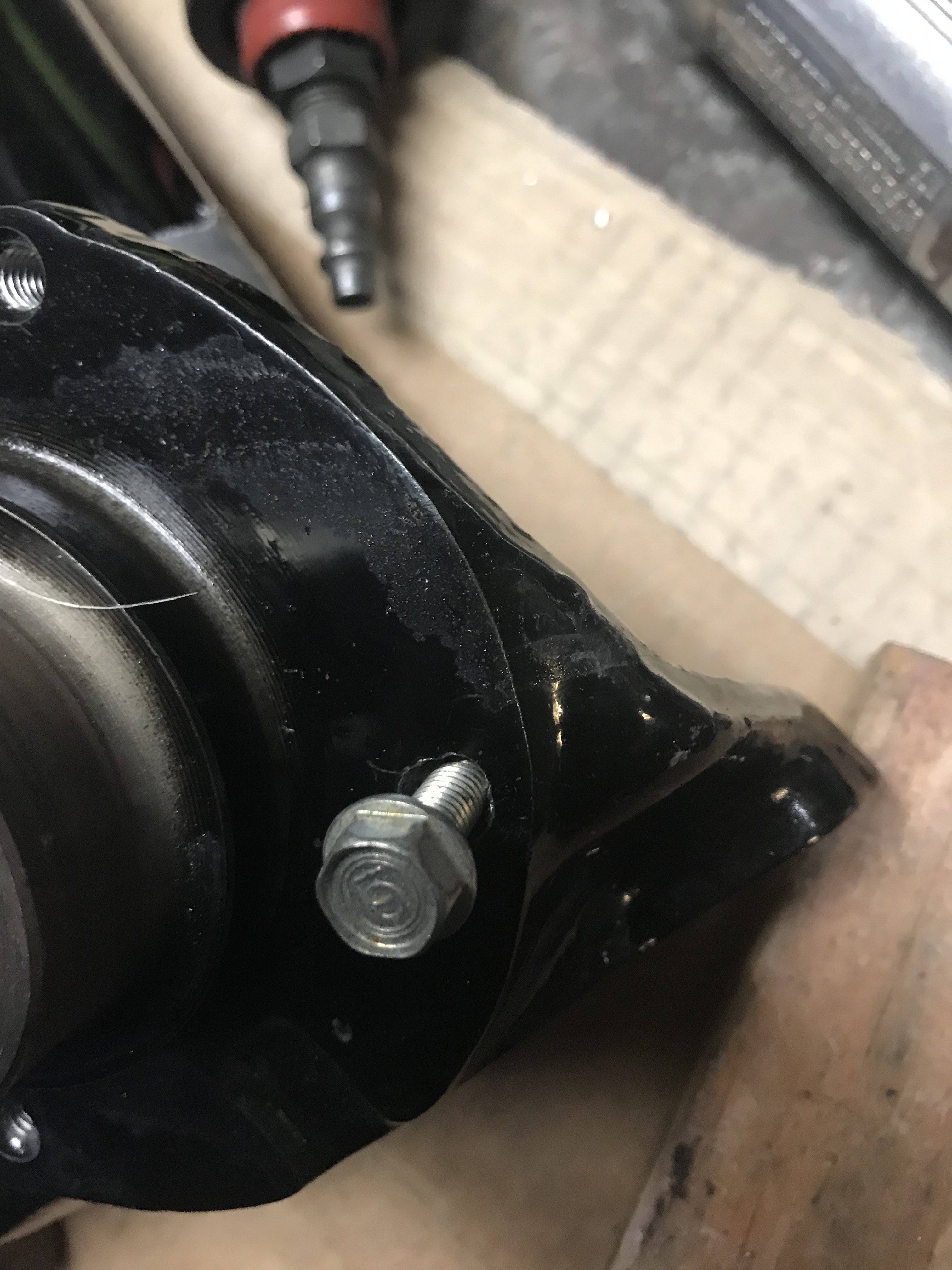
PROJECT TIP: I am posting this tip as it may be very helpful to a lot of people. RESCUE BIT is a high speed cutting bit that will cut through broken taps, extractors just about anything. Check the video out at https://www.youtube.com/watch?v=FkIH7DhQJzA In my case, I was tapping out the bolt holes of my struts. Of course, while tapping the last bolt hole, the 6mm x 1.0 tap broke. Pic of the Broken tap This is a picture of a 1/8" RESCUE BIT with cutting edge on both sides. The 1/8" version must be used with a 1/8" adaptor to use it in a 1/4" die grinder. Pic of 1/8 to 1/4" adaptor. Rescue Bits also use to have 1/4" burrs (single and double cut version) too. Now the Rescue Bits can be found on Amazon and Ebay but only here and there. I don 't think the company still exists. I do keep one around for emergencies like this one. After drilling a hole in the center of the tap. I use a small sharp punch to collapse the walls of the tap inward. Here is one the larger pieces of the tap that was removed from the hole. After removing all remains of the tap, I carefully tapped the hole with a new 6 x 1.0mm tap. Success-bolt was threaded in!! It is important to carefully follow the instructions that come with the Rescue Bit. Also. the die grinder must be capable of 25,000 RPM. High speed and the bit design is what allows the Rescue Bit to do what other bits can not do. I hope some of you find this tip helpful. Rescue Bits costs about $60 online.
-
Heavy Duty frame rails and connectors
toolman replied to toolman's topic in Gen III & IV Chevy V8Z Tech Board
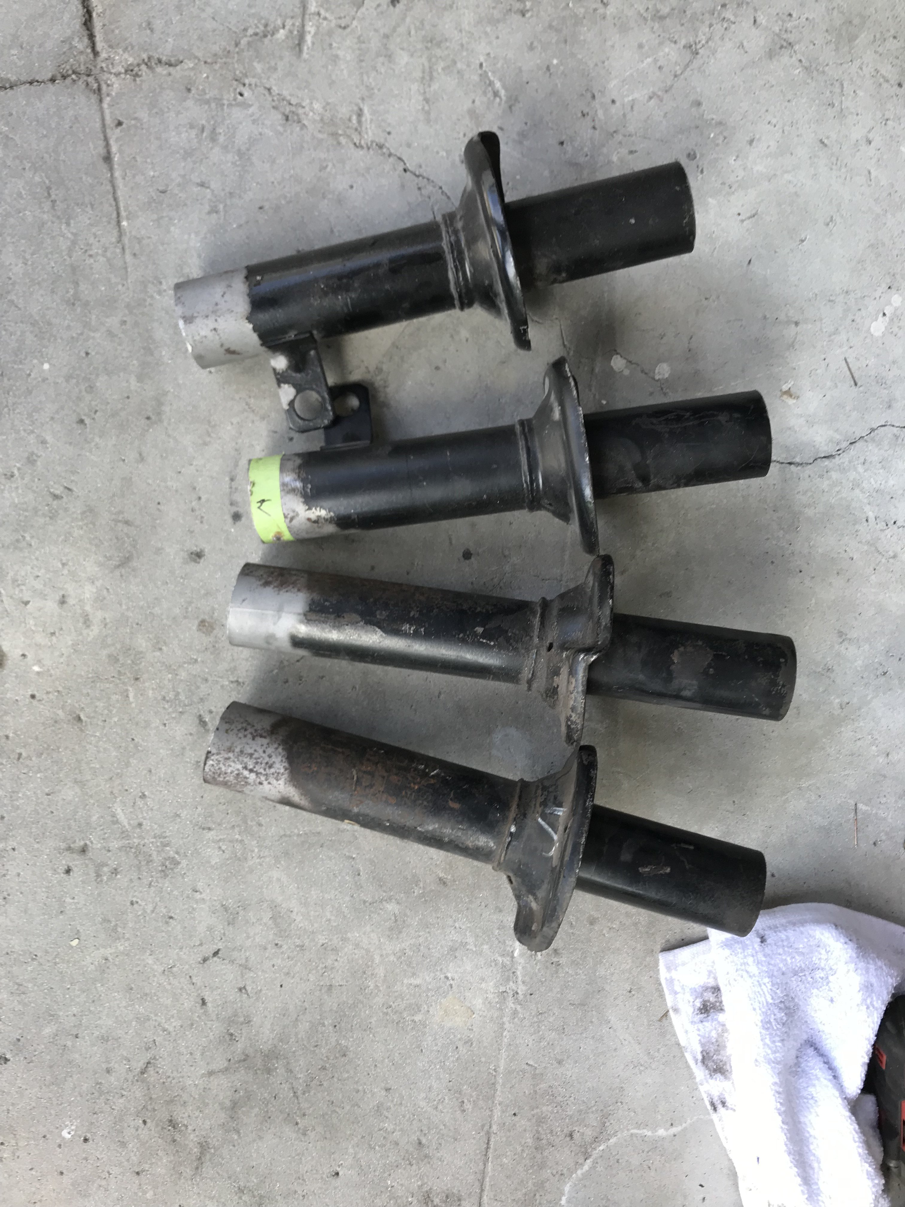
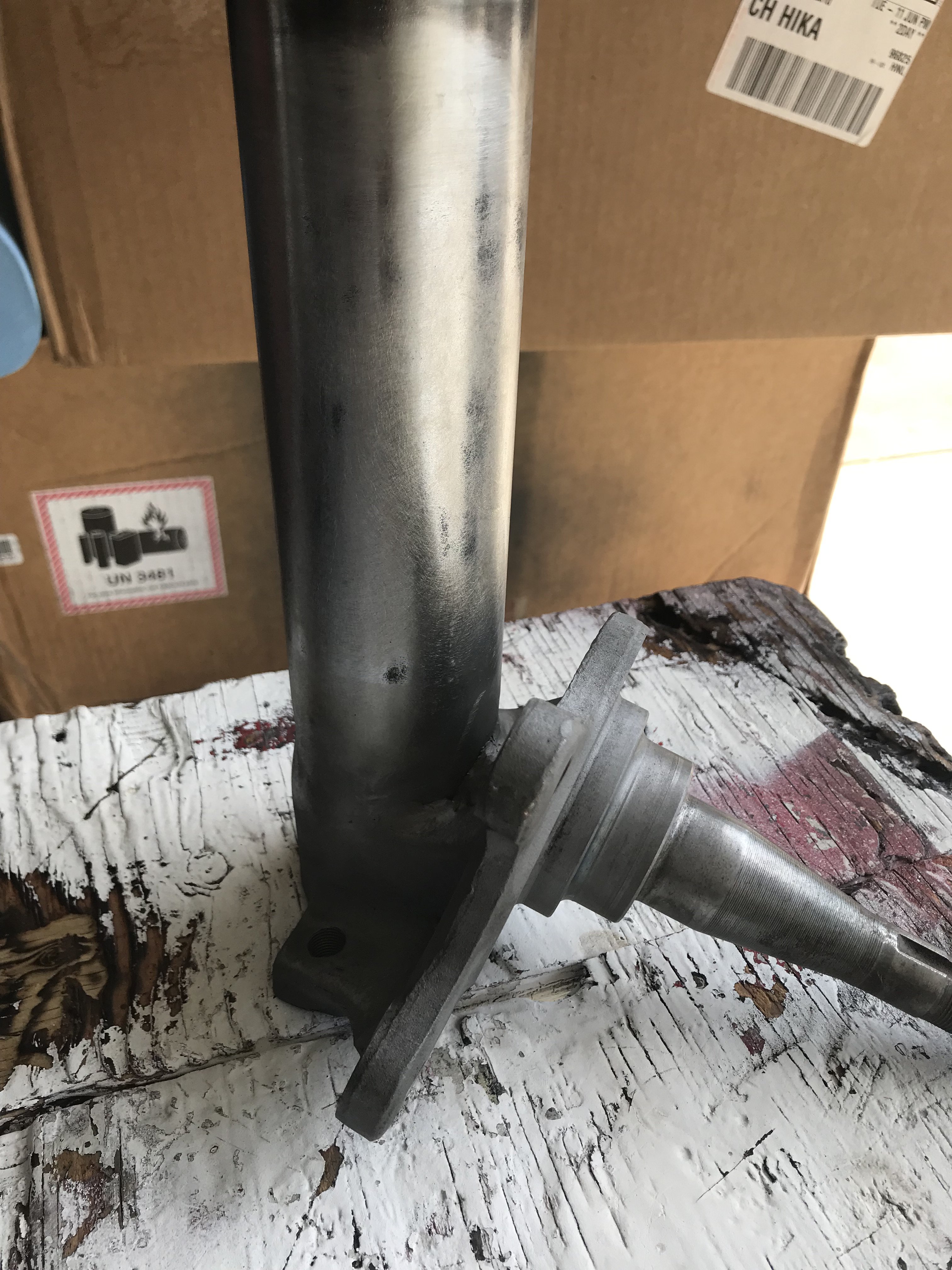
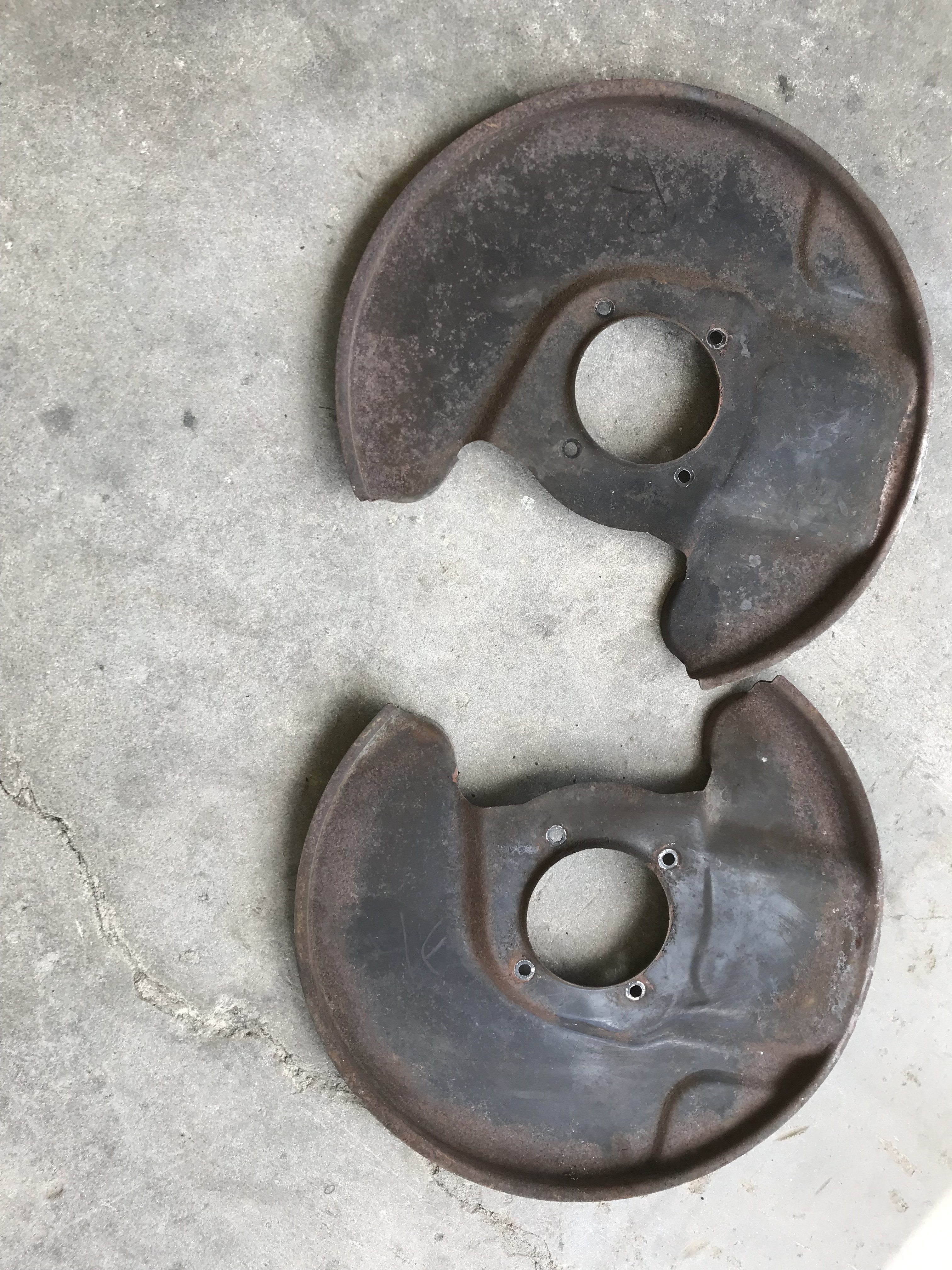
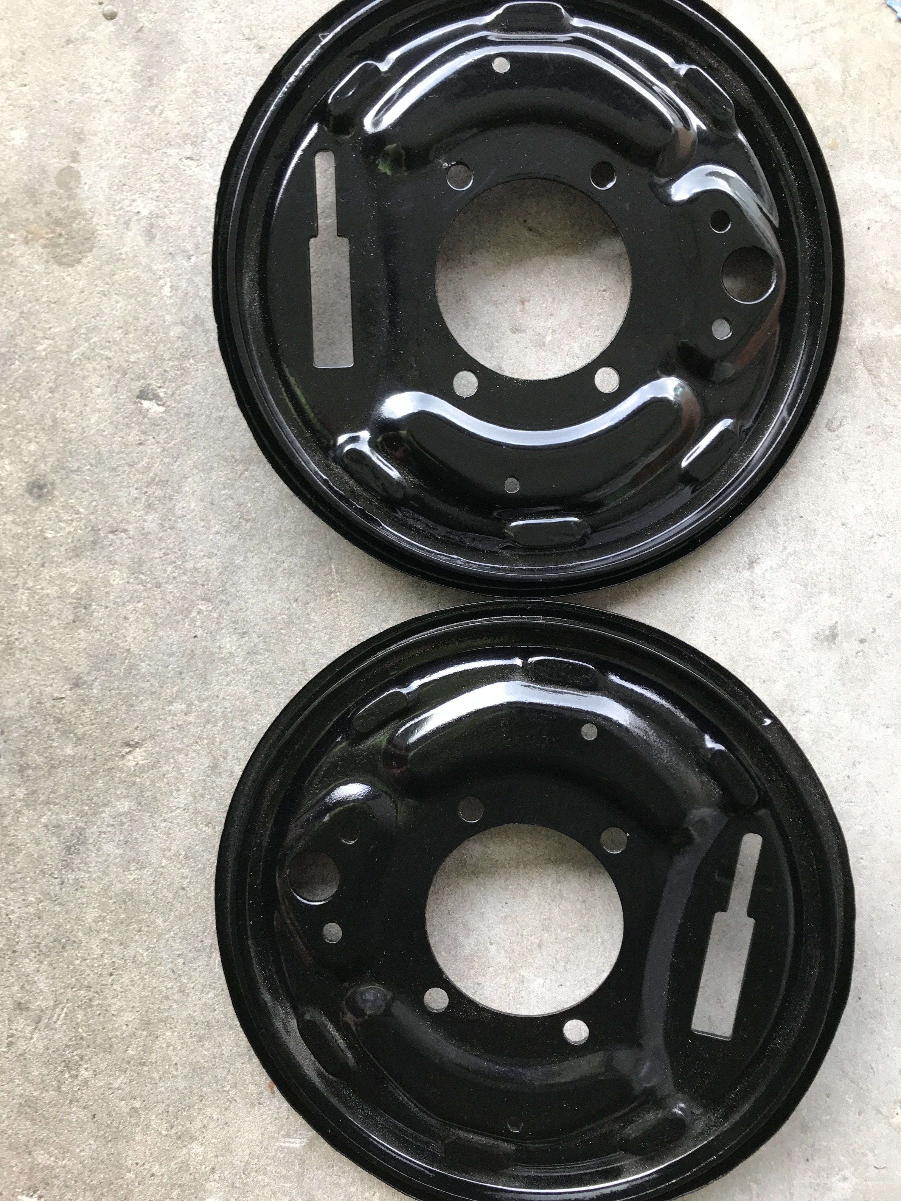
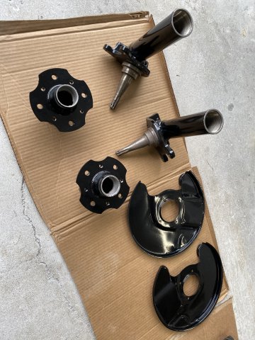
When the Postman brought a large box for me, I ripped it open immediately-it was my CRX Racing Coil Over Suspension kit. Shorter ones were for the Front and Longer ones for the Rear. The cost was $850 plus $150 for freight. CRX has installation instructions at their online site. Installation is simple. You cut about 2" to 2 1/4" from the bottom of the strut tube then weld the external sleeve to the strut base. Bottom sleeve and coil over strut section. I measured the length of the coil spring to record the spring preload. The lower threaded section allows you set the ride height that you want. Strut disassembly Struts were disassembled and sandblasted to prep for welding. After taping the cutting line, I started the cut by using a hack saw. Then a SAWALL was used to finish the strut sectioning. Sectioning completed The Front Spindles had a casting bump between the tube and spindle casting. I sawed a V cut in it to provide more welding space. The Rear Spindles don't have any casting lump. Welded up spindle All four struts were sent out for powder coating as it is too bulky for my small oven to heat up. All four Spindle Backing Plates needed cleanup to be powder coated. Front Backing Plates after Powder Coating Rear backing plates powder coated Hopefully, the Powder Coating guys won't take too long on the struts so I can put the suspension back together. Trying to decide whether to use Bedlinder(Raptor, etc). Anybody have any comments about Bedliners?
-
Heavy Duty frame rails and connectors
toolman replied to toolman's topic in Gen III & IV Chevy V8Z Tech Board
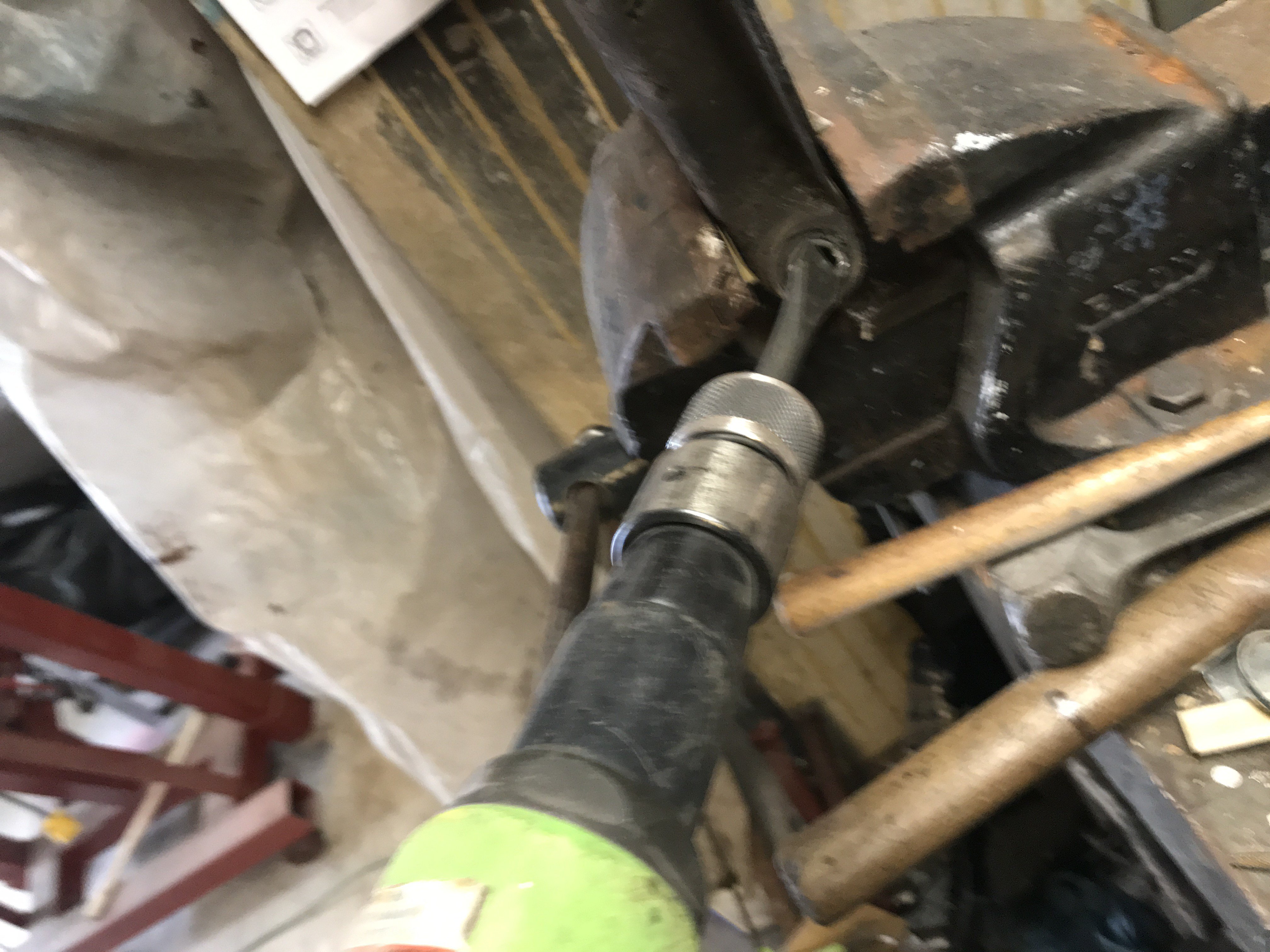
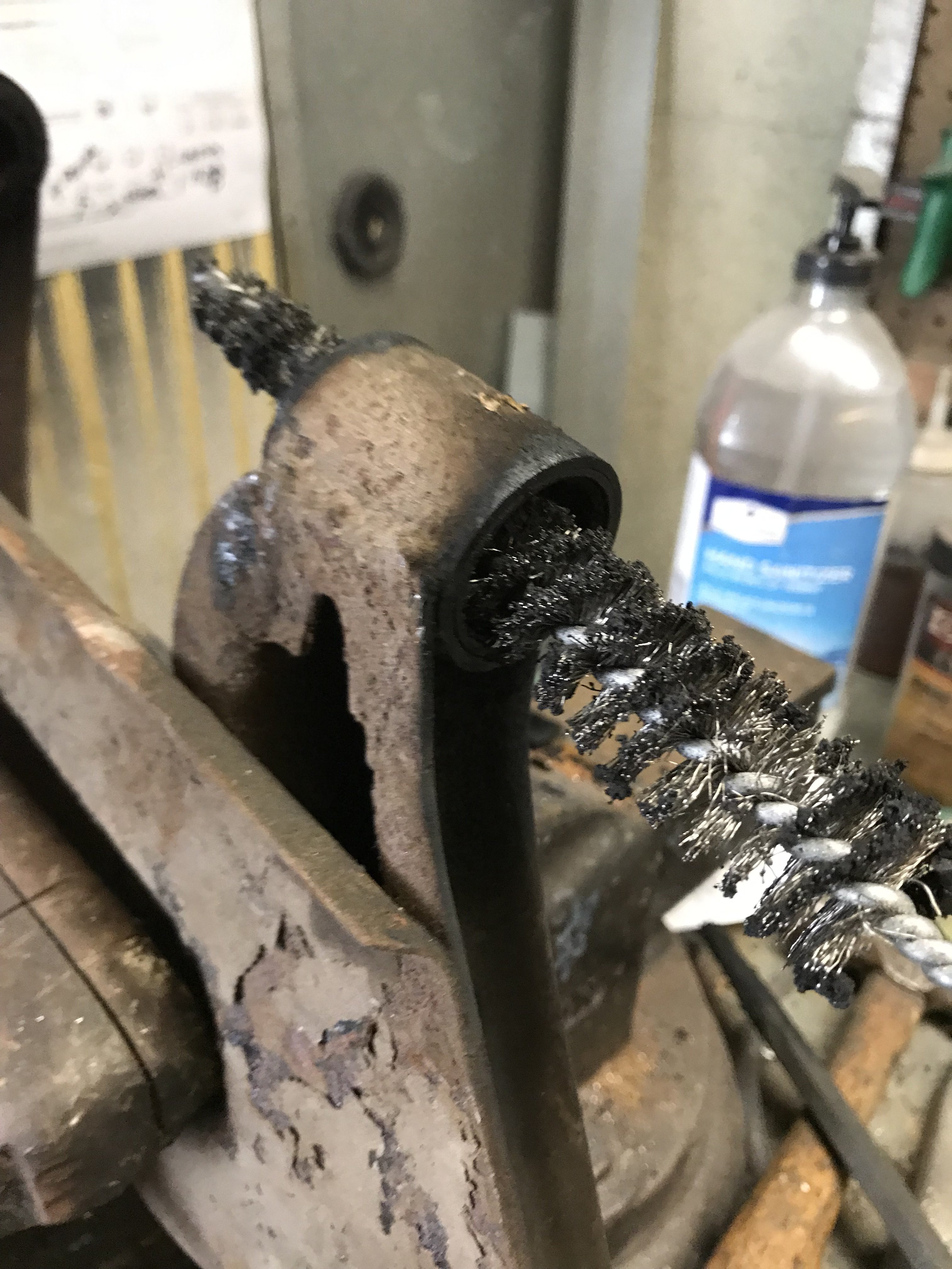
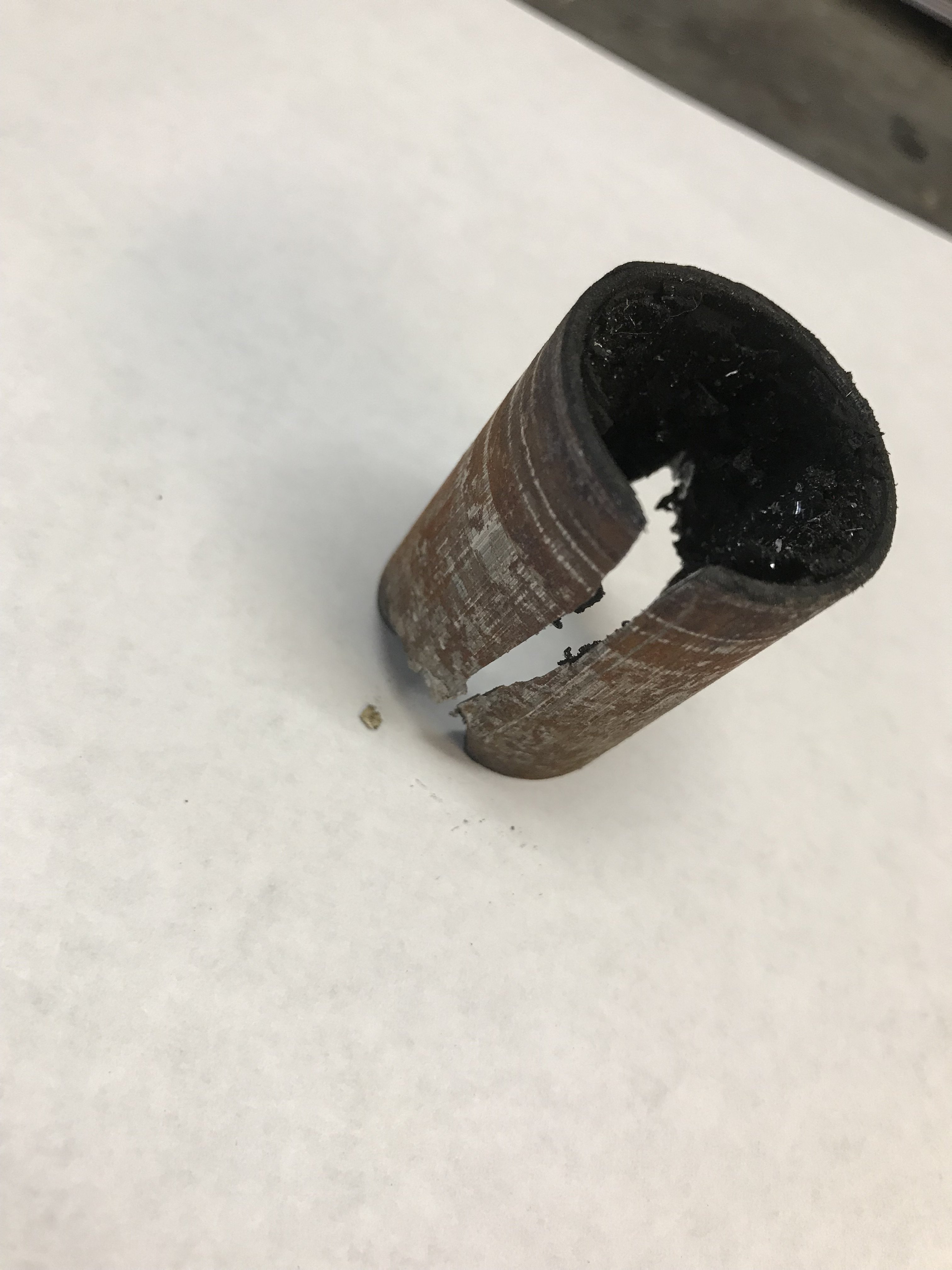
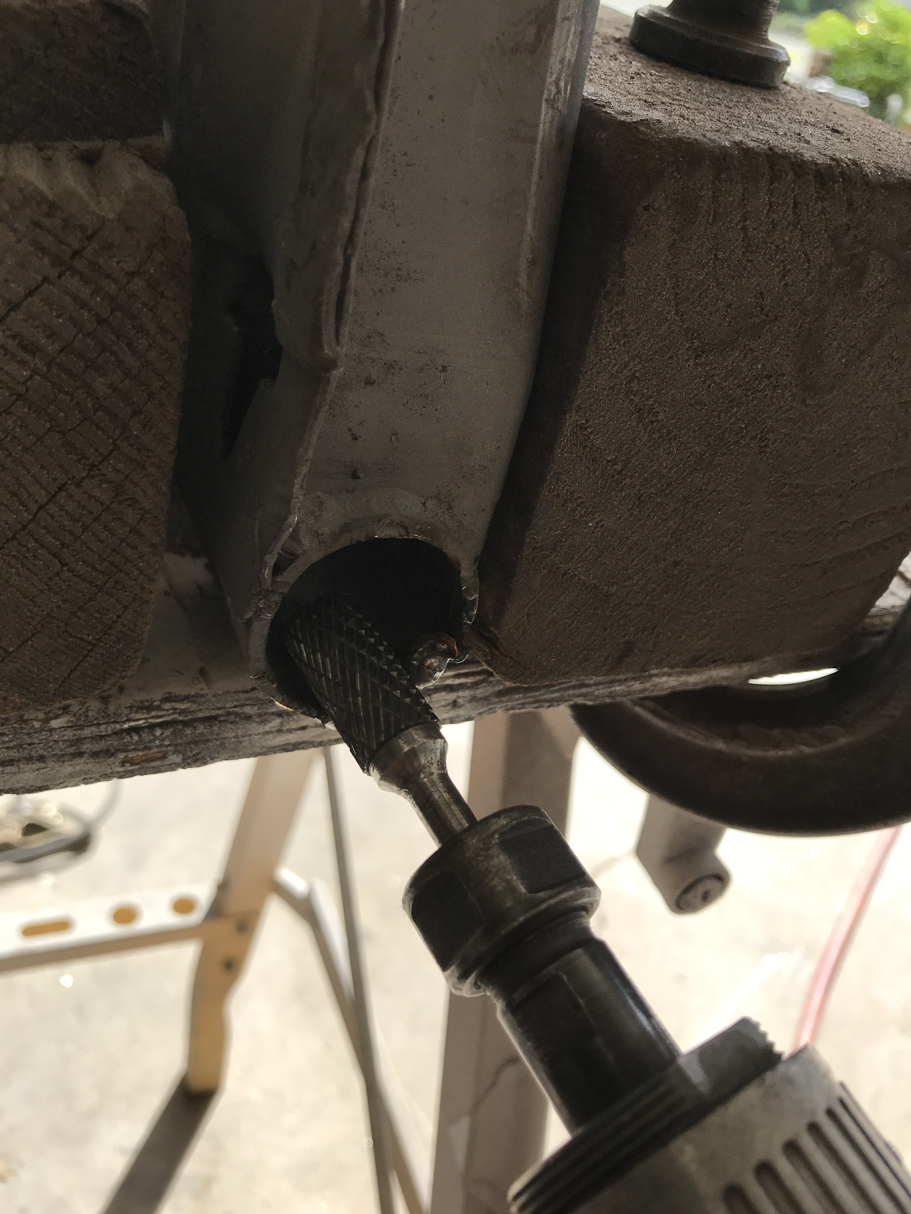
Next thing to work on was the rear control arms. First, I cleaned them up to remove any dirt and grease. Then, they could be sandblasted with #80 grit media. Next, removing their inner bushings was next. Using a air saw, I cut two parallel cuts in the inner metal bushing. If you don't have a air saw, you can use a hack saw. But you have to take the blade off the saw then stick in the bushing then reassemble the saw. Saw two parallel cuts through the inner metal bushing. Remove it and use a air chisel to push the inner bushing out. Try to get the bushing to collapse and fold over. If not, use a torch to burn away the rubber portion of the bushing. Besides the burning rubber, avoid being burned by hot rubber pieces. Remove all the rubber from the bushing with a wire brush. itself Now, use a Sawzall to cut two parallel cuts in the outer part of the bushing. Be careful not to damage the control arm while doing this task. Use a air chisel to collapse and push the bushing out of the arm. The removed outer bushing should resemble something like this. If the control arm was damaged while removing the bushings, you can repair it before installing the new bushings. The control arms ready for powder coating. . Control arm in my powder coating oven. Now, I have to wait till my control arm bushings to arrive so I can press them in.
-
Heavy Duty frame rails and connectors
toolman replied to toolman's topic in Gen III & IV Chevy V8Z Tech Board
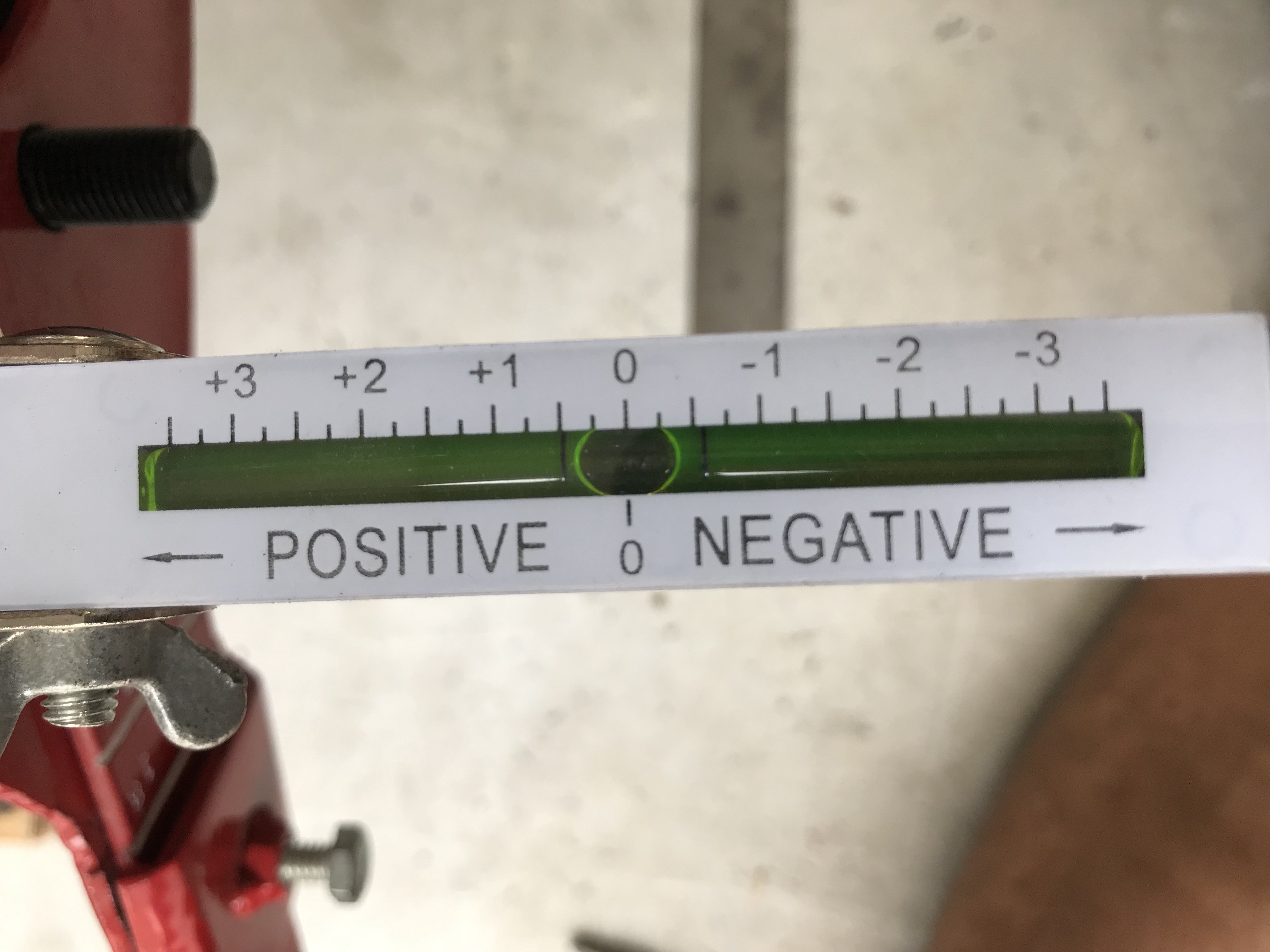
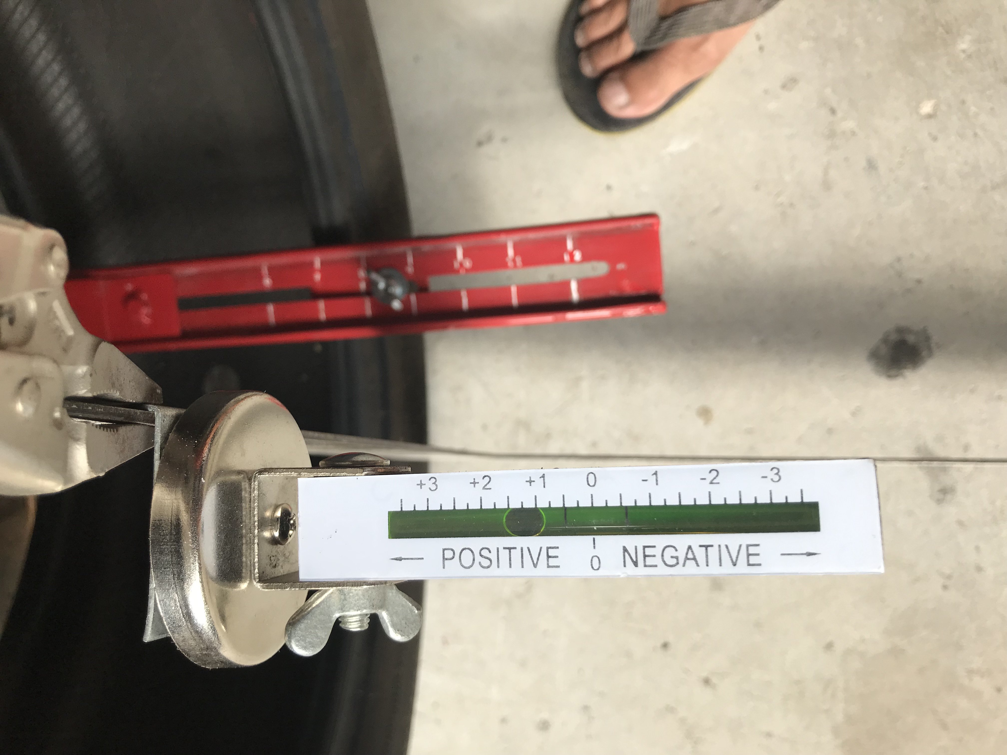
The wheel fitment tool was designed to go to even a 12" wide tire. As I only had a 8" wide tire, one has to imagine the other 4" extending inside the fender. First, Zeroing the Camber gauge Camber gauge zeroed in. Then, holding the straight edge with camber gauge against the outside of the tire. The Camber reading is 1 1/4 degrees Pos This wheel/tire combination would require a 3" fender flare. In this case, the wheel had a 2" Negative offset-the wheel center was 2" inward of center of the wheel. The 245 X 18 X 8 offset wheel/tire combination looks like this from the front view. A mild street look. . Do not forget that the ride height is still not correct. The present ride height is about 3" to 4" higher than what it will be with the new coil over suspension. Lowering the vehicle will create negative camber and bring the camber to closer to a zero reading. Also, keep in mind, these are only simulations and I am going to larger tires and wheels.
-
Heavy Duty frame rails and connectors
toolman replied to toolman's topic in Gen III & IV Chevy V8Z Tech Board
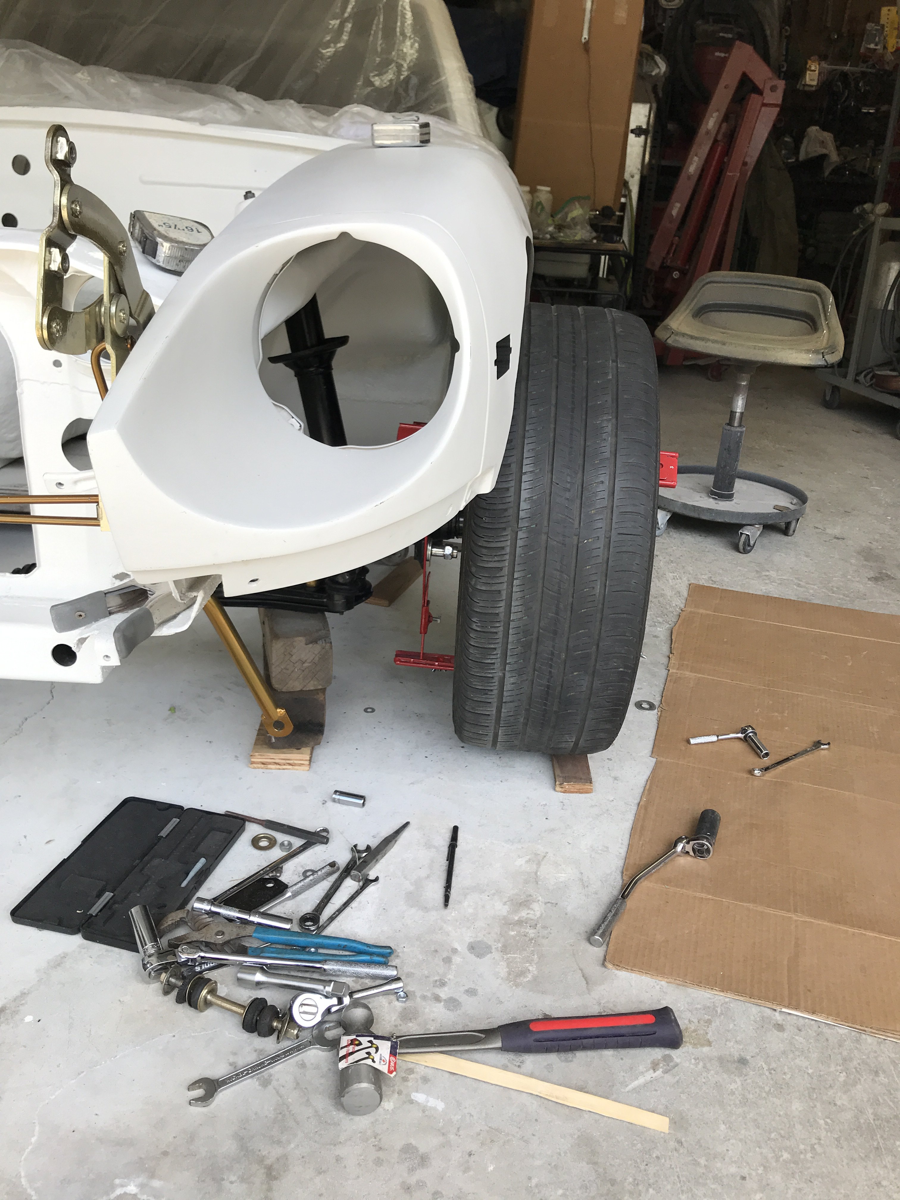
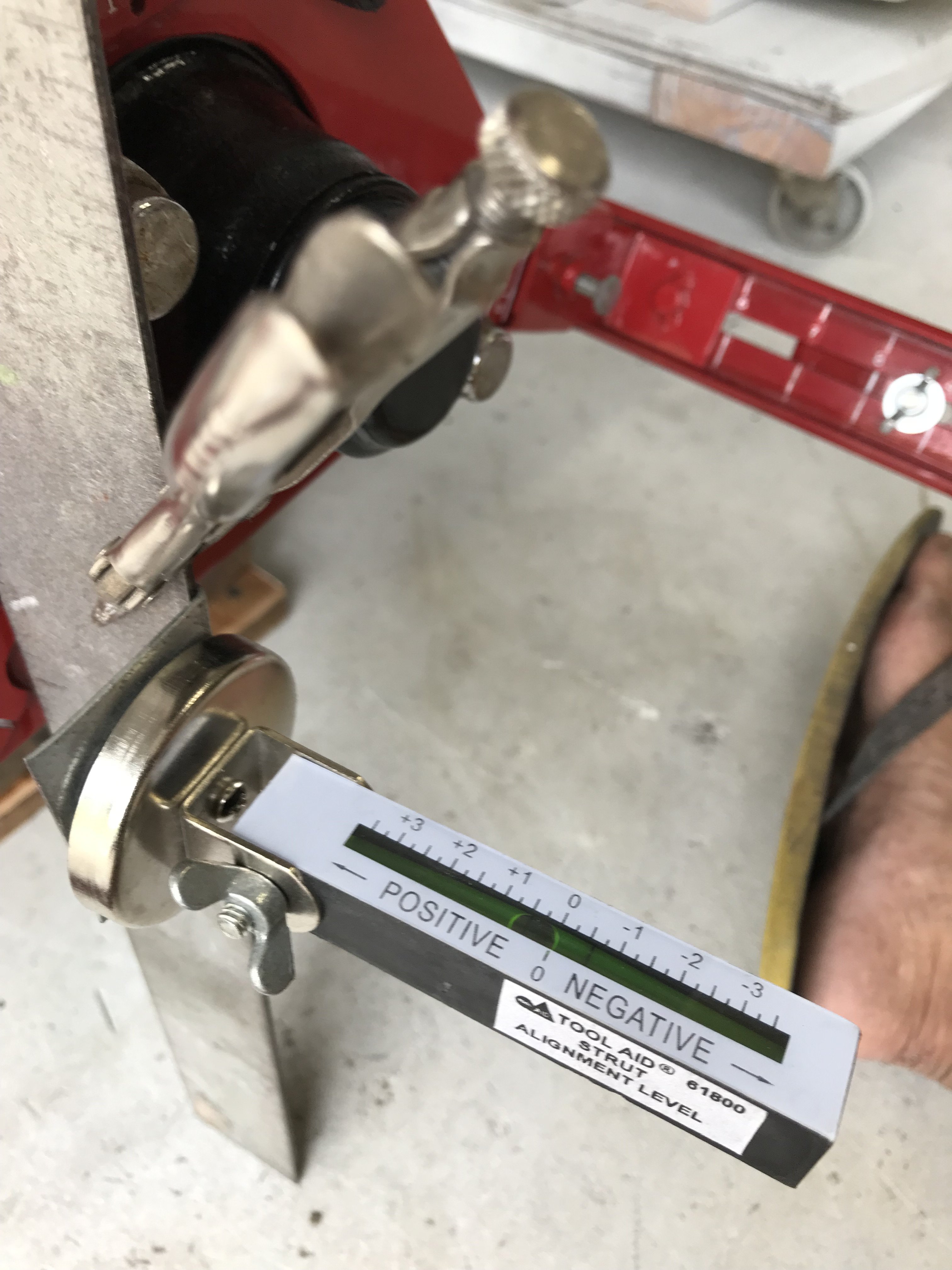
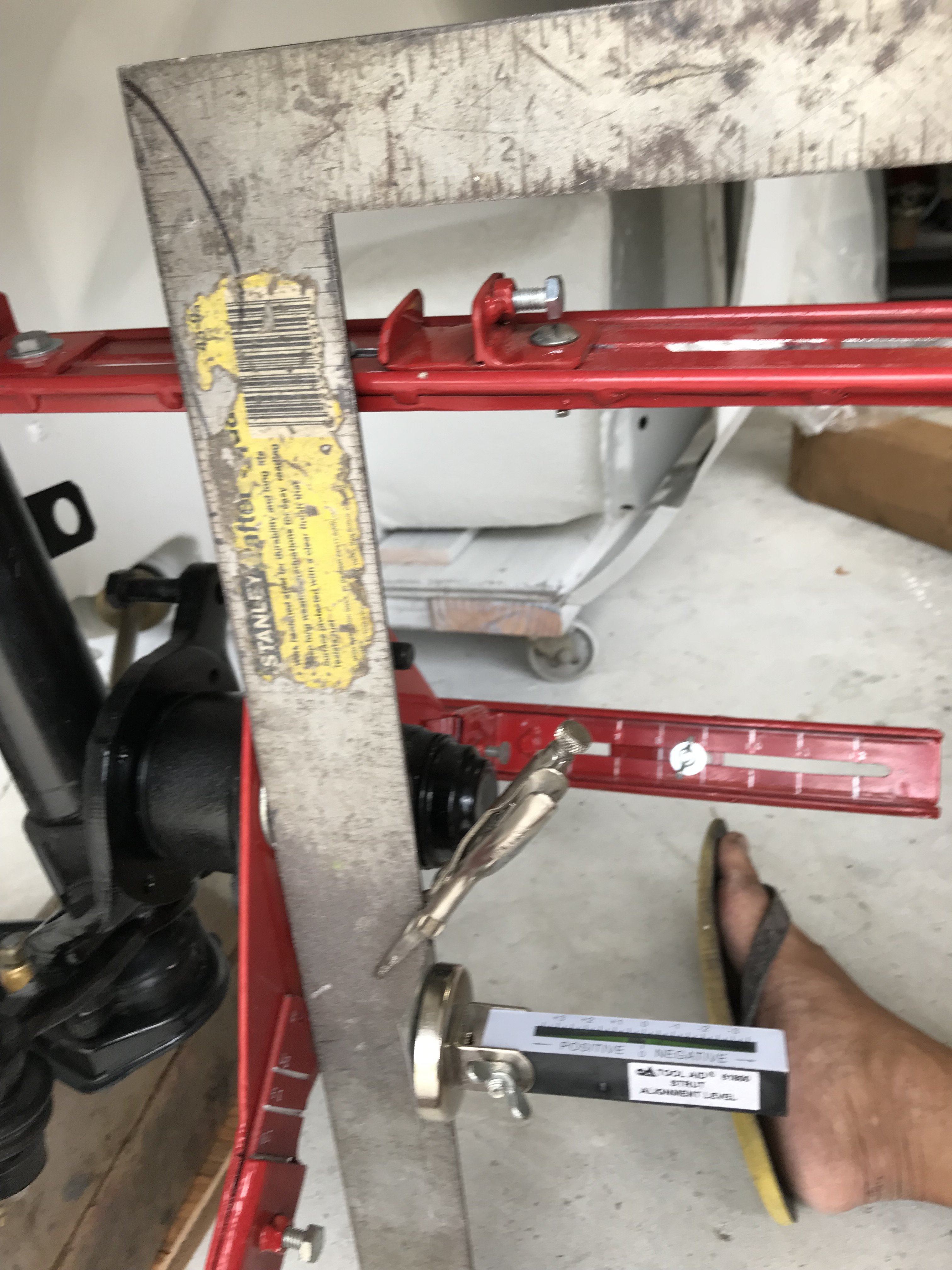
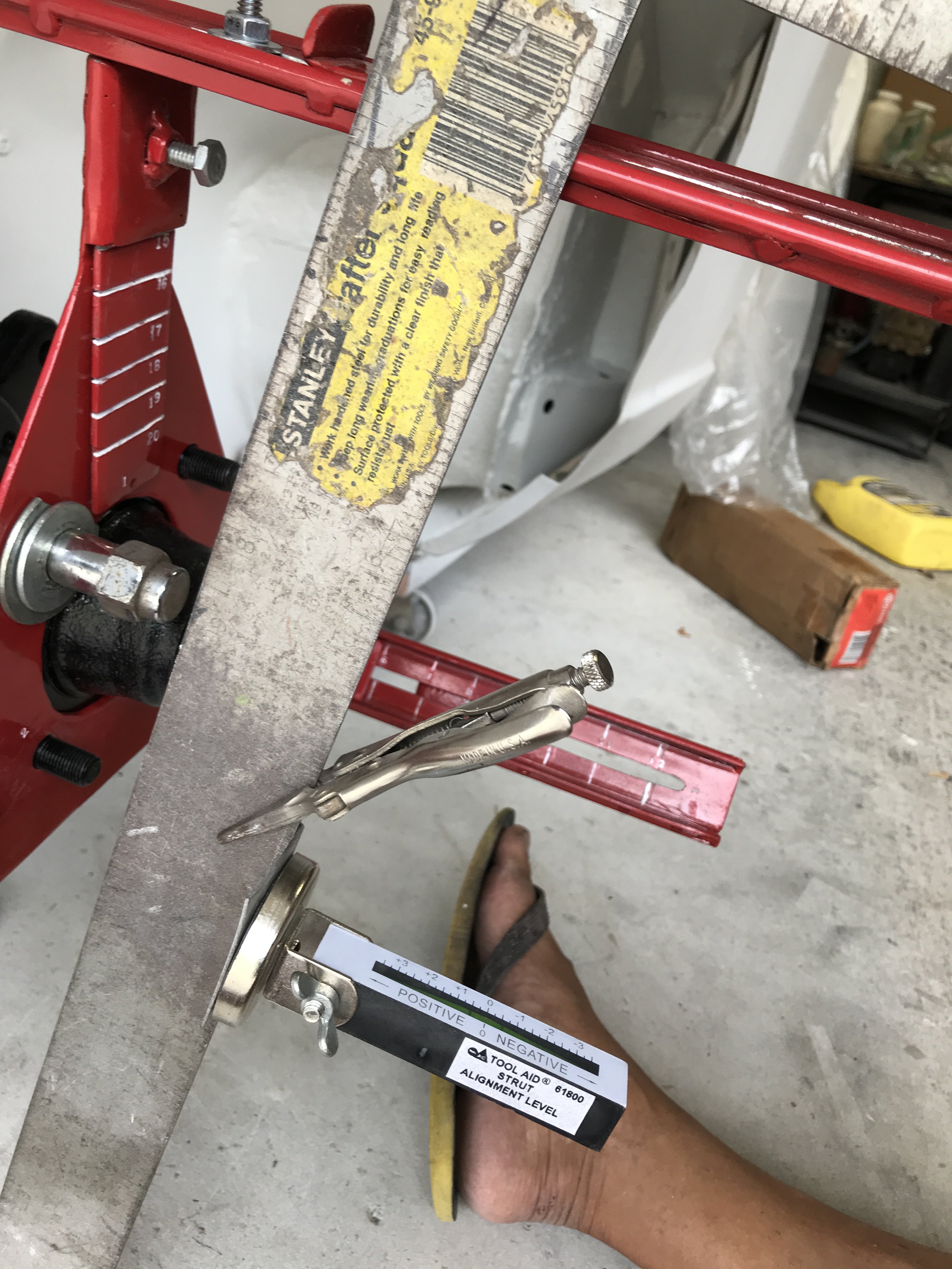
Back in 1971, this 71 240Z was my First and Only Car. It was a Total Wreck- the owner ran it into a large Bulldozer parked on the side of the road. My father owned a automotive body shop which had 5 frame machines. We fixed often repaired totaled cars. So we put it on the frame machine and pulled it straight with multiple 10 ton hydraulic rams. Then the damaged pieces were replaced with OEM parts. I drove the car "stock" for about a year but decided it needed more power. I first checked into modifying the Nissan 6 cylinder motor by Weber carbs, turbocharging and 5 speed racing transmission). But those options were way too expensive. Being a Chevy drag racer, putting a Chevy 327 motor with Turbo 400 transmission seemed like a easy answer. So after gathering all of the needed parts, I pulled the old six engine out and put the 327 in. I had the car running in a week time because I had to use vacation time to do the conversion. At a later date, I put a more powerful 350 and T-5 five speed trans and put metal flares on. In 1988, I bought my second car 88 Chevrolet Astro Van for business. My 240z was basically sitting in the garage since that time. So I owe it to spent some time restoring it as the best that I can do. I hope this story explains my restoration. Back to the restoration: I put the Wheel Fitment Tool on the car to check the wheel alignment out. But first, had to remove the strut coil spring as it won't allow the body to drop as there was no engine weight and accessories. Took out spring Put the Wheel Fitment Tool to test it out. Wooden blocks were placed under the lower control arm to adjust ride height. The car is still on a dolly which lifts the vehicle about 1" higher than a stock Z. Using a Tool Aid Wheel Alignment gauge to check Camber readings. A carpenters square shoed the hub to be close to zero so I set the gauge to zero degrees, After checking the Square with the ground, I reversed it to better demonstrate camber. By tilting the straight edge top outward(away from the car) to stimulate Positive Camber. Positive Camber To stimulate Negative Camber, I titled the top of the straight edge inward( toward the engine compartment). Negative Camber I think there was a misunderstanding about what I trying to accomplish. In my particular case, I am trying to eliminate as much Negative Camber that I can. Lowering the car with shorter springs, lower ride height, extra wide wheels,etc will create a lot of Negative Camber. Shortening the lower control arms, upper camber plates, modified spindles,etc maybe utilized to provide Positive Camber to achieve alignment. My car will be basically a Street Car and not a Race Car requiring 3 degrees Negative Camber. Now, you can even change front and rear crossmembers to get the alignment that you want.
-
To me, Apex Engineering did an excellent job on both front and rear suspension upgrades. Considering the upgrades are basically a bolt on kits, a lot of thought went in its design. The only problem that I can see is having the rear coil overs operating in the hatch area. In a race car, the noise and danger from moving parts in the passenger compartment would not be a problem. In a street car, those problems would arise. However, maybe they thought of it and have conventional struts that would work instead. Awesome design. I would consider using the rear upgrade as I will have a Rocket Bunny Body Kit.
-
Heavy Duty frame rails and connectors
toolman replied to toolman's topic in Gen III & IV Chevy V8Z Tech Board
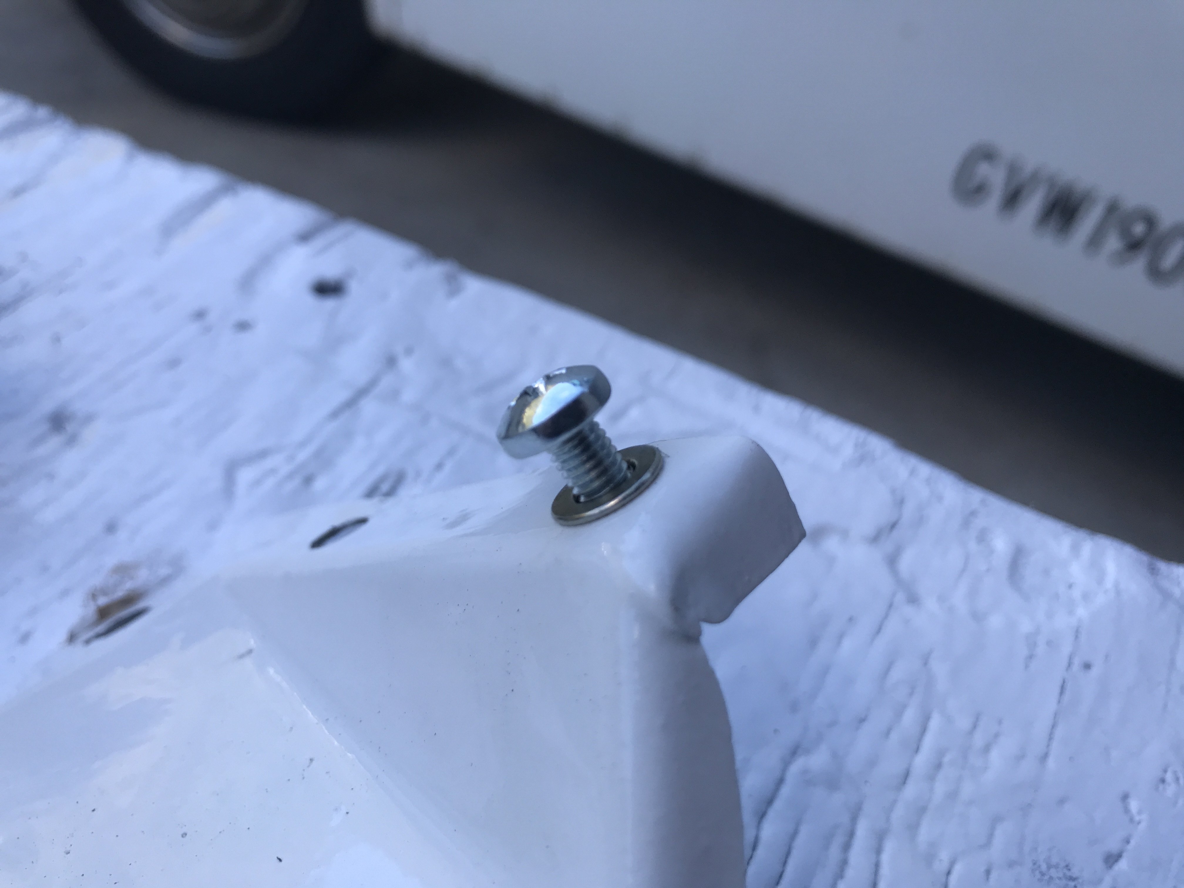
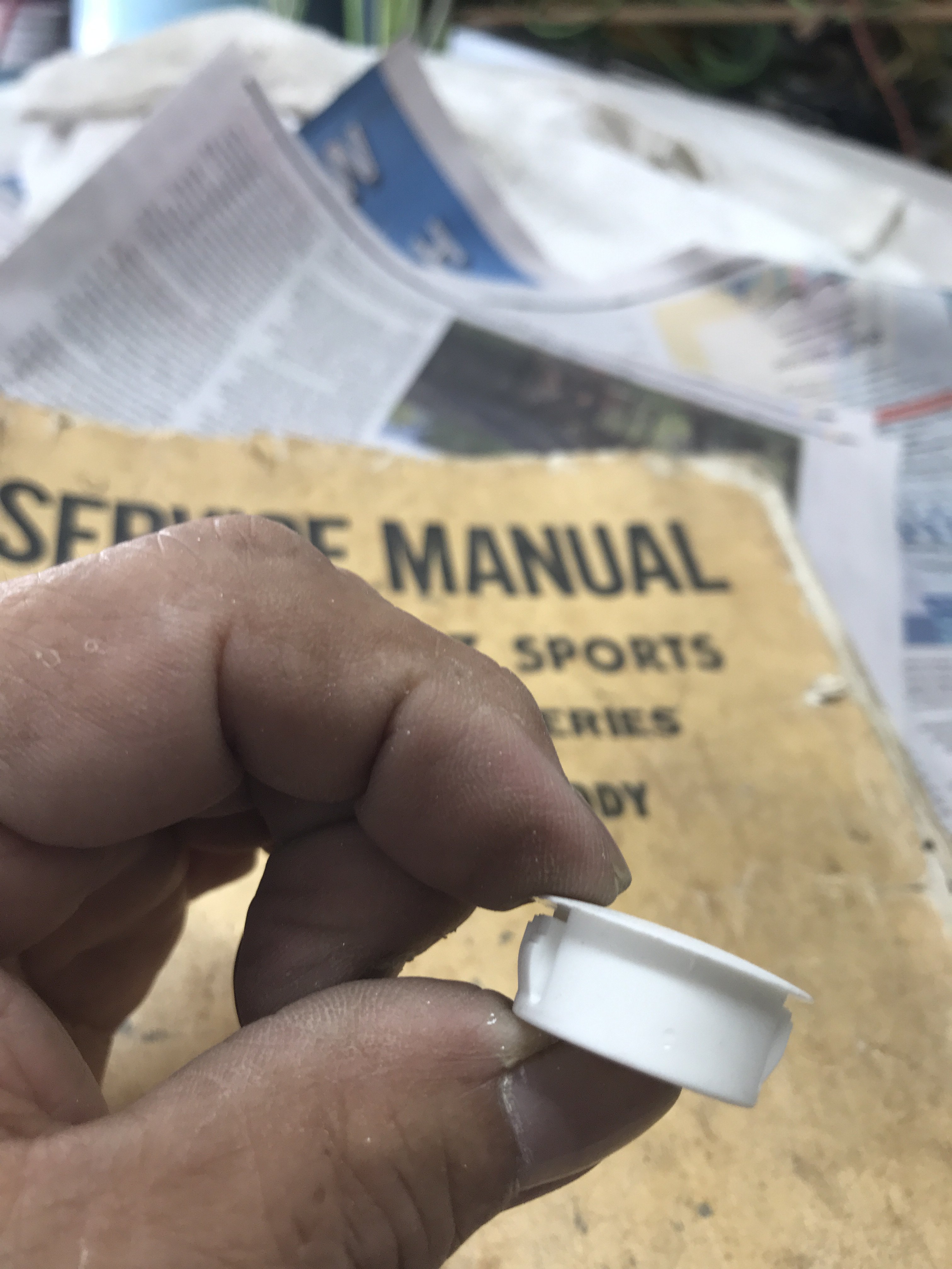
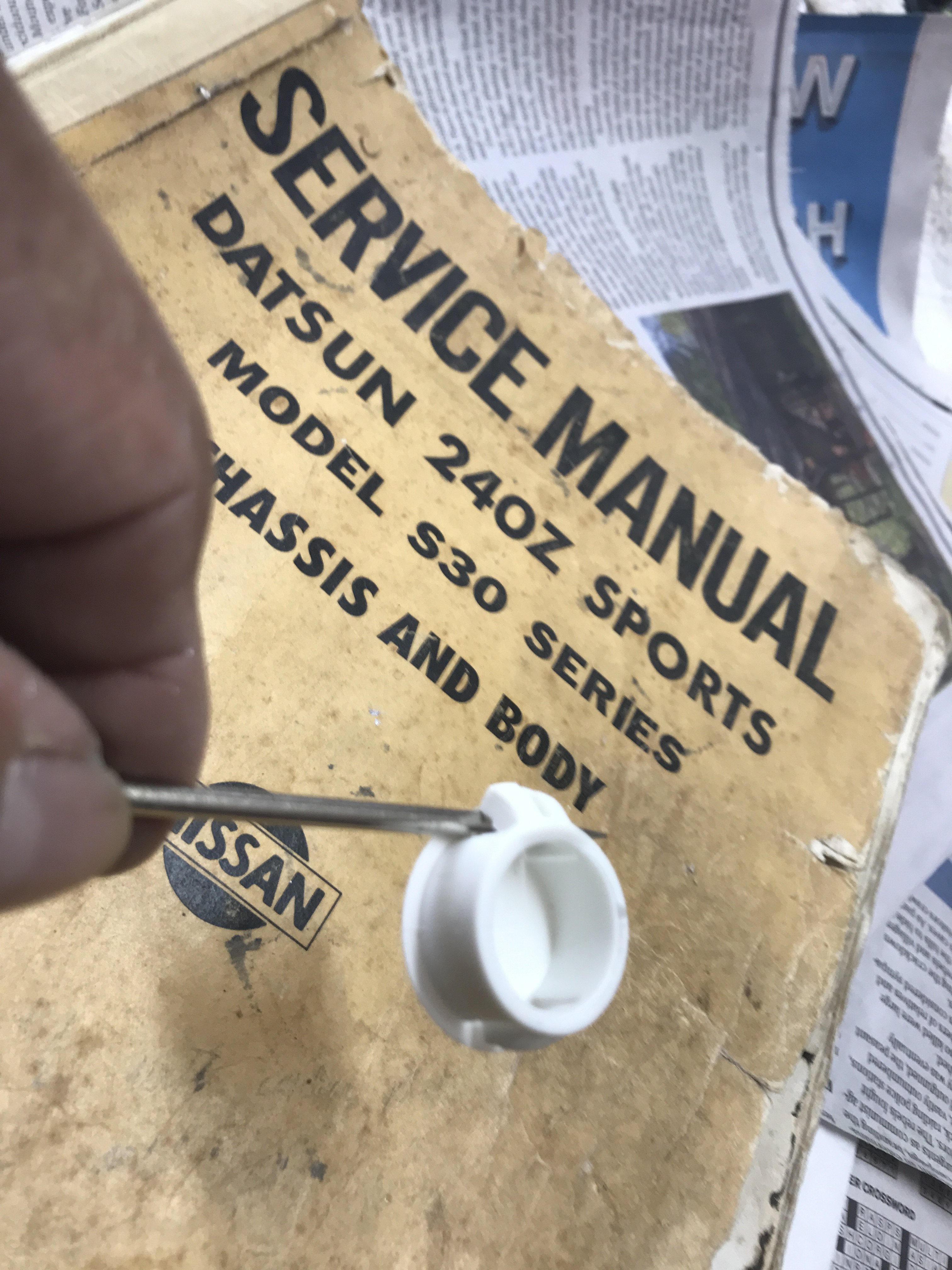
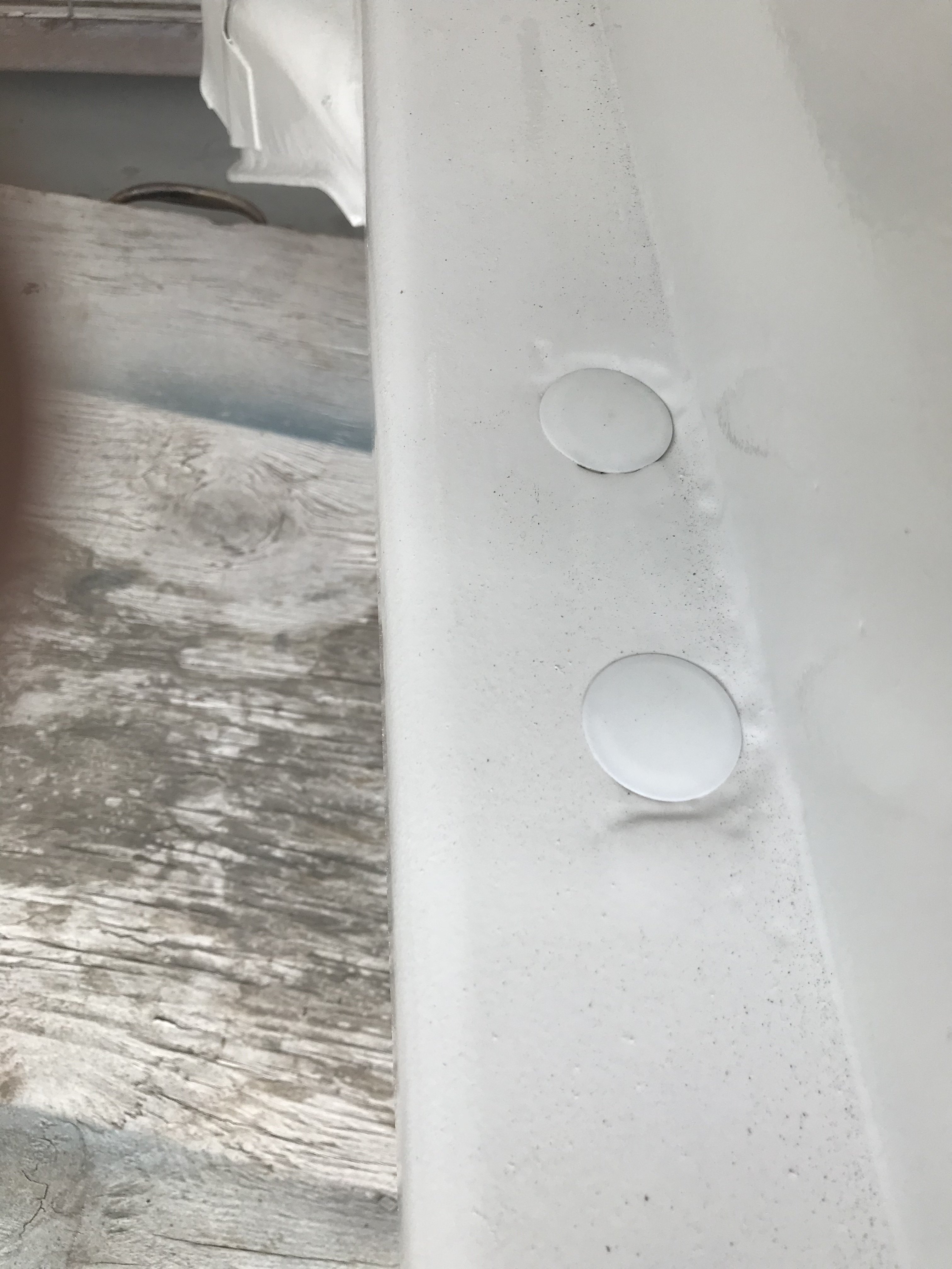
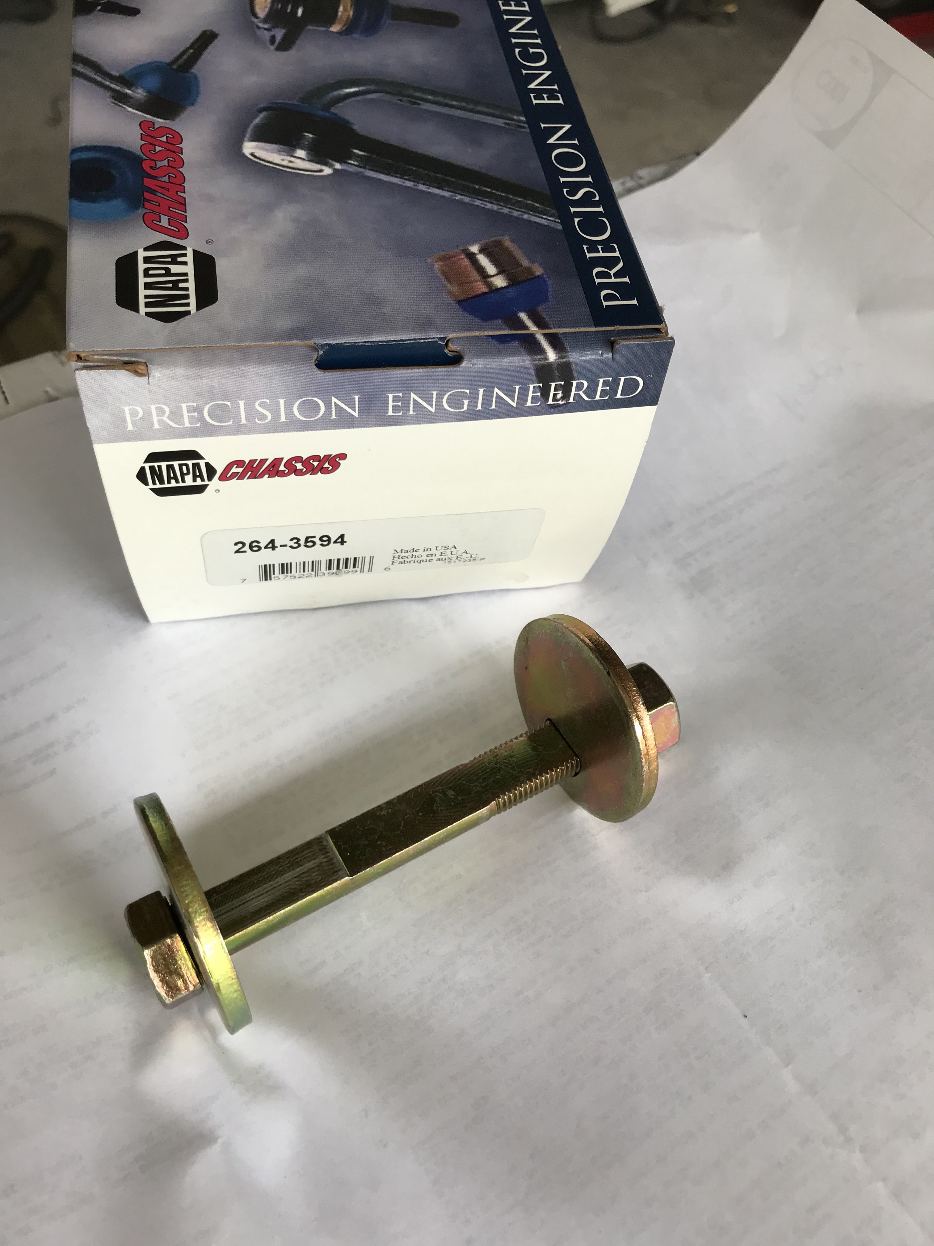
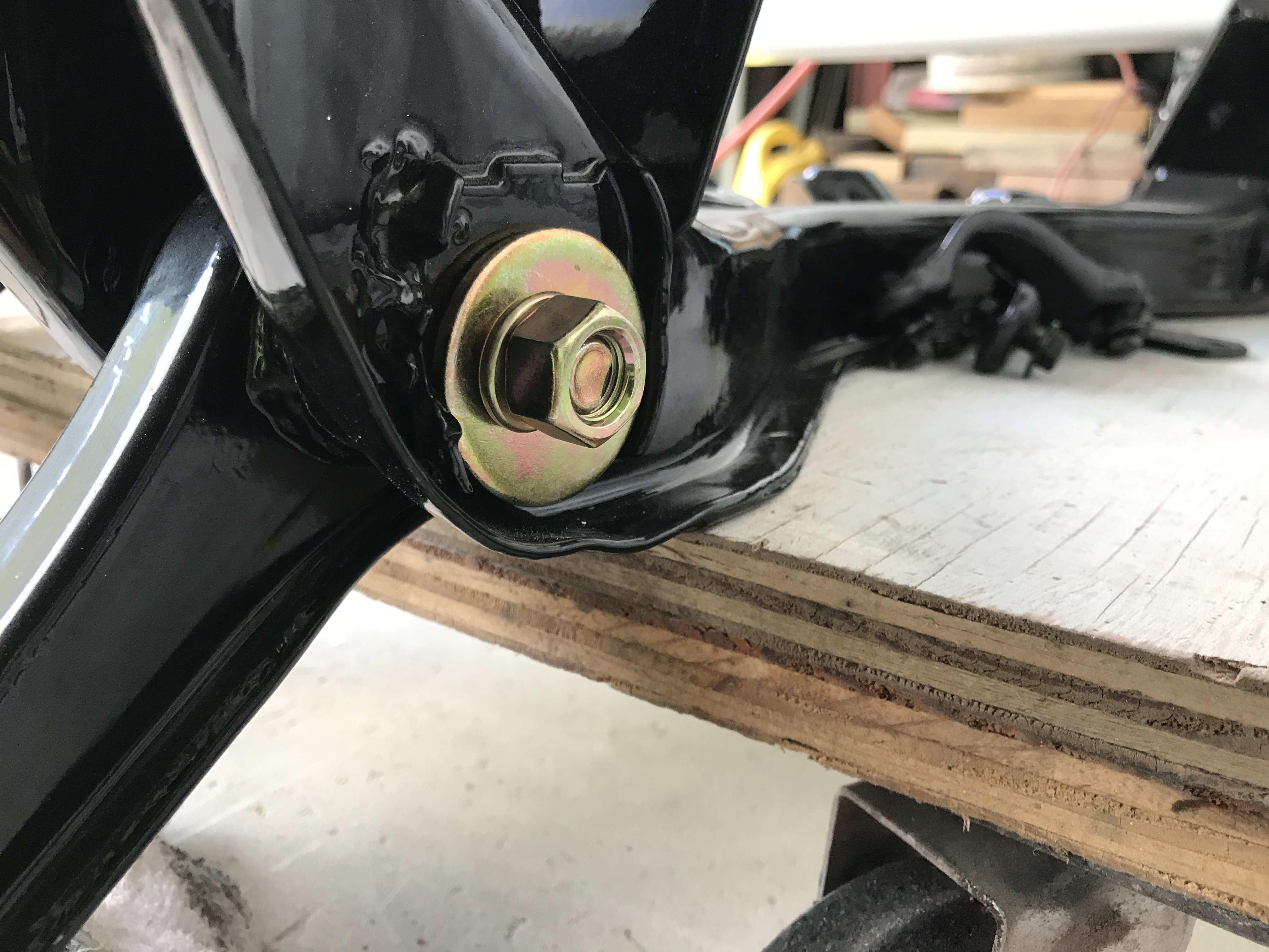
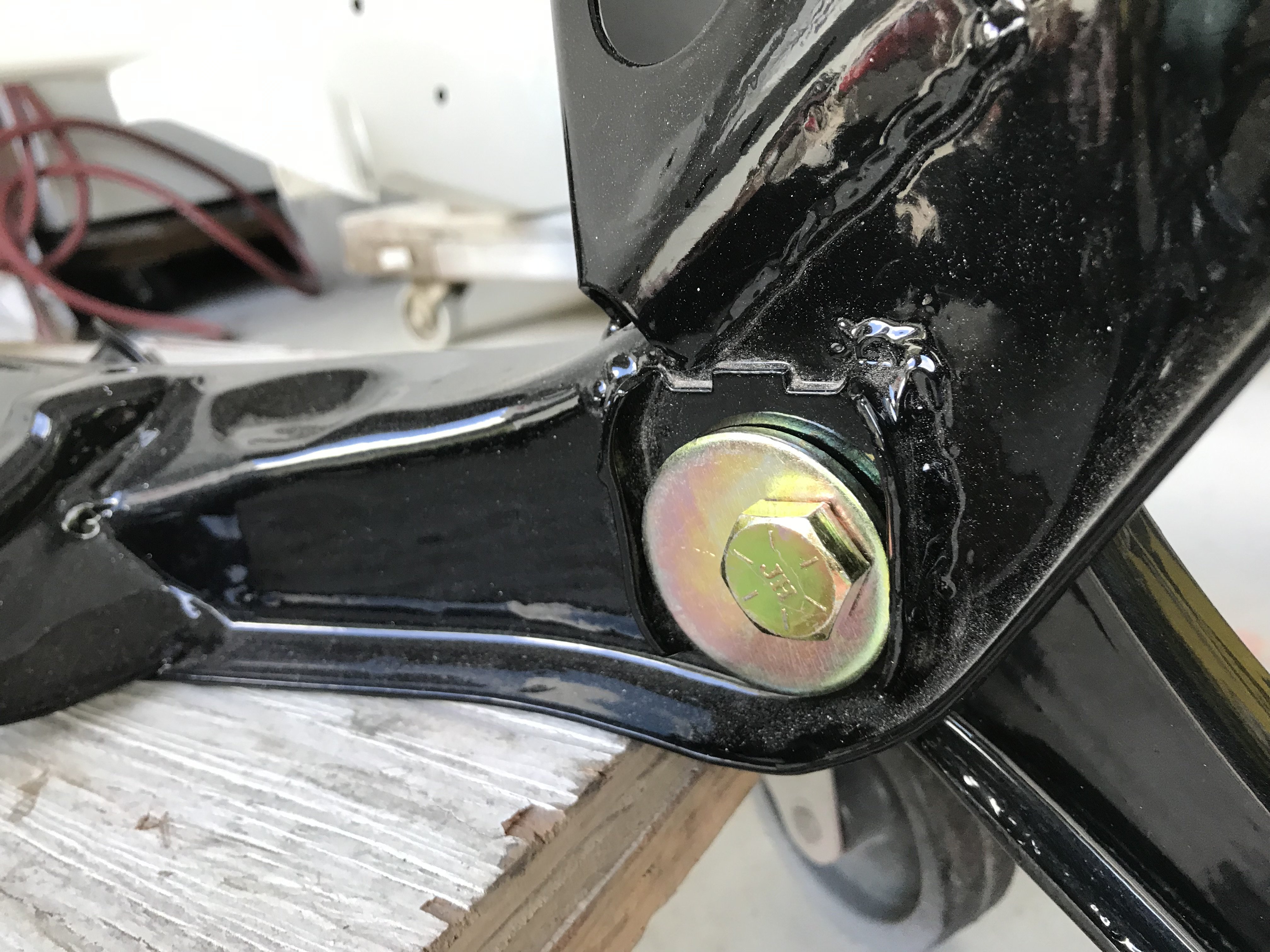
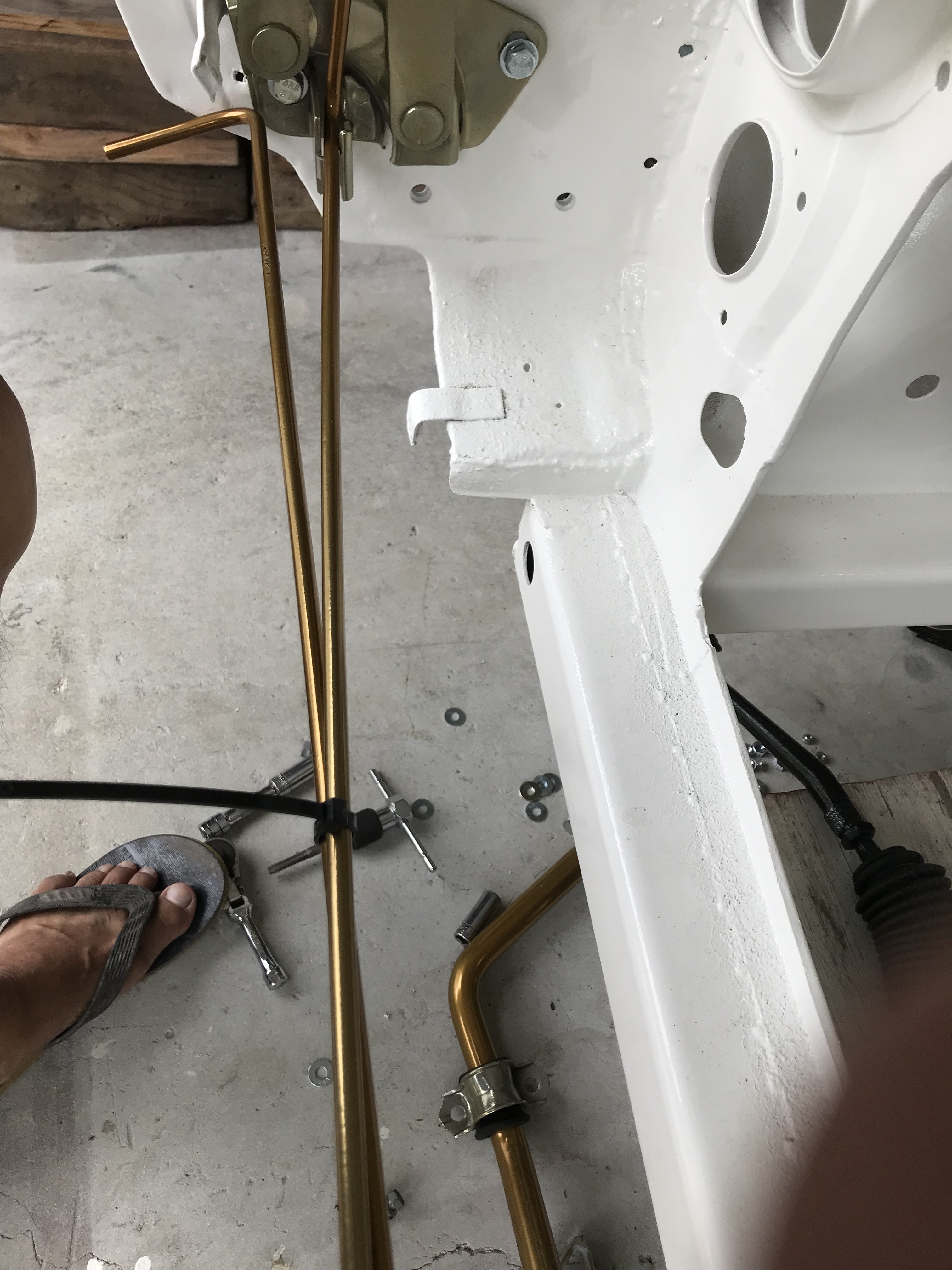
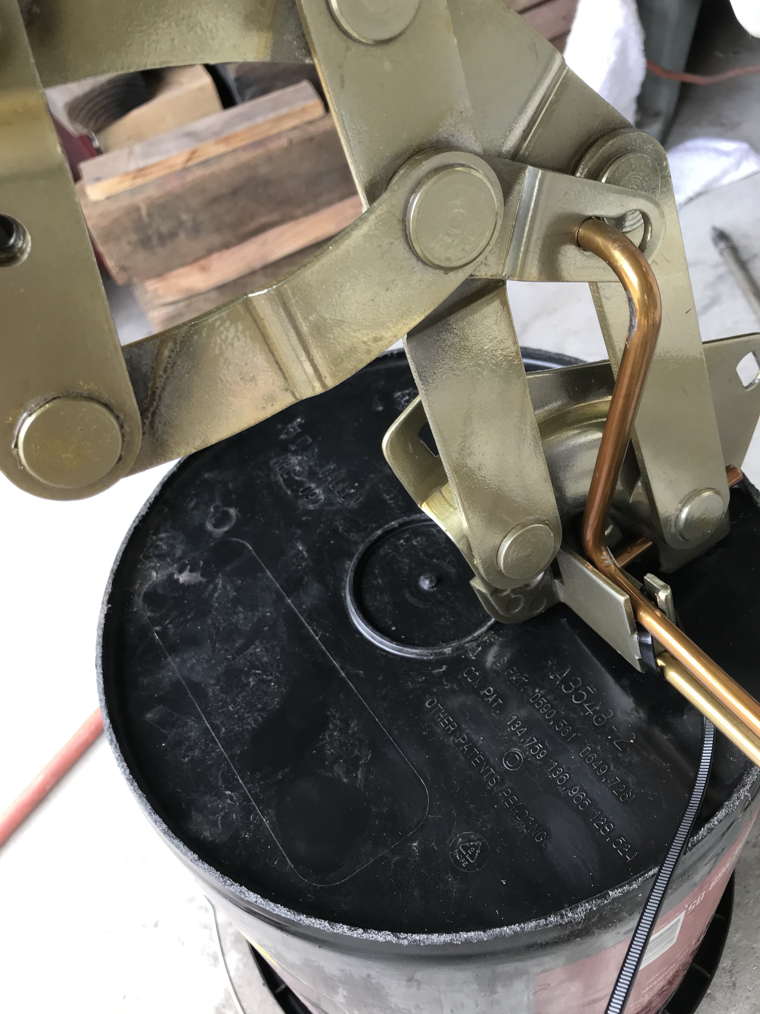
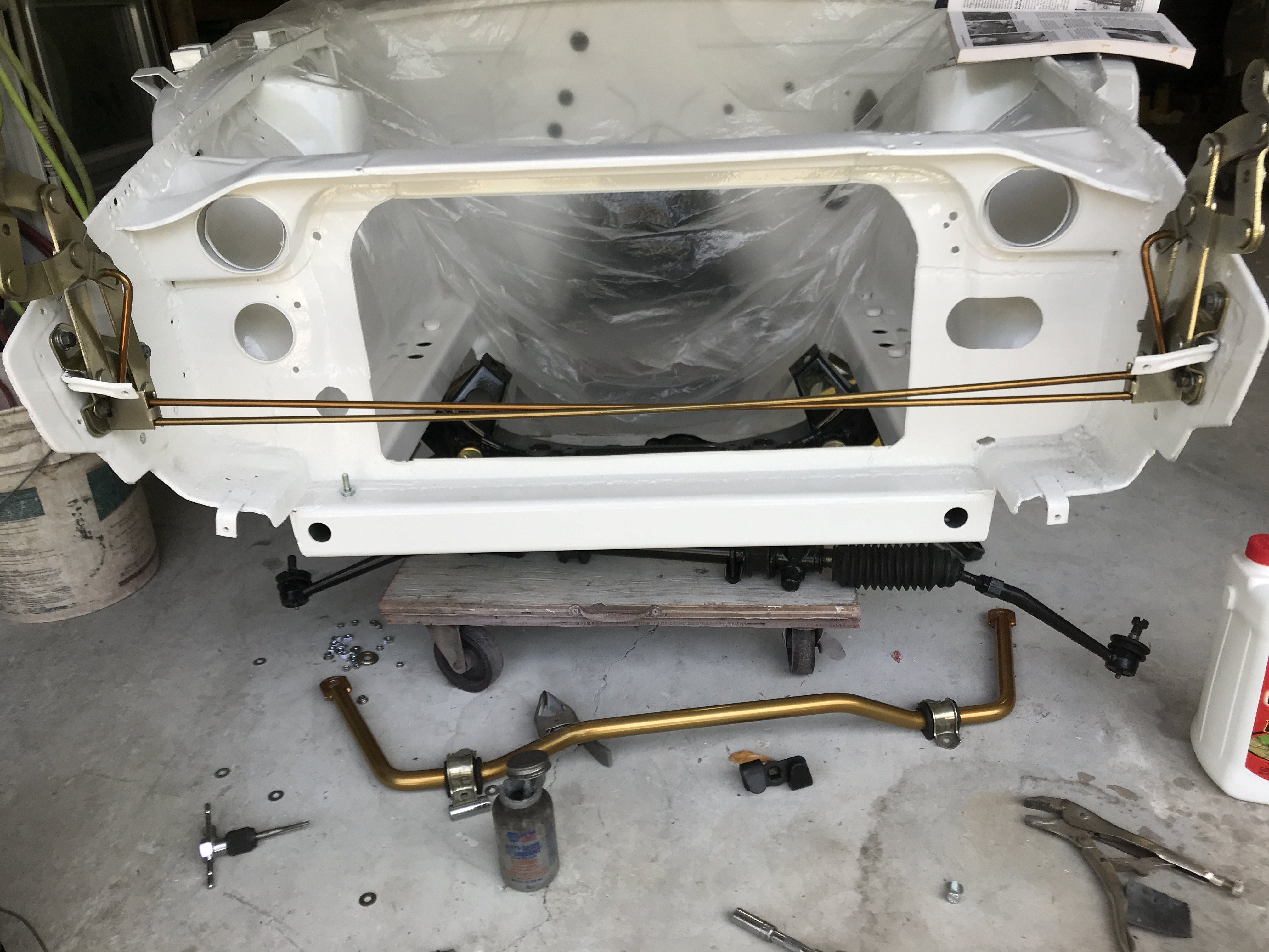
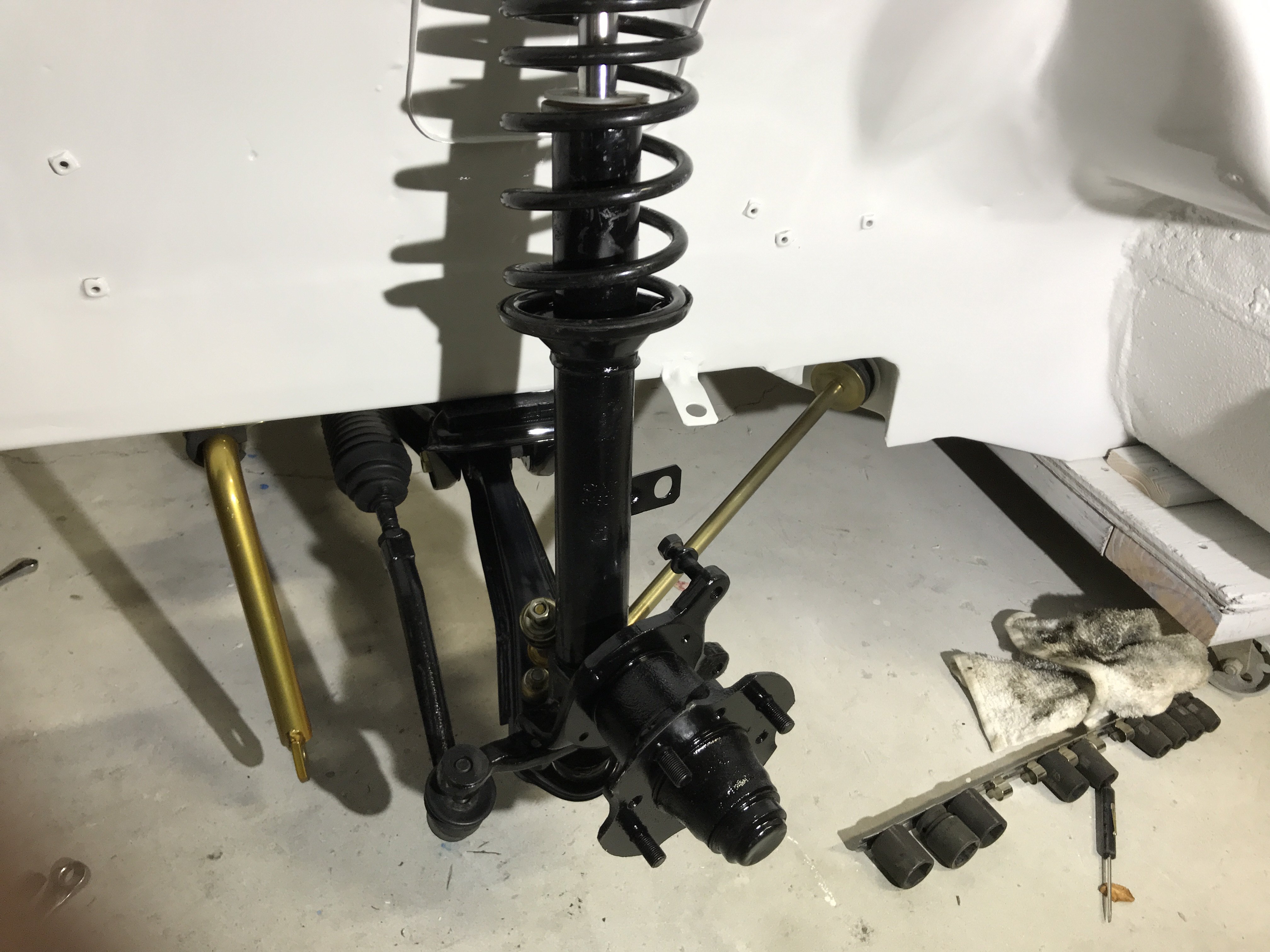
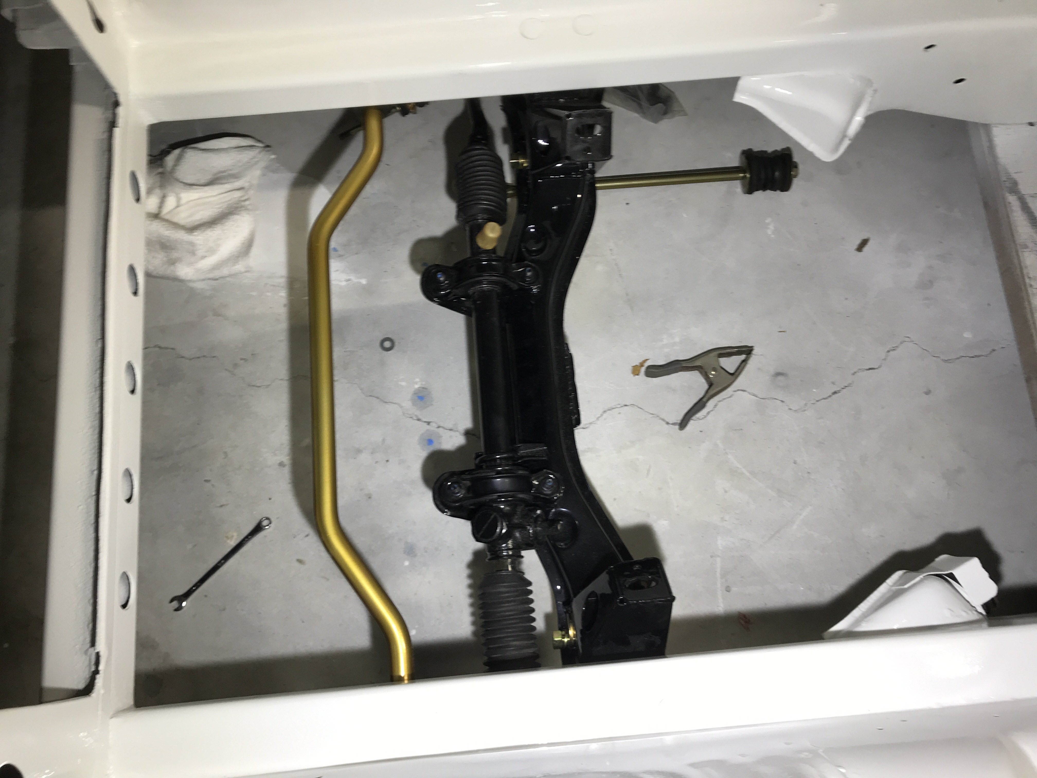
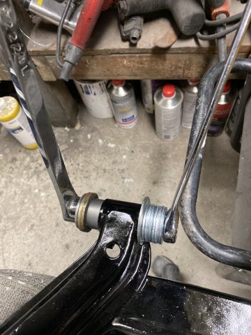
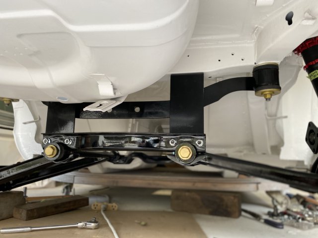
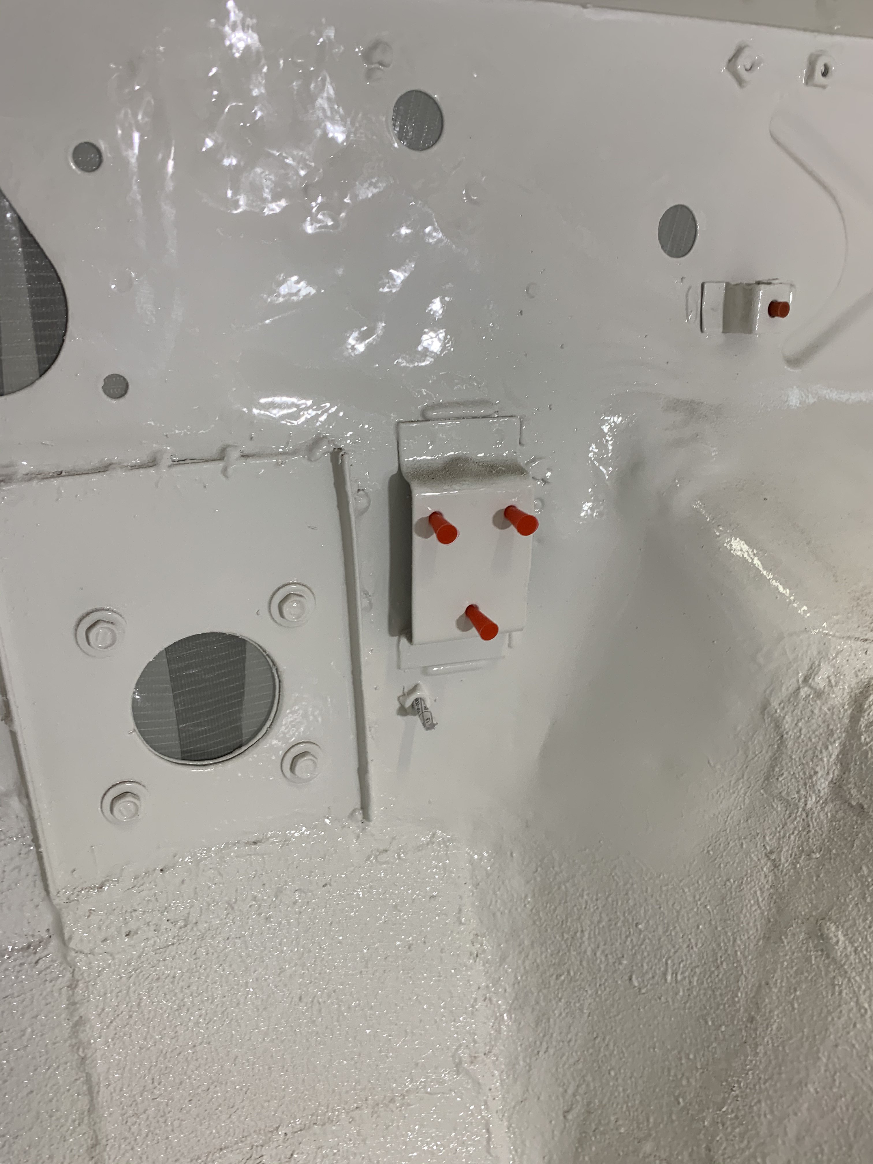
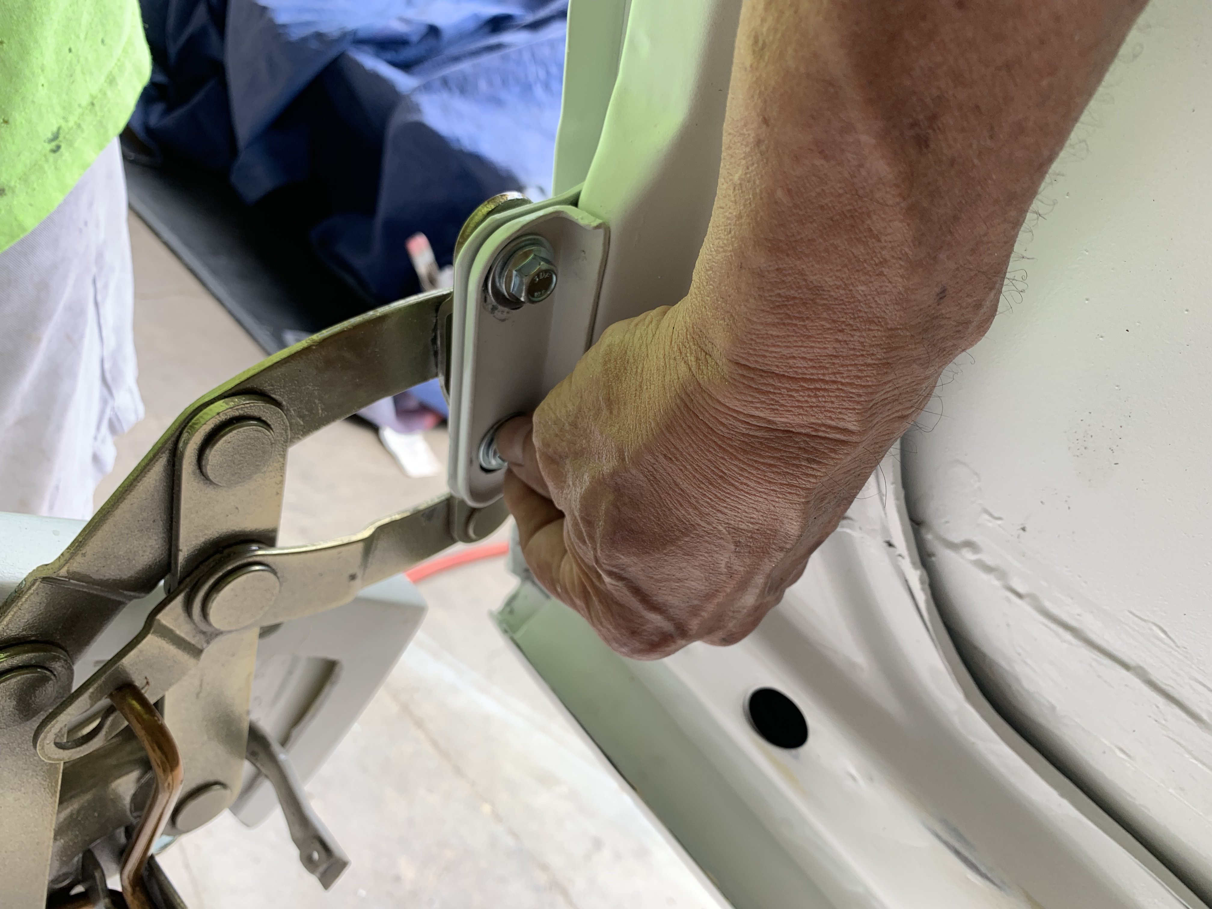
Threaded inserts-5MM -.8 were used to fastening the roof of the cowl vent. This will allow easy removal at a later date. 5MM-.8 stainless steel screws hold on the roof section. Finished cowl vent. The battery tray was finished using seven 8mm-125 stainless steel bolts and threaded inserts to hold it down. The four 1" holes in the frame rails were plugged by 1 1/4" white plastic plugs found on Ebay. A 1" clear plastic hose was inserted into the plug. This forced the plastic arms to expand outward and provided a tight fit. After installing the engine crossmember, I needed to replace the camber eccentric in them. Old ones were worn out. 69-70 Dodge Darts had similar ones. This is NAPA version of eccentric camber adjusters for only $25 for two. Locking nut side Camber Adjusting nut side This kit gives about Plus or Minus One degree Camber adjustment. Installation only requires slotting the bolt hole and a little welding. Next Topic is the Hood Hinge torsion spring installation. First, install in either hinge, all the three mounting bolts. On the other side hinge, loosely install only the mounting bolt on the hinge nearest firewall. Plastic tie was used to hold the first rod(one on the left] in stationary position and also hold the second rod with hat in the swivel bracket. The plastic tie in the rods center holds them place. Remove the loose bolt from hinge and move hinge assembly outward. This gives you more working area. I used a 5 gallon bucket to provide support of the hinge while twisting the second rod with hat. A strong twist is required to put the hat into the swivel bracket. Cut off all plastic ties. The finished installation. Left side strut and tension bar installed. I have not decided what coil over setup to use yet so using stock (except Progessive Coil spring installed) for now. Steering rack and stabilizer bar installed.


.JPG.618c03ca6859a3c800412e6cc9d8014f.JPG)


.JPG.bd6c0d05d8add7d96999edff187b8dc7.JPG)


.JPG.f8f7ec4dfdc6e3639faeca609c5781ad.JPG)


.JPG.4d4025e02ae6dd503f60ea22d30ad021.JPG)
.JPG.78d19281006a2cda203f36955b4d5d11.JPG)
.JPG.6da2eb7ddef33a1609e9ee44cac162ea.JPG)
.JPG.ec64356e02f289497b2a8d09b72af024.JPG)
.JPG.a1a9c59b9368731763fae5815afa014e.JPG)

.JPG.0222b3a86a6efbd3796ce0ad56594280.JPG)


.JPG.9c235801c954365c97b3920b004b92ef.JPG)

.JPG.635ec26f64860989f69157fe48d7b88d.JPG)
.JPG.8a1ae3e4fe3f635fe1a6961e53d2c5d8.JPG)


.JPG.911bbd50fb9d2dc2f4e9ca9887f56514.JPG)

.JPG.61d1503ef9013e3840fd5a64bc1cbf21.JPG)
.JPG.ec8dcf5fdc85eec9bad146088f078980.JPG)
.JPG.8c4bc6d951b83f5799e97903c5777c05.JPG)


.JPG.ffa28c10600a791d1a64bef5f3181d12.JPG)
.JPG.73b95fed9a7ec3323b4ca40c2fe08fa9.JPG)
.JPG.23b80d558c1581209f06be862d28bd34.JPG)


.JPG.9af81522be1cf46a2269d1ede5adf721.JPG)
.JPG.dec5b00b4966b521e23238b4d338425f.JPG)


.JPG.c67a43eb792b2bf2194a6ae471aa1cd2.JPG)

.JPG.cbceef87c868738d9e6574bce9df4a99.JPG)
.JPG.1104bc4ed4a602228113b355dec93ba1.JPG)
.JPG.0670071e525ed118fa3333e903c39dec.JPG)