-
Posts
357 -
Joined
-
Last visited
-
Days Won
3
Content Type
Profiles
Forums
Blogs
Events
Gallery
Downloads
Store
Everything posted by Snailed
-
When the heater control valve is closed (heat off) there is no flow, same as capping them.
-
Nice project SunnyZ. This looks like a very rugged upgrade. I agree on the Drive Shaft Shop too. Excellent company to deal with for custom stuff.
-
The EZ Wiring manual and support is pretty bad but pretty much all the GM based panels, and there are A LOT, are set up the same way if you want to find better documentation. For the money the EZ setup is a really good deal I think considering the quality of the wire. I find their markings a little vague but very legible. Try doing an older Painless harness if you like to squint, they are well labeled and mostly illegible. It's really not fair to compare a $180 kit to a 3 or $400 kit is it? I think you are only paying for tech support and the name with many of them.
-
I don't quite get why it's assumed that a turbo should spin at idle, but it's a question that you can find the answer to on pretty much any car forum. https://www.google.com/search?q=turbo+won%27t+spin+at+idle&ie=utf-8&oe=utf-8&aq=t&rls=org.mozilla:en-US:official&client=firefox-a It's funny how many threads are presented with such distress too. Lots of exclamation points.
-
We? Who calls them that? Does it say that in the Datsun manual or something? Google image search "driving light" and see how many parking lights come up.
-
I guess it's ok as long as you can stay away from the drugs and perverts. Doesn't seem worth it to me, but I'm sure you know what you're doing.
-
Yes, that's what I mean.
-
You can bend it over your knee, a bottle, whatever, it would be less than an inch wide, right? Something around 1/16" thick could have the edges sanded to a nice radius and then polished. It wouldn't have a full dome shape to it but it could still look nice if you do it carefully. I make SS trim this way sometimes and it works well. Do you have access to a bead roller? You could give the whole strip an arched profile by drawing the shape out on your flat sheet, bead rolling a wide bead between the lines, then cut out and finish. Another option to get the rolled under edges is using much thinner stainless and hammering over a form. It would have to be a collapsible buck since the part is continuous. Here is some windshield trim pieces I made for a '67 toyota 2000GT using this method.
-
This may not apply to the crank and pulley design on the L, but I'll throw it out there for review; On the V10 Mopar engines I have installed superchargers on I drilled two 1/4" holes, 180 degrees apart, through the pulley and into the crank snout about 3/4". Roll pins were then hammered into the holes. These are not keyed from the factory and most of them rely on a ~30mm bolt that is torqued dry (I believe) to 250 ft/lbs, which came loose on stock Vipers frequently anyway. I'm not sure if roll pins are the best way but I did it to six Vipers and they are all still together, some making over 1000whp. I have done this on a 6.1L Hemi also.
-
I would make the trim rind out of a flat sheet of stainless. It would cost a little more but the result would be much nicer since the shape would be molded to the car and there would be no seam.
-
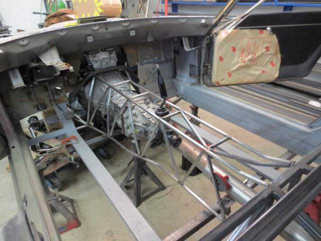
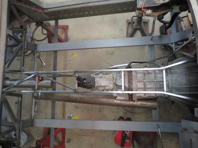
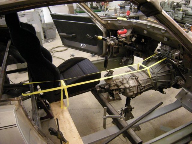
Here is the start of the tunnel. I mocked up the top panel out of 1/2" square tube with a .065" wall (6" wide by ~55" with no diagonals) and just that part had quite a bit more torsional rigidity than the entire stock tunnel I took out. The comparison was done using the step-on-it-and-twist-it testing protocol. It difference between the two was noticeable. I'll be welding up the whole thing on the bench so I hope to rig up a lbs/degree test to compare the two parts while divorced from the car. You can also see roughly how the exhaust will be run. The bottom of the exhaust in the tunnel will be flush with the bottom of the car, which is the height of the rockers and the 1x3 that runs under the seats. It will be very easy to have it tucked up all the way back with the slightly raised drivetrain.
-
Very nice power! Hows it feel on the street? Dyno graphs?
-
Thanks guys! It's been fun so far.
-

Sirpents 260Z / C32 AMG Powered RS30 - Australia
Snailed replied to Sirpent's topic in S30 Series - 240z, 260z, 280z
Surge setup looks good to me. I assume the picture isn't representing the locations of the tubes in the surge tank, only the routing. Headlights will be interesting. Have any mock up pics or drawings? -
Why are you trying to do by spraying water/meth if you are not out of fuel and it's not knocking anyway? If you want water and/or meth spray to work well, spray it in 6-8" before the throttle plate(s) or wherever it will give it some room to distribute more evenly (it won't but you can get close) but still as close to the combustion chamber as you can. If you want to see the wastegate solenoid pulse width go down, turn the boost down.
-
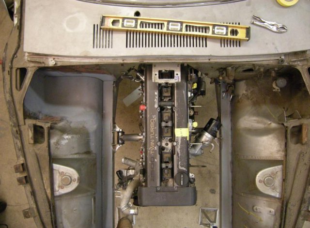
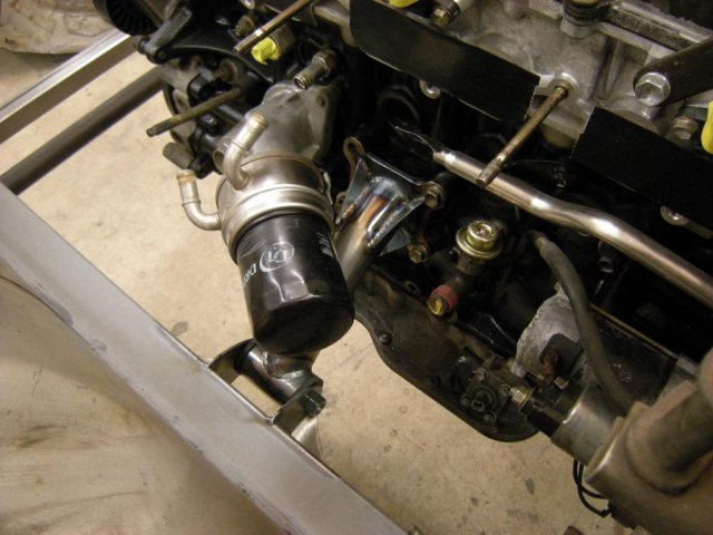
I got the engine mount brackets welded up. The big tube is the same as the bushing sleeve, 1.75" x .120" DOM. The gussets are 14g. The pair ended up saving 2lbs over the stock aluminum bracket and rubber mount. No huge lightness "gain", but at least I'm not adding more than it had. The bushings feel pretty soft, but I don't think I can rock the engine even a 32nd of an inch at the valve cover. Can't wait to see how they work when it's together. The tabs on the rails are made from 1/8" hot rolled steel. I think I will add some doubling plates around them and up onto the top out of 14g just to make sure they don't fatigue the 2.5" square tube. I think the steering shaft will just clear the tab on the drivers side, but I don't know the exact rack location (or even what rack) yet so that might get interesting. I'm getting started on the framework for the tunnel too. Somehow the stock shift lever is just about perfect even though the engine is back a bit. I can reach 1-3-5 without pulling my shoulder off the seat, and 2-4-R don't jam my arm into the bolster. The knob will be close to the steering wheel too, which just makes it easier to drive. The idea on the tunnel is to make it pretty strong in torsion without making it much heavier than the stock one. I already added a bunch of weight in the four lengths of 1x3 that run in the rockers and down the floor. In hindsight, I might have done that a bit differently so I could make the tunnel out of bigger chromoly tubing. As it is I'm just going to use 3/4" and 1/2" square tube and simplify it a bit. I will roughly follow a truss design and there will be four main tubes or chords and the middle will be filled with diagonal webs. It will be skinned with 22g steel. Beyond strength, design concerns include; room for plumbing/wiring up top, transmission cross member, heater box mounting, heat shielding for exhaust and room for seats. I'm open to suggestions on this project if you think I'm overlooking something or could improve my plans.
-
Ok, the back pressure was tested correctly where I assumed it wasn't. The setup described still sounds unlikely and not applicable to the goals of the OP to me. What is this compressor wheel that can flow 55-60lbs/min happily with a stock T3 on the other end? I suspect there is a reason beyond sheer ignorance a stock T3 turbine is typically abandoned after 275-300 hp.
-
I totally understand the strategy and agree with you and him on that. I was just pointing out that making use of more ba$ic techniques is very useful. A wideband O2 should be used with reading plugs and listening to the engine, not instead of IMO. I thought the winking face sort of implied my tone...damn internet.
-
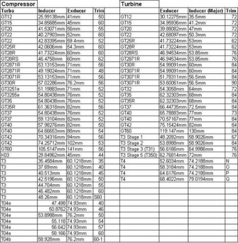
I don't know everything about them either. The sizing stuff is very basic and information you need to have if you want to swap around used turbo parts. I have taken more than my share of junkyard turbos out, rebuilt and reused them in custom turbo kits on other engines. I learned a lot taking them apart but I also realize how much I don't know. Here is a chart of Garrett turbo wheel sizes. Take off the compressor covers and measure the wheels. Bigger is better in this case. There are several compressor wheels that are fitted to OEM T3s. I would use the .63 turbine housing. On such a large engine, the difference in spool between the .48 and .63 will be negligible.
-
Tony, I like your personality and drive to share but you post is packed with misinformation. A .63 a/r turbine housing that fits a standard t3 turbine wheel (like all OE fitted T3s have and what the original poster is talking about) is not even close in restriction, power, size, anything, to a .63 a/r housing that fits a large aftermarket turbine wheel like a T31(stg3) or t350(stg5). It's just not relevant what the turbine a/r of a 500+hp turbo is in relation to a stock T3 from a Ford, Saab, Nissan, etc... And beyond that, when the system is at full boost you are not measuring the restriction of the turbine wheel and housing combination since most of the exhaust is going out the completely OPEN wastegate. A/R is a teeny tiny fine tuning thing compared to wheel size and is not comparable in any way if the wheels are different. Your turbo size is never printed on the outside of it. You need to know the what wheels are in the turbo(s) to have an intelligent conversation comparing turbos even though a lot of people think the stampings on the covers are comparable and insist on referring to those numbers as "trim" as if they have anything to do with how much air it can flow. This is the same lazy information processing that leads people to think the aspect ratio number on a tire is comparable without knowing the width of the tire. [dumbass voice] "Hey is says 60 right here and that's bigger than 50 so it must be a taller sidewall!" when one tire is a 205 and the other a 295.
-
So even if it's a smaller compressor wheel you are concerned with fine tuning the turbine housing? Backwards.
-
You might find shrugging and then reading the spark plugs a little more effective for individual cylinder trimming. That's what us kids with only one WB do.
-
The wheel size is not printed anywhere on your turbos. People just lazily refer to turbos by whatever it says on the cover (a/r) but it has nothing to do with what actually matters when you are trying to replace or upgrade a turbo. Don't trust what people say about a used turbo. Measure it. The trim of the compressor or turbine wheel is a relationship between it's inducer and exducer measurements. Measure the wheel dimensions on your new one and see what you have in comparison to the old turbo. The A/R printed on the housings is not related to what wheel in inside and has little to do with how much power it can make. You need to measure the wheels directly to figure out what they are. There are all kinds of turbo wheel charts available with a little searching.
-
To get the most useful reading I would try to put it in a spot where the gases from all four cylinders have completely mixed. So if it's going in the collector, put it as close to the small end as practical. Also make sure the tip of the sensor is angled down so moisture doesn't collect in it.
-
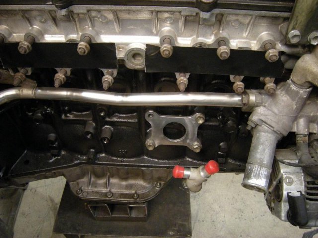
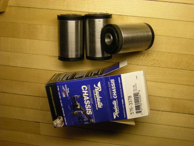
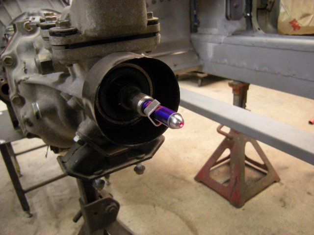
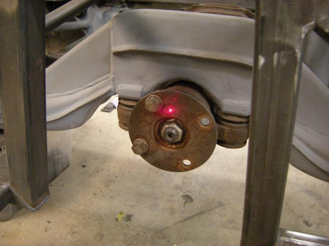
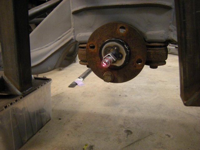
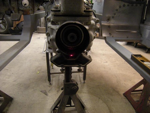
The engine and transmission mounts are up next. The factory engine mount brackets are a pretty excellent design but I don't want to mount the engine to the suspension subframe. I'm going to use 1.75" DOM tube and bushings attached to tabs on the frame rails. I believe mounting the bushings close to the frame rails should give me the least idle vibration with the most resistance to engine movement from Tq and shock from shifting for a given durometer. I made the the plates that bolt to the block out of 1/4" mild steel with a 1.75 ID hole in the center. I tried to make them as light as I think I can get away with. There will be gussets to try and get the bending forces off the mounting plate somewhat. I decided to start with rubber bushings because I think they will still be nice and stiff while absorbing a little more vibration than most poly bushings. I spent some time looking for OEM bushings that will press into standard DOM tubing sizes and I found the leaf spring bushings for a '91 Isuzu Rodeo fit a 1.75" x .120" wall nicely. They are about $4 a pair for the higher grade Raybestos rubber ones and poly bushings are available if I change my mind later. The outer sleeves are just a piece of scrap DOM that I cut to length and cleaned up on the lathe. I figured out a cheap and easy way to make the inner sleeve too. 3/8" sch 40 pipe is the perfect OD to fit the bushing and the ID is good for a 12mm bolt. I bought a 12" galvanized pipe (needed 9") from the hardware store for $5. I have engine position almost perfect but I want to refine it a little more before finishing the mounts so I made a couple holders for a $5 laser pointer. I bought 2 of the pointers but one of them was so out of alignment I couldn't use it. One holder just threads into the output shaft of the transmission and the pinion one is a magnet for the base. The pointers are carefully pressed in and then bent into alignment until the red dot does not move when the shaft is rotated. I saw this on some forum (here maybe?) and always wanted to try it.


