Boy from Oz
-
Posts
541 -
Joined
-
Last visited
-
Days Won
2
Content Type
Profiles
Forums
Blogs
Events
Gallery
Downloads
Store
Everything posted by Boy from Oz
-
Eric - good to have you back, I always look forward to seeing what you have done. Keep the photos coming.
-
If we didn't have a sense of humour we would never persevere with these builds.
-
Crikey, Wes, that’s just about the dumbest thing I’ve seen written on here. I don’t want to turn this into a self-effacing competition and I bet if you looked at our two cars in the metal (+ fibreglass and filler) there wouldn’t be much difference. You’ve actually sat in yours and driven it; after seven and a half years and a pot of money mine is, today (that’s tomorrow to you!), on a rotisserie. I know which car I would prefer to have right now. Regards.
-
Excellent, Wes. Wish I knew that before i started. If there is an overcomplicated way of doing something, fear not, I will find it!
-
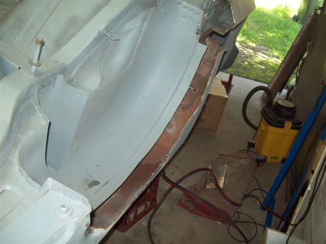
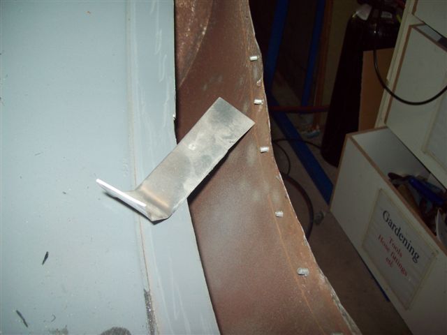
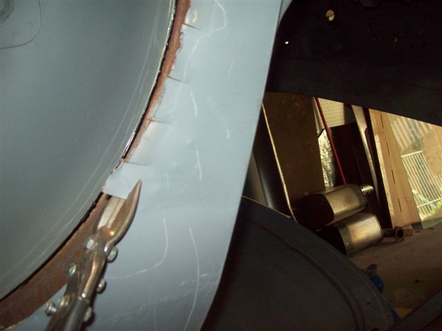
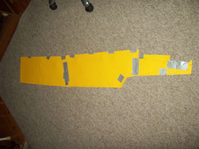
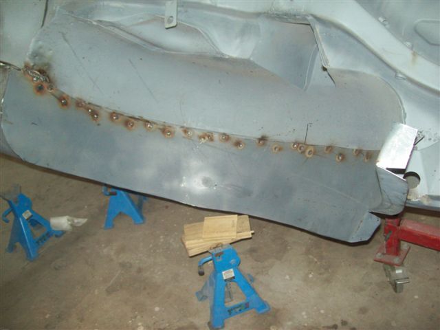
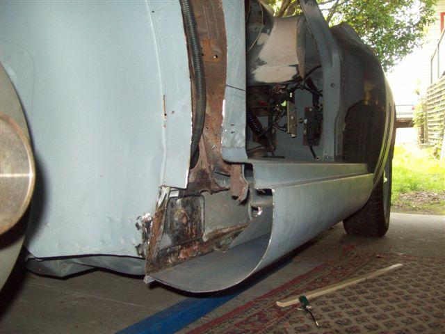
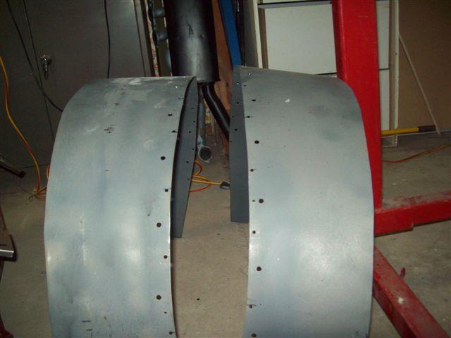
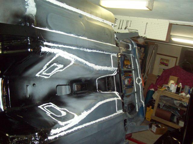
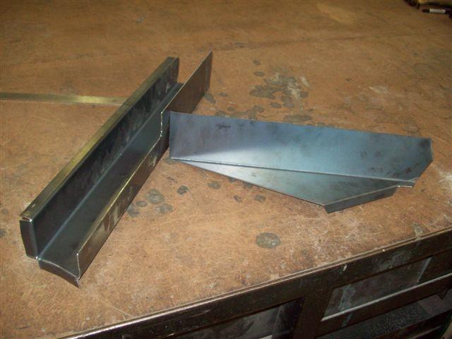
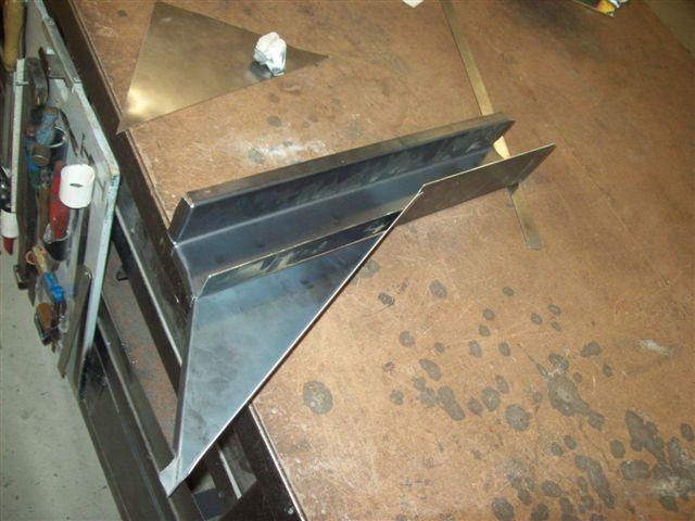
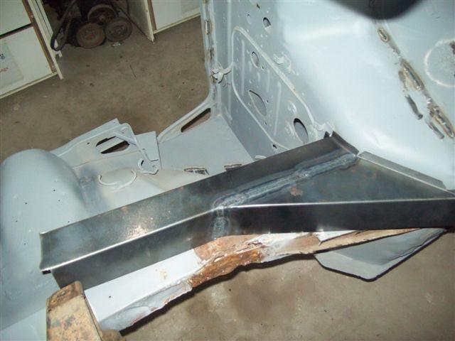
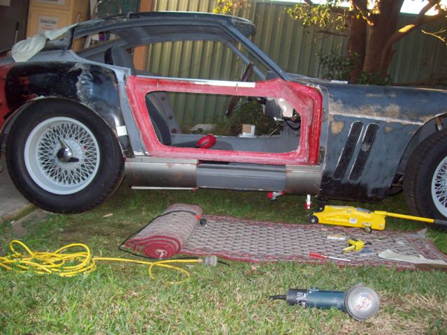
That's not my car, sorry I can't help There was no template with my second-hand Puckett kit but here's how I went about it. There would be no point in using a Puckett template unless you had a Puckett. The process outlined below could be followed for any kit - I think! I marked out and cut the tub 50mm from the centre join line. I used a bit of 'L' shaped scrap metal to scribe a line on the inside of the quarter panel, parallel to the arch of the tub. I cut the quarter panel along the line. I temporarily located the fibreglass rear section.in position. I cut a cardboard template to the shape of a new tub. I made a strip of sheet steel to the shape of the template and drilled welding holes and then curved it by hand - not hard. I fitted the new tub extension and welded it in position via the pre-drilled holes. I am in the process of attaching vertical sheet metal panels to the tubs which will provide a surface which will glue to the fibreglass section on final installation. I did most of the work whilst the car was on a rotisserie so some of the images may appear upside-down - but that's what we Downunder are used to!

-
Trevor - Thanks for that. I managed to track down a couple of Puckett owners and I have a copy of the Berlinetta manual - for what it's worth. It appears Mr Puckett had quite an engineering flair but his management skills left something to be desired - pity, it's a great looking kit.
-
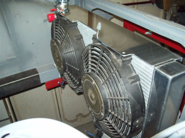
I had a radiator made that was 50mm lower. I then made a cold air intake to fit over the top with a standard rectangular filter facing downwards and also an alternative shape which would sit behind the radiator. I'm undecided which I will use. Check the Aussie eBay for OTR intakes - they are a very popular aftermarket item down here for LSx powered cars.
-

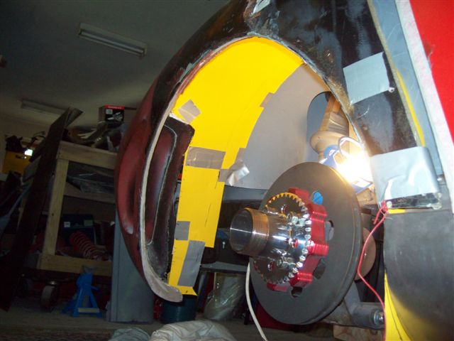
GM LSD IRS diff in S30 - fits like a glove.
Boy from Oz replied to Boy from Oz's topic in Drivetrain
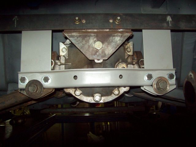
Can't believe it has been so long but a heart attack and work on other aspects of the project delayed finalisation on the diff installation - but here it is. -
-
Or you could do a ragtop.
-
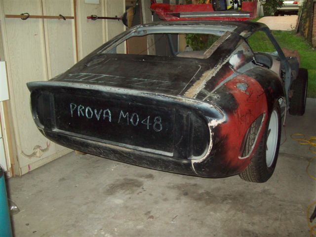
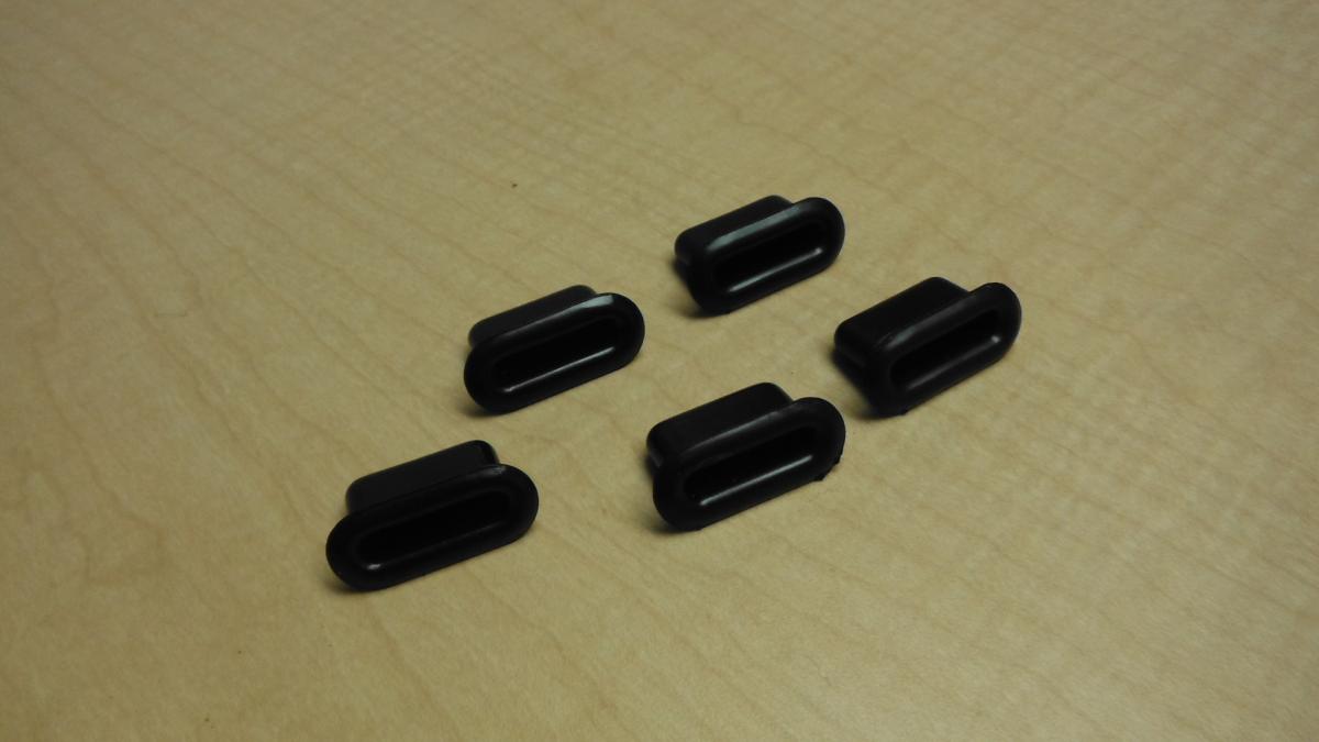
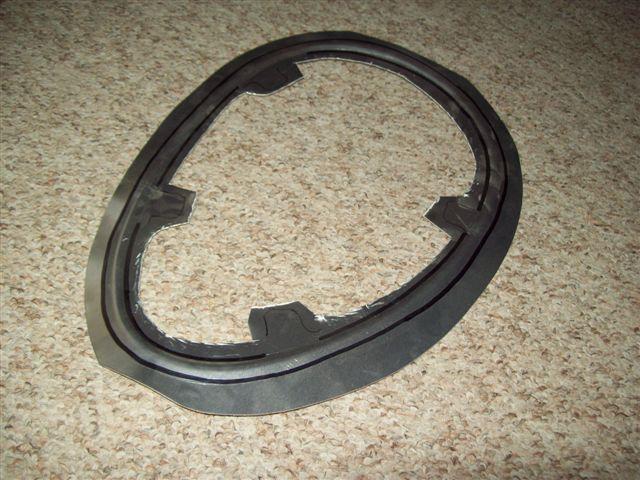
Those slots are fitted with rubber inserts and there are five corresponding tongues on the OEM cowl which slip in as part of the cowl mounting process. I think I'll probably go with adding 15mm or so to that edge - first thoughts! I've attached a photo of my old kit showing no cowl and one of a friend's car with it fitted. An issue I see with this approach is that the bonnet (hood to you) needs to have a back edge profile to match the OEM cowl.
-
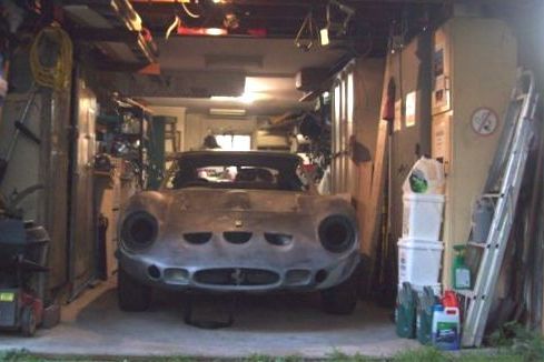
Ken – I’m not sure exactly what you mean by ‘windscreen vents’, perhaps a photo might assist on that point. I think I’m going to have a similar issue with the ‘Puckett’ kit and I will be using fiberglass to build it up rather that body-filler – I know filler is pretty impressive stuff these days but I prefer a good thick fiberglass edge. Is the windscreen in your car? I took a long time to detail fit my Simpson dash (John Washington), including converting to RHD, only to find it interfered with the windscreen rubber, so make sure the windscreen seal is fitted if you start to modify in this area. My first kit (make uncertain) retained the original cowl so is it possible to cut away the fiberglass cowl on your kit and replace it with the OEM as an alternative approach? … Just a thought.
-
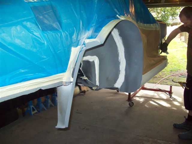
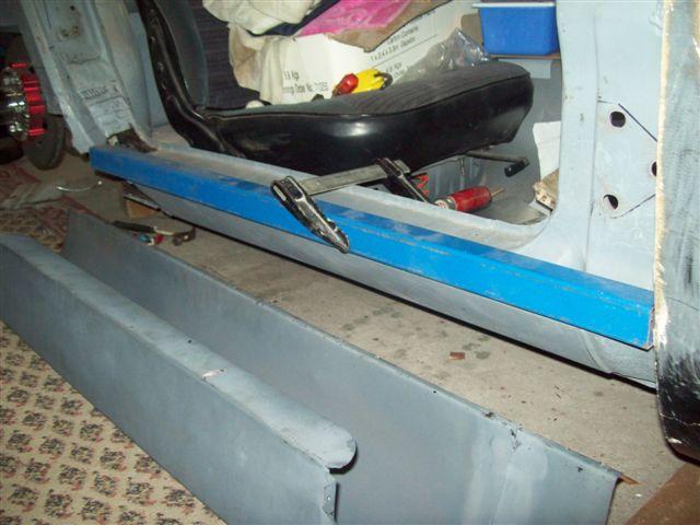
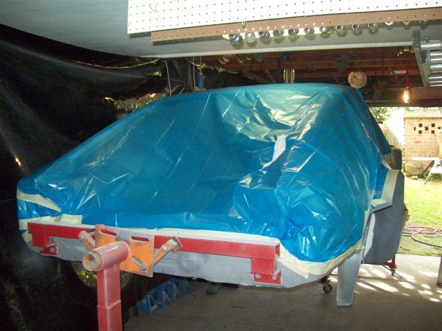
Great to read some activity on this thread. Congratulations to the folks making progress. I’ve been doing my bit – the wider tubs and rocker panels are finally installed, including 'stiffening brace', and I’ve got the engine bay and interior painted, plus the stonechip applied.
-
LSx s30 Longtube group buy thread
Boy from Oz replied to 1 tuff z's topic in Gen III & IV Chevy V8Z Tech Board
No, not a problem (see image). I'm using the JCI mount. The odd shape was to ensure the primaries were all the same length, or as close to as possible. Also, my brake booster and clutch m/c are on the other side. -
LSx s30 Longtube group buy thread
Boy from Oz replied to 1 tuff z's topic in Gen III & IV Chevy V8Z Tech Board
Have just taken my LS1 out and placed it in the cradle. I've attached MY headers to show an image some may not have seen before. I think your passenger side (my driver's side) is very similar and there is probably not much difference on the other side. -
You need to think carefully about this. . Even back in the Seventies engineers were designing collapsible front ends which are designed to ‘save’ the cabin. The engine and transmission are designed to slide under the cabin and take the frame rails with it, or for them to crumble and absorb the energy. Stiffening a chassis (unibody) might be great for racing but don’t have an accident. The thing you need to remember is that a relatively minor bump may crumble the rail and a panel (repairable) but if you alter the design characteristics you may find major structural and alignment issues occur from even minor carpark knocks. I just replicated the original design.
-
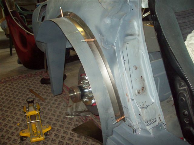
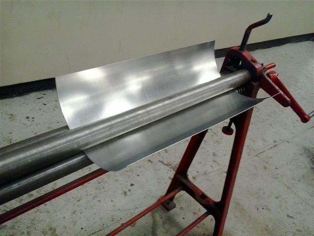
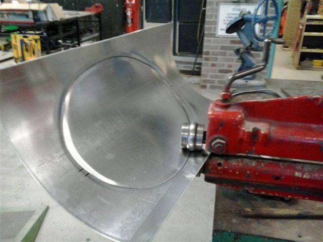
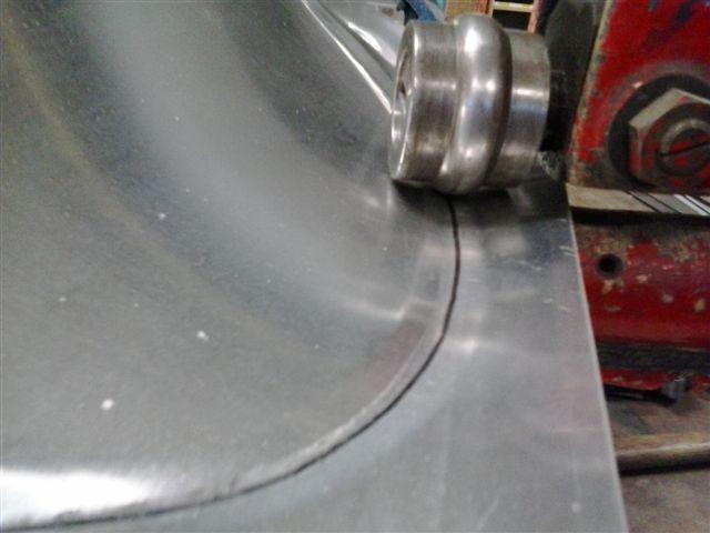
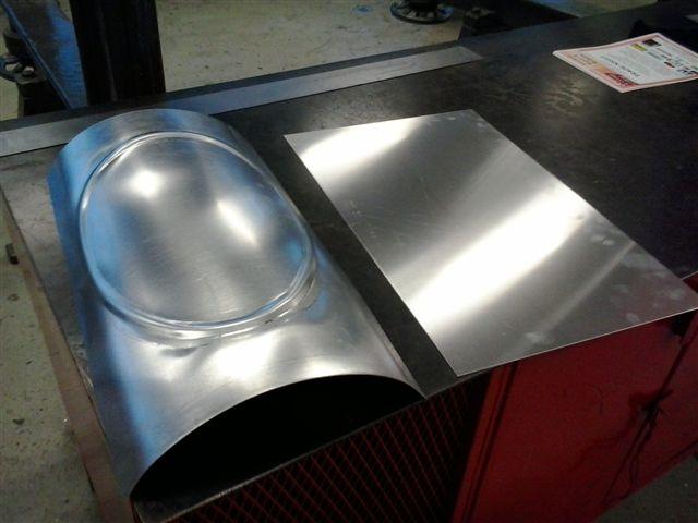
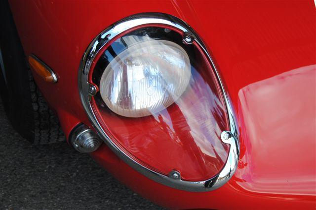
I thought ThunderRanch had them but here is how I made them. Any sheetmetal fabrication shop should be able to made them for you. You need the lexan covers to use as a template. 1 Curve the sheet (I used aluminium) (edit). 1.0mm thickness. 2 Use the headlight cover to mark the centreline. 3 Use a swage tool to create the dome form 4 Mark out the securing tab locations. 5 Cut out. 6.Carefully trim
-
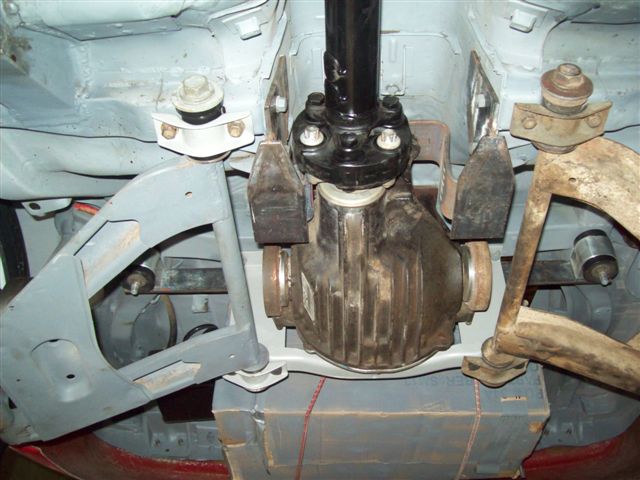
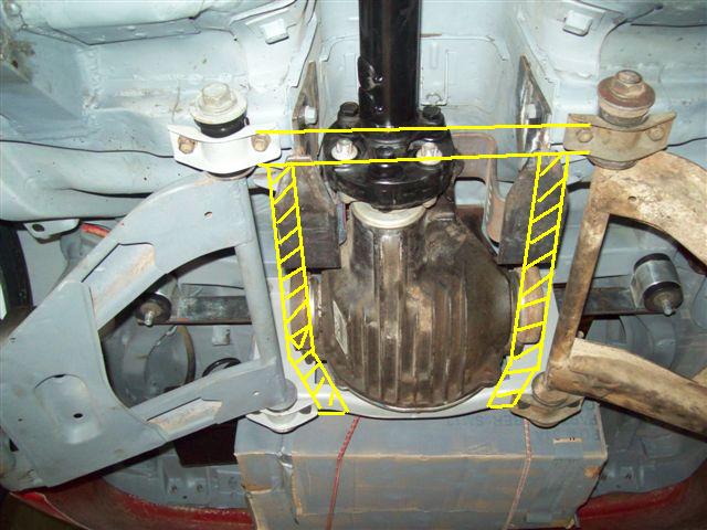
Just make sure you have clearance between the universal and the heads of the bolts securing the front mount to the transmission tunnel. I have a jurid coupling and it's very close as the pinion shaft is 25mm off-centre. (edit) Ignore the mounts, they were a first design attempt and long since discarded. The photo is to highlight the tight clearance.
-
Look up the 'FAQ' - 'Body Kits and Paint' - '250 GTO Owners' thread. I think ThunderRanch and Reaction Research are the only two available now.
-
I welded several sleeves into the rails (not Bad Dog) for a gearbox mount. You might want to consider this approach for a cross-member or tailshaft hoop as well. It gives you the option to use them or not and you can change the design to suit any drivetrain or exhaust system.
-
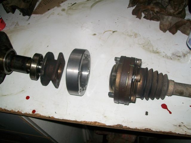
How long are the GM CV shaft assemblies? 510 mm Did you have new shafts made to fit,...? Yes, 345mm, and quite expensive! The GM shafts from my donor car had one fixed and one floating CV. The high performance GM cars have two floating CVs so I'm having a shaft made with the spline for floating CVs on both ends. The Pontiac GTOs may have two floating CVs.
-
I think it will lose traction before anything breaks. I'm building a 250 GTO and I'm fitting narrow (7") rear rims with skinny tyres, for the period look. The high aspect ratio tyres have a 29" dia.
-
There are a couple of S30s in Oz with GM IRS diffs (i.e. Pontiac GTO and G8 to you). Each is quite different in how they are mounted but here are a few thoughts about both which might assist. Use an adaptor plate from the diff cover to new or existing moustache bar, or Weld a block of aluminium to the cover and drill and tap new mounting holes. Modern diffs a nearly always much much shorter than S30 ones so the front mounts are difficult to design. I initially made some cantilever brackets but I am abandoning that set-up in favour of fitting twin support rails running from the rear diff cross-member to the front diff cross-member (the one with the exhaust cut-out). I have removed that cross-member but I shall be refitting it with the new set-up. I can’t show you photos of the new set-up but I have added the rail to an old photo to illustrate the point. There is insufficient room for straight rails so you either have to bend round tube ot notch out some rectangular tube. I have also machined an adaptor for the GM CVs to Datsun outer stub. Hope I haven't confused you.
-
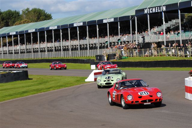
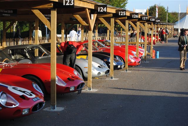
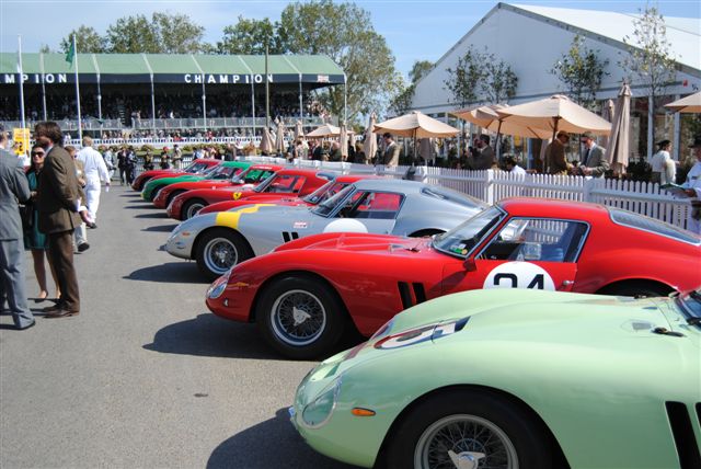
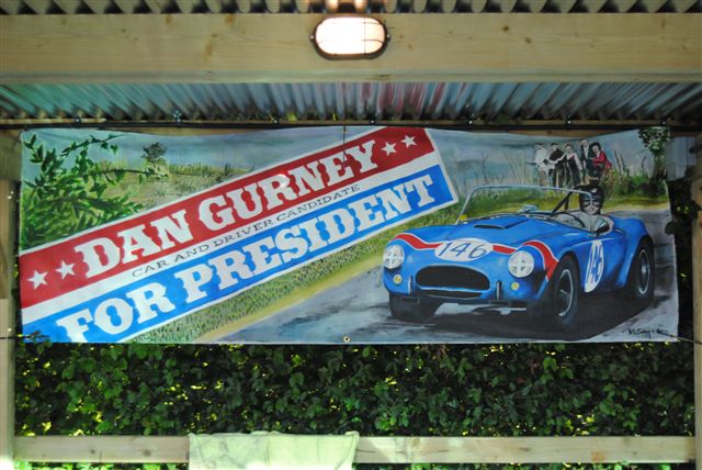
I attended the Goodwood Revival last month where there was a special event to celebrate the 50th anniversary of the 250 GTO. There was also a special tribute to Dan Gurney.
-
It was not a 'how to' manual but rather something I put together to show the authorities what I was proposing to do so I knew I could get it registered when it was finished - I thought that would be 3 years but that was nearly 7 years ago! The registration requirements down here are very tough - think California and then multiply by 2. If you send me a private message with your e-mail I'll send some sample files and you can see if they are of interest.