

RTz
-
Posts
2943 -
Joined
-
Last visited
-
Days Won
23
Content Type
Profiles
Forums
Blogs
Events
Gallery
Downloads
Store
Posts posted by RTz
-
-
The simple answer to your question is yes, you can regulate the stock EFI pump down. BUT, the stock pump is built to recirculate... if you allow it to dead-head, it wont survive. Those common non-recirculating carb regulators are a no-no in this case.
-
Yes, I was informed WB functionality is ready.
I have some questions on implementation so we're discussing details.
-
What I've learned by doing a few of these kinds of things (in Miatas, FD RX7s, 240Zs, and E36 BMWs) is that, with proper reinforcement, its really not an issue. For the 240Z, welding the OEM front crossmember in place and reinforcing the frame rails between the TC box and the welded in crossmember adds a lot of support in that area. I also, in the front wheel well, weld in plates that connect the reinforcement where the crossmember mounts to the reinforced area on the wheel well for the strut towers.
I agree. If an engine is frame mounted with suitable reinforcement, I can think of no significant drawback.
-
1mm is just under .040"... the size of a healthy sparkplug gap. There's probably more variability than that from one chassis to another.
-
It can be done easily!!
Git 'R Done

-
Seems to me that as the suspension compresses the longitudinal link will cause the suspension to swing in an arc.
Could be used as anti-squat?
That would very quickly cause bind in the lateral links, if everything were solid bearings.
Got it, and I agree. I had assumed your were referring to spherical bearing's. I don't believe there would be any binding with spherical's.
EDIT--Actually, maybe that would just cause toe change. Still not what I'd be looking for.
Subtle use of toe changes are often desirable. I probably would'nt go far out of my way to have dynamic toe, but I'm not opposed to it if 'comes with the package' and the curve is reasonable.
The RCVD book discusses this suspension on p642 as well. Binding is not mentioned as an issue with this setup, although toe change is and it's suggested as a good suspension design for compliance and ride comfort.
It does say something to that effect, but its related to bushing orientation/durometer, which wouldn't be applicable here.
I'm 'arguing' simply becuase I see it as a reasonable alternative and based on similar packaging. Unfortunately, I'm not conviced of the strut side load's being a factor that can be reasoanbly reduced with control arm design, but its outside my ability to either argue or prove.
Am I bugging you yet?
-
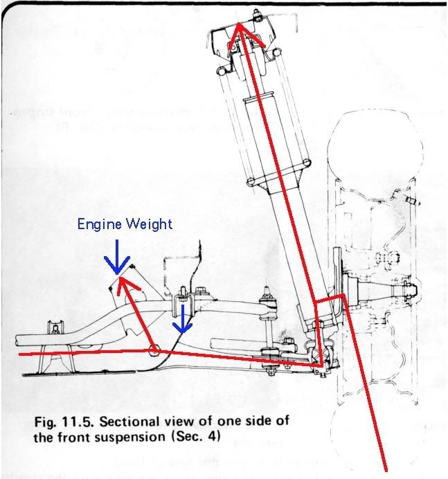
Engine mass loads, when mounted to the crossmember, pass directly to the suspension. The same would be essentially true if the engine mounts were on the frame rail directly above where the crossmember mounts to the frame rail. Moving the engine mounting back on the frame rail makes the frame rail more of a beam connecting the front suspension with the engine mounts.
Perfect! That's exactly it. I need to learn how to write.
-
I fail to see the Subaru's relevance.
No effort to control strut side loading.
Replace all the bushings with bearings and then we could talk about binding issues.
I'm game, lets talk. If all points where replaced with spherical's, what binding would there be?
-
Just 'cause I enjoy playing devils advocate from time to time
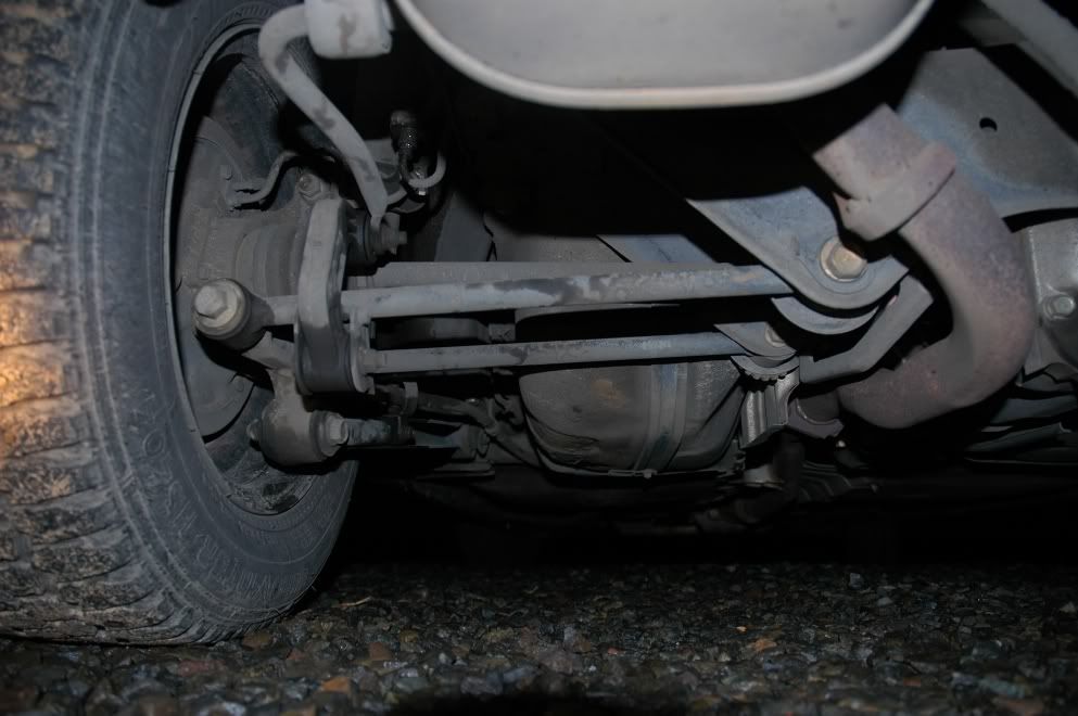
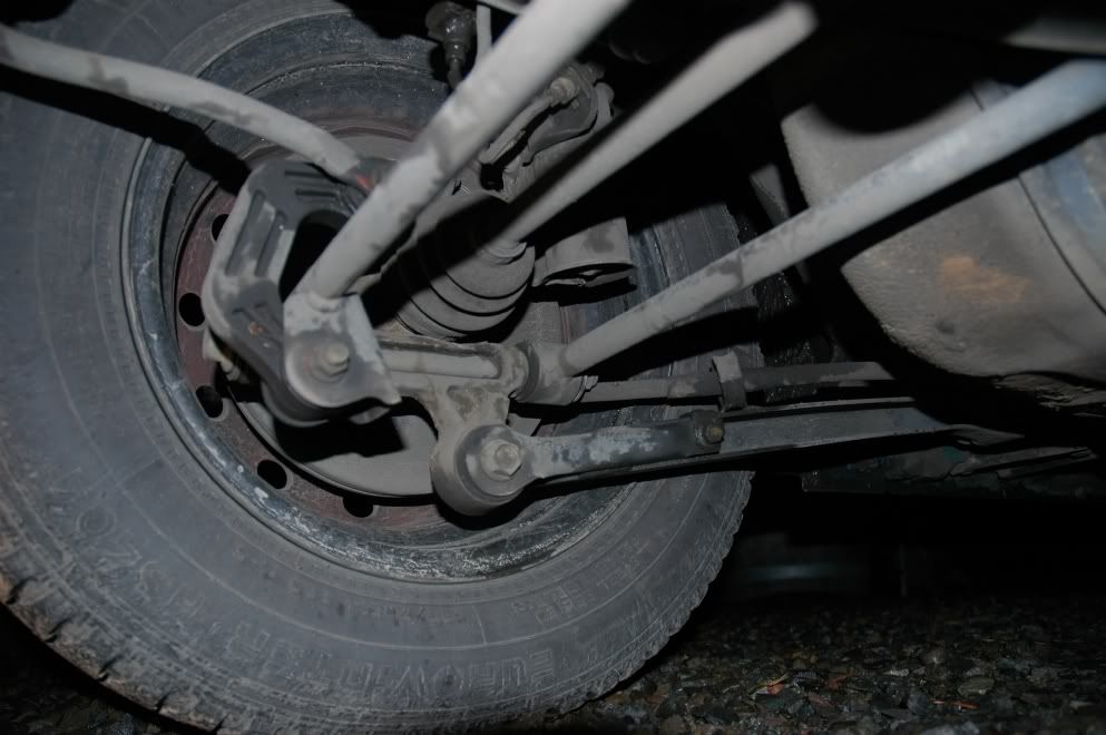
...These are of the rear suspension in my wife's Subaru sedan. Two lateral links and one longitudinal, completely independent of each other.
-
Jon, I'm thinking the side loading is caused by the difference between the wheel CL and strut CL. The location of the pick-up point is going to have relativly little effect, I think
-
-
where does the engine move place the transmission shifter?
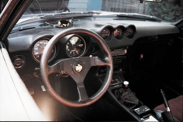
Here's a picture of my LT1 powered Z, also with a T56, mounted in the standard JTR position...
Its a modified Datsun shift lever, oriented so the offset positions the knob rearward. While its not etched in stone, its looking like the trans will be another 3" farther back. Flipping the shift lever around, I should end up with a knob an inch or two father back than the above picture, which I would welcome.
-
I'm not being argumentative, I'm just confused.
That makes two of us, my friend. I read your arguments as constructive and I'm hoping that you're doing the same with mine. I think there's value in understanding loads and load paths so this discussion interests me. If I prove to be wrong, so be it. I will walk away with a better understanding.
1. That a more direct connection between the contact patch and the engine has an effect on handling?
Nope, sorry to give that impression.
2. That a more direction connection between the contact patch and the engine has a greater or lesser effect on framerail loading?
Getting closer.
I thought presenting the case from a lateral perspective would have been easier, but thats not proving true. Allow me to start over from a vertical perspective, from the point of severe bottoming out.
To exaggerate, put 20,000 lbs of weight on top of the engine (stock mounted). The suspension will be on its stops and the four vertical bolts through the crossmember will try to tear out (vertically). The lower rail is seeing a lot of focused stress (in tension), but its being held to great degree by the upper rail due to the strut tower. A fairly robust load path.
On the other hand, assume the engine is mounted to the lower rail, roughly in the middle. Again, putting the same 20K lbs of weight on the engine. The suspension is still bottomed, but now the lower rail is bowed downward because the only thing attaching it to the upper rail is the inner fender and its not efficiently built for that load. Also, there is no longer ANY stress on the 4 crossmember bolts. In fact, you could remove them and move the crossmember up and down by hand. The load path changed.
In both cases the amount of stress is the same, but its re oriented. The loads on the rail changed from tension to compressive and the loads on the crossmember are removed entirely.
In retrospect, laterally speaking, its more complex, but still has the same 'issue'... a re-arranged load path.
If any of that makes sense, and you agree, I'll take another stab at the lateral scenario.
-
Also with the resulting weight percentage being almost 50/50 with the jtr mounts and driver included' date=' what's the point.
[/quote']
Some people aren't convinced 50/50 is 'ideal'... Porsche, Ferrari, myself...
-
Another possible way to look at it... Because there is a direct link from the contact patch to the crossmember, when you turn the wheel the crossmember (carrying the engine) moves laterally. The only reason the chassis follows is because of the four crossmember bolts, and to a lesser degree, the TC rods and upper strut mount.
-
The starter relay, in this case, is integral/synonymous with the starter solenoid. A generic Radio Shack part isn't interchangeable
-
-
Hi John,
I'm not trying to say the loads disappear... just trying to say they get re-arranged.
With a crossmember mounted engine, in a lateral load, the load goes from the contact patch, through the spindle, strut housing, BJ, LCA, and into the crossmember, which is directly connected to the engine. The lower frame rail sees no direct lateral loading. Yes, a 'small' amount is feed into the TC bucket via the TC rod, and a smaller amount yet throughout he trans mount. Its dispersed. Obviously, there is a direct load going through the upper spring perch and into the upper rail which shares the load with lower frame rail via the strut tower itself and the inner apron. Again, I see the loads being dispersed, and having no direct impact to the lower rail, except that of being pulled down.
Edit: My only point is that frame mounting will produce highly focused loads on the rail (instead of the crossmeber), whereas crossmember mounting disperses the loads over a broad area of the unibody
-
You little shi....
-
Why? The front frame rails are strongest at the TC rod buckets, which handle greater loads then the torque an engine can produce.
When the engine is mounted to the frame rails, the frame now sees a localized load point in every direction (lateral, vertical, longitudinal). When crossmember mounted, there are no lateral loads (from the engine) and the remaining loads are dispersed broadly through the upper and lower frame rails and inner fender liners.
Additionally, moving the mount 'pedestal's' back 5.5" isn't close enough to the TC bucket area to have any relevance, or so it seems to me.
Of lesser importance, an unnamed member has done some compliance testing of the bucket area, and has found, with 'normal' lateral chassis loading, there is quite a bit of flex in the TC bucket. While it may be the strongest part of the front frame rails, it still flex's more than I'd like to see.
I'm aware that a number of our members have done 'frame mounts'. Its simply my preference to avoid it if its reasonable.
-
I ordered...
At only $50.00, its not much of a gamble... we'll see how she fits up
-
Why not just cut the original motor mount brackets off and move them back 2 inches or do away with the JTR setback plates and move the original motor brackets back even further?
I would prefer to mount the engine to the crossmember. The load paths of frame mounting don't really excite me.
-
-
Possibly use mounts off the “front†of the block, using some isolator in the OE Datsun cross-member?…
Now I hadn't thought of a front mount. Hmmm... gotta look into that.
This one is catching my eye...
... looks to be stout enough longitudinally as well.
Thanks!


GM TBI (15psi) - fuel pressure and pump Q
in Fuel Delivery
Posted
Yes.
Yes.
A few items...
1) There is a '15 psi' regulator built-in (red circle)...
Supply on the left, return on the right.
2) The only potential issue that I see is the size of the return side. It needs to be large enough to flow all unused fuel at low demand (such as idle). The internal orifice's are pretty small, so it may take a little massaging to make that happen.
3) The regulator is nominal at 15psi, but this specific regulator is 'all over the place'. It will probably require some attention simply becuase I think your potential HP out ways the flow capacity of your injectors.
4) Which brings us to... which injectors do you have? The most common ones I see are #5235206. See red circle...
Those are rated for 55lbs/hr at 13 PSI
The 9C1 police cars came with 65lb/hr at 13PSI
There are several others if you dig.
5) I understand all these Rochester injectors are perfectly happy at 30-32 PSI. And some of them are good to around 70 PSI.
I see no reason you couldn't take the stock Datsun regulator and piggyback it on to the GM regulator (essentially overriding it). 36-38 PSI *might* work just fine with those injectors, and you're probably going to need it.