billseph
-
Posts
125 -
Joined
-
Last visited
Content Type
Profiles
Forums
Blogs
Events
Gallery
Downloads
Store
Everything posted by billseph
-
Turbo Swap, No Spark..What's Not Hooked Up Right??
billseph replied to billseph's topic in Ignition and Electrical
Nevermind, answered my own question with a no...the e12-80 ignition module is NOT at all going to work. Anyone got a working ignitor/coil bracket they can let go of...I gotta get this thing going. -
Turbo Swap, No Spark..What's Not Hooked Up Right??
billseph replied to billseph's topic in Ignition and Electrical
Very nice link NewZed...thank you. I'm about 1hr away from any JY's (I'd be going to north Bakersfield, CA or south to Lancaster/Palmdale CA...I'm about 1 hr. from both). I guess if it comes down to it I know what cars to look at now. Just thought of something after I saw the compatible vehicles on that link...will my e12-80 ignition module mounted on the n/a dizzy that had been in the car work??? It's got a T plug to plug into and a green and a red wire coming out of it into the dizzy. What do you think NewZed??? You're like the electric guru around here. -
Turbo Swap, No Spark..What's Not Hooked Up Right??
billseph replied to billseph's topic in Ignition and Electrical
That driver looks cool and would work I'm sure, and for less than $10 it would be very cool if someone could get it to work and show us all how to do the mod. However for me, this is one of those situations where I just need to pay up for "plug and play" since I'm a rookie. Maybe one day when I've got it all running properly I can experiment with this...but that's a BIG maybe -
Turbo Swap, No Spark..What's Not Hooked Up Right??
billseph replied to billseph's topic in Ignition and Electrical
Thanks for the reply cgsheen. I went ahead and checked power to the CAS (popped the cap, rotor, and cover plate off the dizzy to check internally)...it got 12 volts...also checked continuity back to the corresponding ECU plugs while I was in there...ALL GOOD. So CAS checked out OK. I checked voltage off the blue wire coming out of the ignitor that would connect to the coil -. Without the blue wire being connected to the coil I got about 1.0 volt with key in "on" and 0.9 volt while cranking. With the blue wire connected to coil - I got 12 volts with key in "on" and around 10.5 volts while cranking. Should I be checking amps or milliamps instead????? Sooooo, after these tests I'm leaning toward BAD IGNITOR...any thoughts. (Also I have cleaned all my connections...have good connections back to ECU for TPS, Air Regulator, Injectors, and CHTS. Buy really none of these should influence SPARK...just the ignitor and CAS, right???) A little background too.......I bought the car off some dude who'd swapped in the 81 zxt motor already...he went by the name Krumm on this site. He had trouble getting spark as well and suspected a bad CAS (crank mounted) so he swapped in a n/a dizzy (3rd page of the good ole' turbo swap into S30 sticky) to "make" it work. This leads me further to suspect a bad ignitor being my (our) root issue with spark. Anyways, now I'm trying to get this swap working PROPERLY so I can swap in my JWT 450 modded ECU. Maybe someone can be so gracious as to run these same tests I just have, or give me pointers on verifying a properly functioning ignitor. I'm so close I can taste it but this "lack of spark" issue has been a huge bummer. I think I'm gonna have to drop the $100 and get a coil/ignitor from the classifieds here on HBZ, but it'd be nice to get confirmation from someone with a zxt or a working swap. Thanks for listening guys...good thing is that all these headaches will just make success so much sweeter!! -
Turbo Swap, No Spark..What's Not Hooked Up Right??
billseph replied to billseph's topic in Ignition and Electrical
Thanks for the advice there, but I need to get SPARK. I've just got a #3 plug pulled attached to the spark plug wire so I can see if it's sparking. Only sensor not hooked up is knock...but this shouldn't affect me getting spark. -
So I'm working on getting my 81 L28ET swap into my 71 S30 going. Getting Fuel has been no problem...I've got power to fuel pump relay for 5 sec. In on and while cranking via pin 16 from ECU...also injectors seem to be working snice they're flooded with fuel from cranking with no spark. Anyways I've got no spark as the title says...I swear it's all hooked up right, but it obviously must not be or I've got a bad component somewhere. So here's the facts..... Pin 9, 27, and 35 all have power in the ignition "on" position and while cranking...GOOD?? Coil + and - have 12 volts in ignition "on" position...seems okay right?? Black/white strip on ignitor the "top of the "T" on the T plug, goes to 12 volt switched Yellow/white strip on ignitor the "vertical on the "T" on the T plug, goes to the yellow/white wire of the ignition harness plug (goes to Pin 5 of ECU as it should) There was a blue and a black wire coming out of the ignitor I have...they were just cut off by someone else, so I ran the black wire (which had 12 volts when T plug on ignitor is plugged in) to Coil +...SOUND RIGHT?? I ran the blue wire to Coil - (it has no power no ground) if it's just left hanging loose. Ignitor/coil bracket are verified to be grounded. Also as a side note, everthing hooked up to 12 volt switched never drops below 10.5 volts during cranking. And I'm running 82 zxt dizzy with internal CAS (followed FSM to get oil pump shaft in correctly) SOOOOOO, question time... My ECU light (green) comes on only with igniton in "on" and turns off while cranking...Should it stay on or be on while not in "on" position??? I've spent hours looking at the wiring diagrams from the FSM's and all my wiring seems right. What do you guys think...I'm hoping an old pro at the swap can point out my error with ease. I'm guessing I just have a wire at the ignitor wrong or something. I've read that the ECU "interrupts" the coil 12 volt signal or something to get the coil to fire...I have no pulsing. THE YELLOW/WHITE WIRE FROM THE IGNITOR HAS 0.07 volts with key in "on" and jumps up to 0.3 volts while cranking...Sound good or bad?? Thanks a ton guys...I know you answer these questions all the time so I did my homework before asking. I'm just stumped.
-
I'd like one of the kits when you've got them ready.
-
I tried the "CRC Freeze Off" and followed all the directions, and used multiple applications...my bolts stayed stuck. Could have had better results maybe if I could have applied directly to the threads. I guess sometimes stuck is just STUCK.
-
That's good to hear that you had some luck getting the bolts out intact. By liquid penetrant do you just mean something like "liquid wrench" or some other specific brand??
-
I know this is not your exact situation...but I just did this project... http://forums.hybridz.org/index.php/topic/103494-broken-studs-on-turbowhat-to-do/page__pid__970475#entry970475 And saved myself (at least I think) a pretty good bit of $$$. If you've got access to some of these tools/techniques it's worth a shot. Also my personal opinion on the "welding a nut on to the broken bolt/stud" methods suggested in the above thread is...if it's already sheared off, won't it just happen again...so I would NOT suggest going that route. Drilling (with the guide) and re-tapping was the only way I could see going, and it worked great (I didn't want to go buy a Chinese knock-off on eBay) Good luck.
-
Glad you were able to get it done...I was feeling your pain when I read your posts...the large part you gripped in the vise with yours actually sheared off of the threaded portion on both my front gland nuts so I cut the strut rod off (they were junk) and welded a 3 foot bar to mine to get 'em out. Hope your cartridges come out easy...I had no problems with mine...they actually came out semi-attached to the gland nut Great project by the way...I've been watching since you started.
-
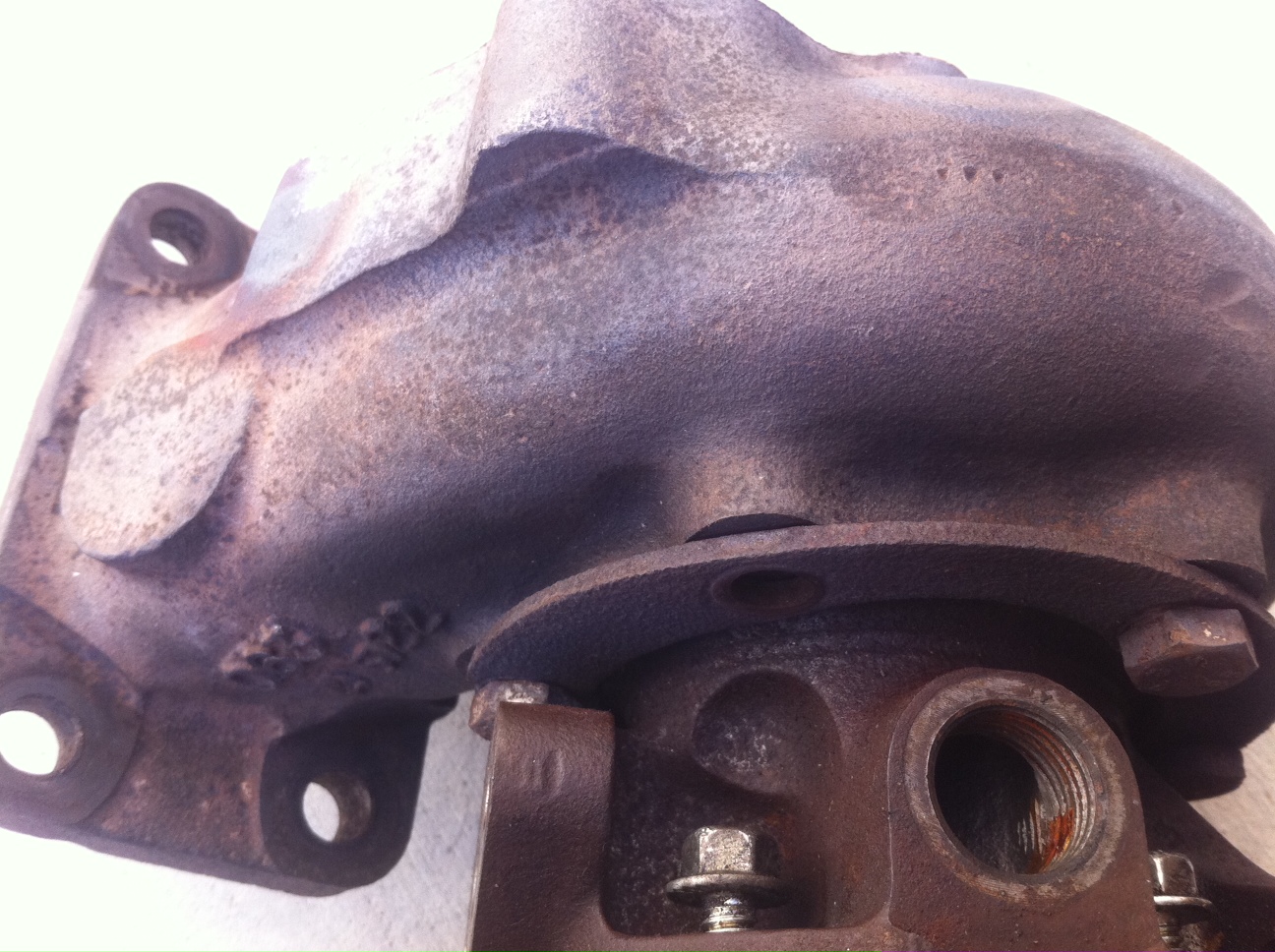
Well I went ahead and attempted to fix this broken stud issue on my own and was quite successful so I wanted to share what I did in case anyone else finds themselves facing this issue. It turned out to really not be that difficult at all, just took a little thought and patience to get it done right. I started by cutting off all the broken studs and flushing them with the surface of the housing. No pics of this step but you get the idea. I tried to just center punch in the middle of the broken and studs after they were ground down but was not too successful getting a "perfect center" so I thought about it for a while and made up this "guide" with a bunch of holes the size of the drill bit I'd need, I had some 3/4" thick steel laying around at work which worked great to help guide the bit in and keep everything centered. Here's the guide... I was able to visually center up the guide over the studs I needed to drill out and then clamp the guide down in several places to hold it in place VERY tightly. This ended up making easy work...though it took a while to reposition each time. I chocked up the whole turbo in a drill press vice and shimmed it here and there within the vice to keep it level (no pics, but I just clamped the compressor inlet into the vise and shimmed around the "body" of the compressor because I couldn't tighten the vice enough to keep it from wobbling around...once I put the shims in place it was rock steady for drilling.) So after leveling evertything up on the drill press I drilled out the holes I needed. I wasn't sure if I'd be able to chase out the existing threads with the appropriate tap so I went the next size up (from 5/16" to 3/8" fasteners) and drilled out the right size hole to be tapped. Tapping the metal didn't turn out bad at all...in fact I used a cheap Harbor Freight set I've had and not used in years and they worked just fine. I just had to be careful tapping...Once i was started I would go 1/2 rotation then back out 1/4 turn, lube with cutting oil, then repeat til I bottomed out or had enough threads. Here's the finished product after I took a file to it to flush everything up (the tapping process "pushed up" the metal around the edges of the holes. (I put some bolts and the tap in for effect...those aren't the bolts that'll stay.) Last thing I did was make sure everything lined up...so i had to enlarge the bolt holes on the Z31 downpipe since the bolts were now larger diameter. Everything lined up great so although I don't have the L28ET wastegate assembly to line up (it's still on the motor and it's been WAY too cold out lately), I know that all I'll need to do is enlarge the holes slighty and bolt it on. So that's what I was able to come up with...got to keep all my original stuff, and didn't have to spend a dime, just had to spend a bunch of time on it, but it was actually a fun project. I do have one more question now though...What fastener would be better for reassembling this, stainless or grade 8??? I figure stainless because of the heat it'll see, I just want a quality fastener so in case I ever have to take this apart again I may avoid having the bolts break again.
-
Thanks for the replies guys. Dan 5138, I wish it would be that easy, but I'm thinking those babies are STUCK. Rayaapp2, your explanation seems like the likely case based in what I observed while getting them out. It seems like there's only about 1/4"-3/8" of threads actually "in" the housing when it's all bolted together...I'll have to check in a bit how deep the entire hole is before bottoming out. What are your thoughts on drilling out the old bolts and just stepping up the smallest size (maybe from standard to metric even) OR just reaming out the threads once I get most of the bolt drilled out?? Something some common sense and patience can accomplish??. I don't want to drop too much more on this turbo...I'm only into it (t3/t04e) $250 right now. Also I have a machinist at work that would gladly perform the operation for me for a small fee (way less than a machine shop charging big $/hr. locally) but I really think I could tackle it myself. The biggest concern I have is tapping the cast...but research leads me to believe I just need to do it slowly (1/2 turn, then back out 1/4, and repeat) of course come Monday I'll chat with my shop machinist. THOUGHTS?????
-
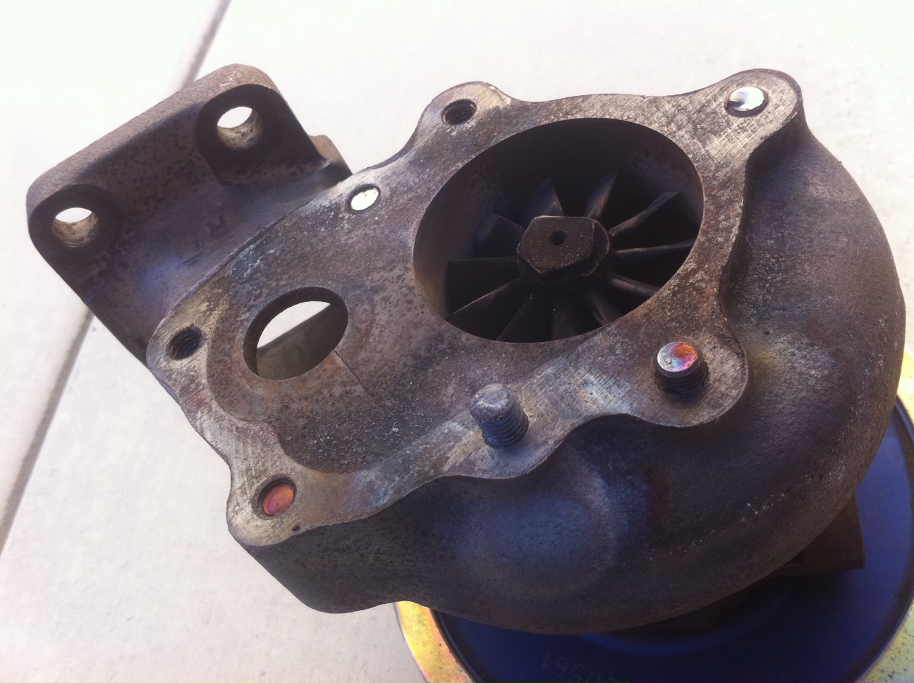
Hey guys...I posted this question along with some others in the Fabrication Forum and wanted to bring it to the Turbo Forum too. I was messing around with the bolts on the water cooled center section of this turbo that had orignally come off of a Z31 that I'd be adapting to put on my L28ET setup in my S30. The first one I tried backing out sheared off the bolt head with surprisingly little effort. I was very bummed about this because I was just experimenting with clocking compressor housing (super easy of course) and after having read a thread here about adapting the Z31 turbo for use on the L28ET thought it would be worthwhile to see if I could also "clock" the center section in relation to the exhaust turbine housing (a member had mentioned the oil input would not face "straight up" with the configuration of the center section of the Z31 turbo). Anyways enough back story...now I have 1 of the 6 bolts not holding anything down because it's got no head. Am I going to kick myself in the near or distant future of this turbo's life due to having oil and/or coolant leaking from this area because I'm missing 1 of 6 bolts with this thing getting quite hot and cold, and expanding and contracting?? What are you guys thoughts...can I leave it as is, or should I bite the bullet and try to get the remaining bolts out in some way and repair with a tap and/or Helicoil, all the while hoping the other bolts dont do the same??? By the way I had BAD luck getting the stock downpipe studs and bolts out using a rosebud to heat the housing (over half ended up backing partway out only to still shear off), and I have a major fear the rest of the center section bolts will do the same. Thanks for your time guys.

-
Hey guys I got myself into a bit of a mess. I bought a used turbo that had originally been on a Z31 and started working on getting the downpipe/wastegate assembly off the turbine housing so I could get it setup for swapping over to my L28ET setup. Bolts were all seized up so I got out the rosebud torch to put some heat to them and successfully got less than half of them out, with the others backing out partway and eventually shearing off. So I'm wondering what would be the ideal way to go about solving this dilemma of getting these out or tapped. I'm under the impression that I can drill these out carefully in a drill press in a couple stages and as long as I am well centered can hopfully just tap out the rest of the bolt and essentially clean out the existing threads. I'm also wondering if getting a kit to install Helicoils would be better than banking on being able to tap out the existing threads. I really don't want to have to pay a shop to do this since I have access to a nice large drill press and taps to ream out these holes, a fair amount of confidence in my light fabrication skills, and plenty of time. any thoughts would be much appreciated. Also while I'm at it...Being just plain dumb at the moment I was trying to see if the bolts on the center section were any less seized up and with (what I thought to be) not much torque and effort I accidntally broke the head off one of the 6 center section bolts. Will I end up kicking myself for taking the easy way out and just leaving it this way and have oil or coolant leakage because of this?? I'm worried because of the bad experience I had with the downpipe studs and bolts that it will just end up happening here too and have that much more work drilling out and tapping or Helicoil-ing. Thanks guys.
-
Here's a photo of that Sport 400 you were asking about Mark. Ben at JWT said a customer had brought this in when he upgraded to one of their newer turbos.
-
OOPS>
-
Thanks for the info...I figured metal sealing to metal would be the case due to the super high heat. One other question. The oil intake port on the turbo that Pyro had mentioned should be facing straight up...is this a necessary step?? Is this just being suggested so that the routing for the oil lines stays the same or is it a necessity to have it facing straight up for proper lubrication?? I think you'd said you used a longer hose for the oil outlet from the turbo to the oil pan, right? Thanks again, this thread has been very useful for a newbie like me.
-
Hey Hawkeye you're still here. So is clocking the compressor just as easy as loosening the bolts and rotating it, no seals, gaskets, any anything to be extra careful with to avoid tearing anything up??
-
Don't know if you'll get a response...looks like Utah Hawkeye (OP) just posted this how-to up then stopped posting.
-
Specs are: "The T3 turbine housing is a .63 A/R ratio and the T04E compressor housing is a .50 A/R ratio." -JWT I have to wait till I'm home tonight to post up pics.
-
I'm going to be doing this pretty soon since I bought a Sport 400 (From JWT) that was previously on a '84 300zx. Can anyone with turbo knowledge tell me if there are any gaskets or seals that need to be replaced or taken special care of when clocking the compressor or exhaust turbine as Pyro had mentioned. This will obviously be my first time doing this. I have average mechanical skills (not a dummy). Is this one of those things I should leave for someone skilled though so I don't screw up my nice turbo in the process??
-
Don't take offense man...rules are rules. I haven't personally done this but the intake you're referring to will be fine and more aesthetically pleasing since that's what you're after. If you want a "little" more power you just need to get a boost gauge and turn the boost up a couple PSI. 300HP is by no means "monstrous" for the L28ET either. Forged pistons seem like a big waste of money for the moderate bump in power you want. Why keep everything else bone stock and waste money on high end pistons??
-
I got you some measurements...I triple checked these on both passenger and driver door and had only about + or - 1/32" variation...so pretty tight between the two panels. Door panel to front of latch hole...13 3/16" Door panel to bottom of latch hole... 1 5/8" Door panel to FRONT of regulator...10 5/16" Door panel to BOTTOM of regulator...9 5/16" Door latch hole is 3 3/8" wide by 2 1/8" tall Window regulator is approx. 7/16" diameter Note that the hole in the panel for the regulator is about twice that diameter (3/4" hole should leave enough wiggle room for variances in panel placement. Also note the regulator measurements are to the FRONT and BOTTOM of the knob...to find the location to center the hole you'll drill please add half of the 7/16" diameter to these measurements. (Should be 10 17/32" from front of panel and 9 17/32" from bottom of panel for the CENTER of the regulator knob. And about a 3/4" hole.) I hope this is precise enough. If you need any more measurements I can take them.
-
I got you some measurements...I triple checked these on both passenger and driver door and had only about + or - 1/32" variation...so pretty tight between the two panels. Door panel to front of latch hole...13 3/16" Door