Sirpent
-
Posts
229 -
Joined
-
Last visited
-
Days Won
1
Content Type
Profiles
Forums
Blogs
Events
Gallery
Downloads
Store
Everything posted by Sirpent
-
Sirpents 260Z / C32 AMG Powered RS30 - Australia
Sirpent replied to Sirpent's topic in S30 Series - 240z, 260z, 280z
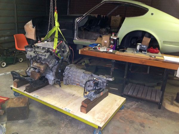
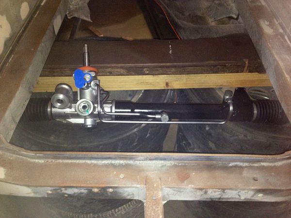
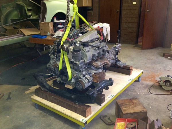
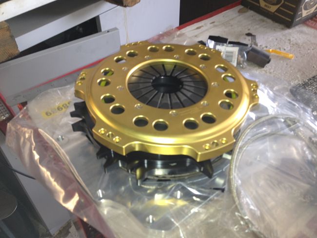
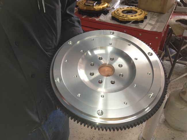
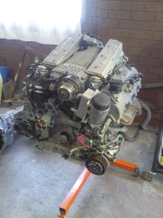
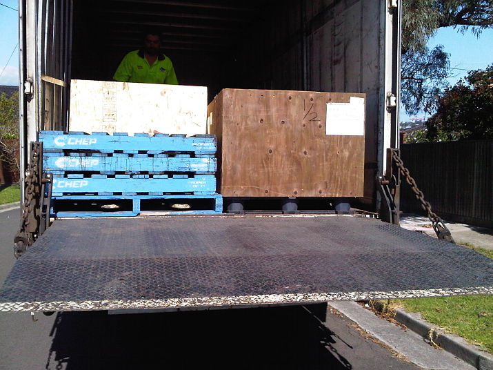
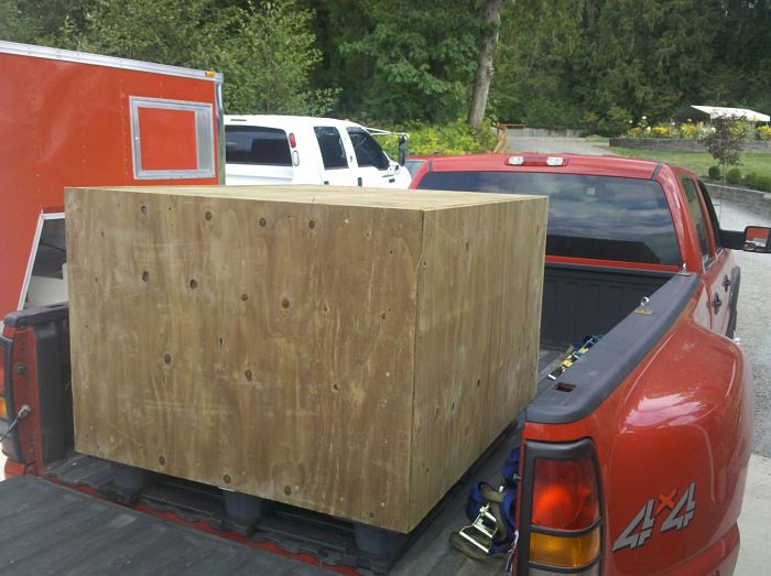
Well it’s been a long time between drinks, but yes I am still around and the project isn’t dead, was just put on hold while I embedded myself into my new job which meant a load of travel and little time for anything else. Anyhow, there has been movement in the past few weeks as on the 17th and 18th 0f this month a bunch of guys off the Auszcar forum will be coming around for the chassis building day bringing to life the chassis design I did some time ago now. In preparation, I’ve got on with making some final structural and component decisions, the major one being getting the adaptor design I conceived produced and mounted, the guys I chose to do this are a mob known as Alloy Racing Components here in Melbourne Australia http://www.alloyrace.com/index.php They also produce and construct a lot of street and strip gear, having made a drivetrain trolley, I mounted the engine and T56 and drove it 40 miles across town dropped it off and spent some time with John the owner, 3 pics below show the engine and trans coming off the utility, and the other 2 examples of the twin plate clutch and custom alloy flywheel similar to what will be going into mine, I will post pics of the work they do as they forward them onto me. Along with the engine and trans, I needed to make a decision on the rack and pinion set up into the car as I won’t be using the original S30 cross member and I now will have some room to play with, a lot of guys use Subaru or BMW racks, but my hunting came across something more local. Below is a pic of a rack out of the Australian FG series Ford Falcon G6ET, this is a pretty refined piece of kit which boasts variable-ratio functionality, for optimum low-speed steering sensitivity and a more relaxed tiller at higher speeds with 2.6 turns lock to lock, this mirrors the S30 to the “T†The setup is produced by Australian company Bishop Steering Technology who are suppliers of similar set ups to Porsche and BMW, the only issue of any note is that the LCA pivot points on the S30 are 610mm apart, while this set up is 620mm, that’s about 3/8 of an inch which we don’t believe will cause any great issues as the mounting of the rack to counter any bump steer issues shouldn’t be too difficult. I picked up a steel K frame out of a Benz S400, not easy to find as most of the modern Benz’s use alloy set up’s, this will be cannibalised and used as a fixed cross member welded into the chassis as it won’t be carrying the lower control arms or any other components on it. The fuel tank has to go as where it currently sits is where I intend to run the mufflers on the car, so I came across an LPG donut tank, paid $5.50 for it on EBAY, retail on a new one is around $400.00 these things are pretty heavy however have a 65 litre wet capacity which is just over 17 gallons, the tank as seen below will sit in the spare wheel well, we will be cutting and access point in the upper face and fabricate a bolt on access panel which will carry an inductive fuel sender unit feed and return pipes along with internal fuel pump and sump, a filler neck inlet will be added to the tank also. Another neat piece of kit was the NEW Saleen Mustang T56 cross member I scored out of the US for $50.00, this will give the mounting of the box a nice finish with proven functionality. Well that’s about it, I will start posting more as things move towards the 17th and the boys at ARC send across pics of the production process. Cheers John
-
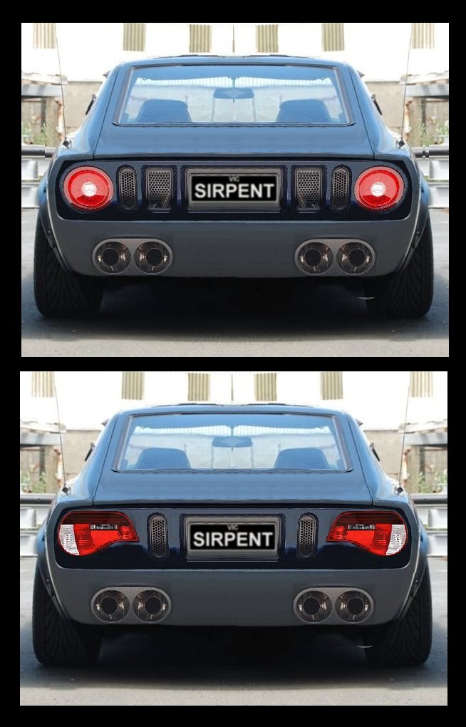
Hi guys, Someone mentioned Z4 tail lamps on here some posts back and wanted to know if they ever did it, Im toying around with a few idea's myself and the Z4's are one, here are my hack attempts at creating a visual using Ford GT and Z4 tamps. Cheers John
-
Sirpents 260Z / C32 AMG Powered RS30 - Australia
Sirpent replied to Sirpent's topic in S30 Series - 240z, 260z, 280z
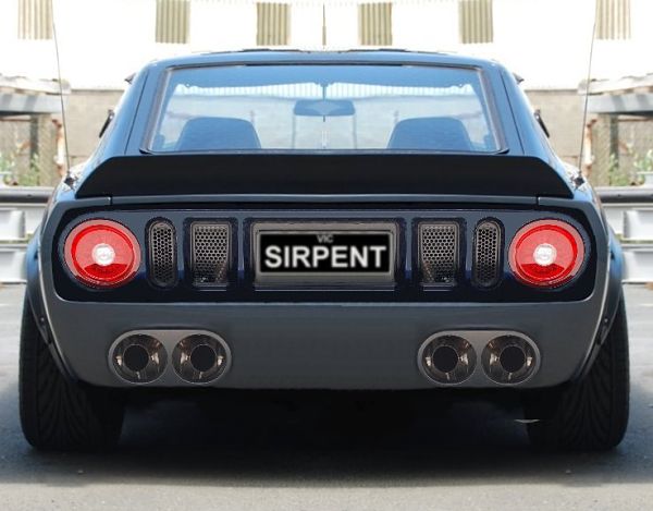
To each his own I guess, as I mentioned this started off as a forum styling exercise first and foremost, personally I ike the Z4 lights, at first not so much but the more I look at them the more they appeal to me. The round lights are off a Ford GT, now can you imagine how hard or expensive it would be to find a set? -
Sirpents 260Z / C32 AMG Powered RS30 - Australia
Sirpent replied to Sirpent's topic in S30 Series - 240z, 260z, 280z
Thanks John However this al came out of a thread that was started on our forum in Oz, and I started to play around with some idea's The tear drop lenses are of a BMW Z4, they are flat/er mount so in theory can be done, I just think they give the rear a very contemporary look. I did one last adjustment to these, I raised the lamp positions, and took away the Bob Tail spoiler and I think it makes a difference again making the rear look much sleeker.
-
Sirpents 260Z / C32 AMG Powered RS30 - Australia
Sirpent replied to Sirpent's topic in S30 Series - 240z, 260z, 280z
Happy New Year to you all from Down Here LOL Hope to post some updates in the coming weeks, been a bit slow, but back on my Aussie home forum we have been discussing tail lamp mods and came up with 2 posibilities, thought I would share. Cheers John
-
Sirpents 260Z / C32 AMG Powered RS30 - Australia
Sirpent replied to Sirpent's topic in S30 Series - 240z, 260z, 280z
Thanks Buddy See you are from WA (Washington State?) Imagine, that motor was sitting in Seatle WA just a few months ago. -
Sirpents 260Z / C32 AMG Powered RS30 - Australia
Sirpent replied to Sirpent's topic in S30 Series - 240z, 260z, 280z
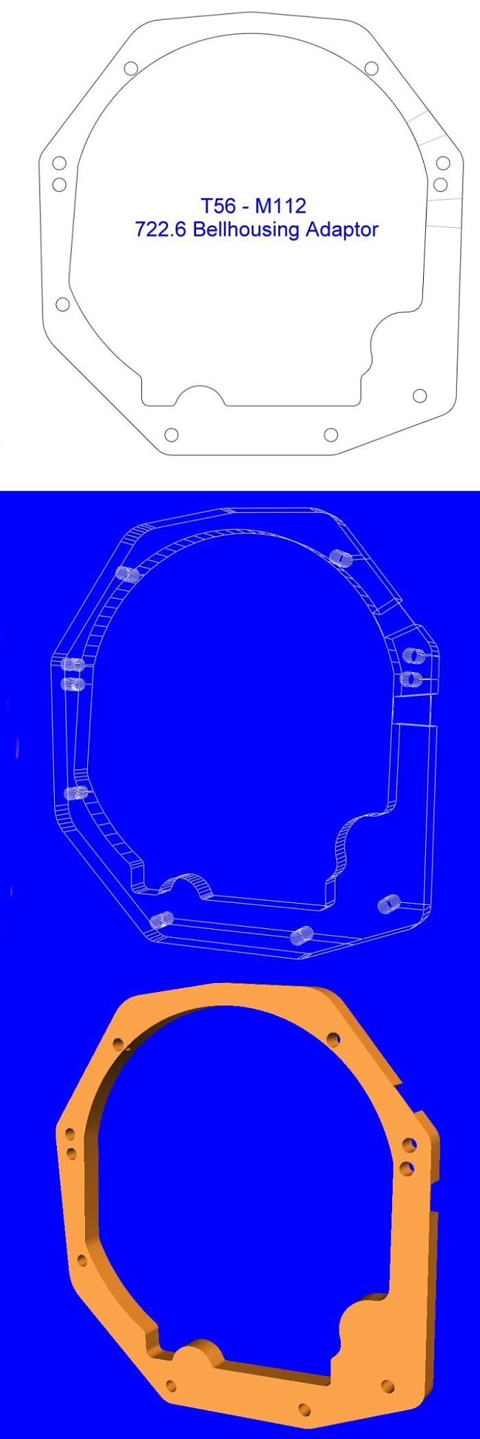
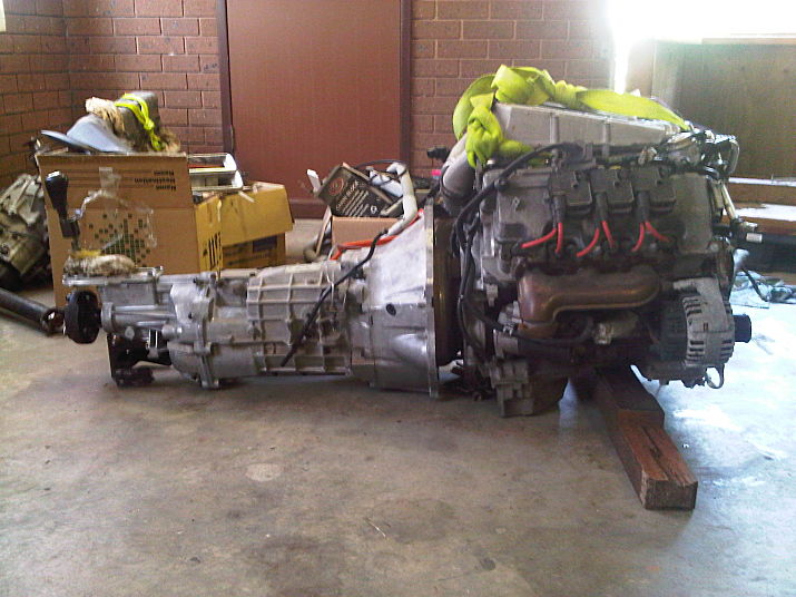
UPDATE Started a new management role a month ago so have spent the last 3 weeks traveling to all the major cities across Australia meeting my new staff, in between I have been home for the weekends but havnt had much of a chance to do much. Have however been able to get into a new (Used)work drive car, thought what the heck may as well have something I can refer back to with the project so have planted my behind into a CLK320 (The non Supercharged version of the C32) I also managed to do the CAD work for the T56 adaptor, so for those of you who ever wondered how I would get the T56 six speed behind the M112 well here is the tough part, the adaptor that will be needed between the 722.6 trans bellhousing and the T56. Took some doing but the initial CAD file is ready, I will have a test alloy plate cut to check final dimensions but at this stage all looks good. There are other features to this adaptor that I have hidden as they are my IP, however once the final product is produced and proven I will be making it available upon request. Also lined up the box to the motor just for a rough idea of center shifter position to the rear of the motor and where it would sit in the bay, the supercharger intake at the rear of the heads should sit about 8" (20cm's) from the firewall. Cheers John
-
Sirpents 260Z / C32 AMG Powered RS30 - Australia
Sirpent replied to Sirpent's topic in S30 Series - 240z, 260z, 280z
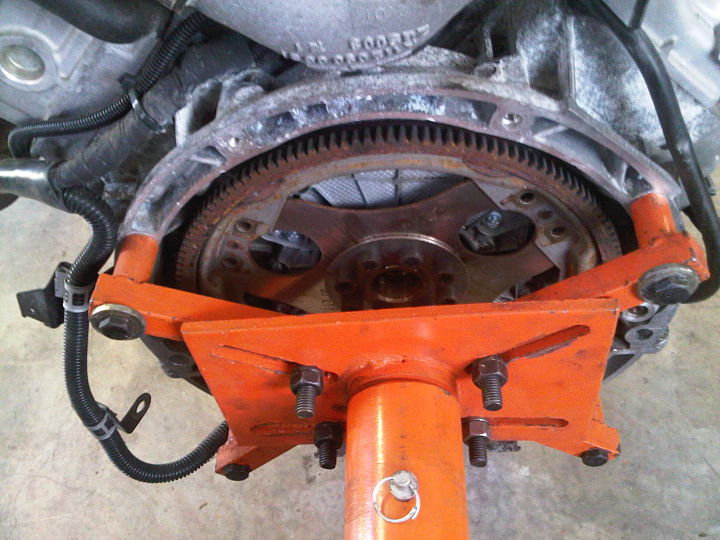
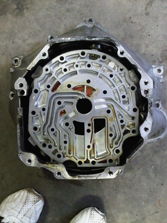
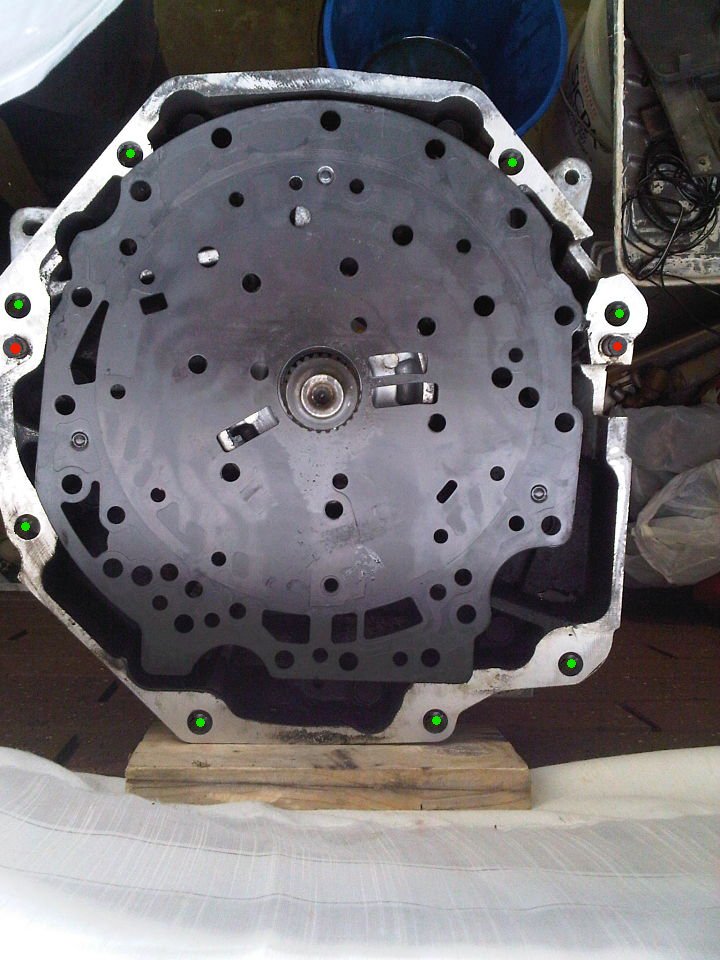
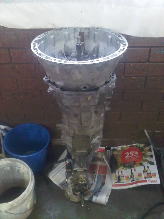
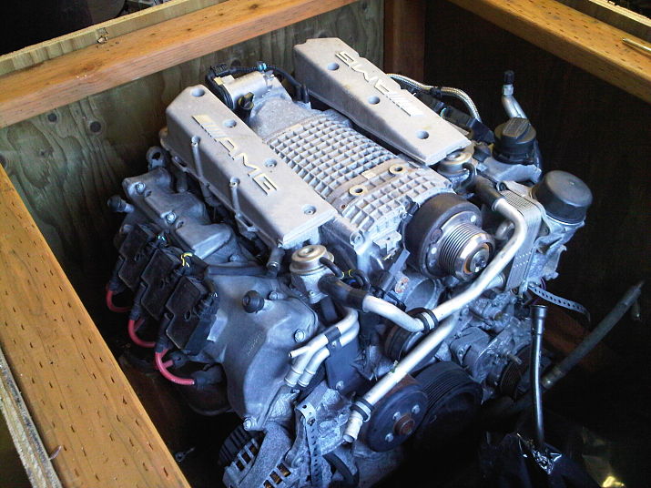
Minor Update OK, finally got around to doing some house keeping around the car and also started evaluating the engine box configuration, I must say that I was a bit worried but was pleasantly surprised once I got stuck into it all. Have attached some pics below. Engine : Have decided I am going to have the motor totally dry ice blasted, having inspected all the seals I couldn't find a single leak of any sort, not even tell tell staining of the alloy left even after a decent steam cleaning, so all good in this department, however the alloy is starting to whiten off with what I think may be salt rather than moisture oxidisation, so I partially stripped away the coil packs some of the tensioner pulleys harmonic balance etc so as to give the process better penetration. I also dropped out each of the "12" plugs, to have a look at the state of the electrodes, all good, no oil deposits, nice and dry, black carbonised in color. After doing some research I came across this link and then tracked down a guy in metro Melbourne who can come and do it for me, a hell of a lot easier than trying to get into every last nook and cranny mechanically, I will do a vid of the process when its being done for those that may find it of interest. Transmission : OK this was the fun part, I stripped off the T56 bellhousing, the Benz bell Housing, The torque converter from the engine, and mounted the motor onto an engine stand. After the strip down of the 2 trannies, I took the metal gasket which lived between the Benz Box and bell housing and lined it up to the front face of the now bare T56 box (Minus its bell housing) luckily the input shaft main bearing in the box is almost exactly the same as the input shaft hole on the metal Benz gasket, so I think I was able to align the plate to the box within a fraction of a millimeter. The reason for doing this is because I will be using the Benz housing and needed to see how the outer parameter of the Benz housing would sit in alignment with the T56, good news is that the T56 housing bell mount holes are all outside of the Benz parameter, this means that once I have a plate manufactured which will be welded to the Benz bell, there wont be any issues bolting it up to the T56 and using all the original mount points. The rear of the Benz housing will have the equivalent of the plates thickness machined off (probably 1/2 inch or 12.5mm) the plate will then replace that section and then the Benz bell will be welded onto this plate which will be in the shape of the T56 face, the depth of the T56 bell is 140mm while the Benz is 145mm so the new hybrid bell will be 140mm as was the original T56 bell housing. The green dots in one of the pics represent the T56 Bolt points, while the red ones represent the alignment dowles. So overall a productive day of discovery and good luck. Cheers John
-
Sirpents 260Z / C32 AMG Powered RS30 - Australia
Sirpent replied to Sirpent's topic in S30 Series - 240z, 260z, 280z
Yes indeed, Well I have made a start, ripped into the box this morning and did some more measuring and mock up alignments and all looks good, should have plenty of clearance to the bonnet also. Between the towers, I will have 50mm (2 inch) clearance either side, the motor max's out at a width of 700mm and the towers are 800mm's apart The Bell housings will be a bit tricky but from what I have been able to work out, I will have to cut the rear of the T56 housing away then splice it onto the Benz housing and have it welded with re-enforcements inside and out. This will require a jig with a central shaft to align the 2 sections, I will bolt the sections to plates, one plate will have a central shaft welded to it exact center, the other plate on the other section will also be bolted and will have a centrally drilled hole, this way I can align the centers of each and vary the distance between so as to square it all up. The T56 bell is to large at the face and part of it already breaches the rear feed tubes, second the Benz uses a partially internal starter and you just wouldn't be able to mod this nor adapt something for the T56 bell, so the only way forward is to use the Benz bell housing. Whats good here is that the Benz bell tapers inwards to the box interface and the T56 is wider and has bolts holding it to the box running backwards into the bell from the box side. Because of this cutting the T56 bell rear will create an over sized plate and also allow for comfortable welding and then the addition of re-enforcement gussets. If there was another way I would do it but both bells will have to be partially sacrificed. I have to get all this done first before I can even contemplate the chassis as I need the motor and box hooked up to get all the alignments and mounts correct. Some preliminary pics taken this morning while you all slept. Cheers John
-
Sirpents 260Z / C32 AMG Powered RS30 - Australia
Sirpent replied to Sirpent's topic in S30 Series - 240z, 260z, 280z
GAME ON ! Engine arrived today so time to roll up the sleeves.
-
Sirpents 260Z / C32 AMG Powered RS30 - Australia
Sirpent replied to Sirpent's topic in S30 Series - 240z, 260z, 280z
Thanks Buddy Just got back from a 8 day ski holiday in Queenstown New Zealand, engine hit the Melbourne docks this morning before I flew back in so will hopefully have some up close and personal picks in the coming days, planning a BBQ for some of the local "Z brain trust boys" in the coming weeks to discuss a chassis building weekend, my son is going to set up a time lapse video of the build so watch out for some interesting footage to come. Cheers John -
Sirpents 260Z / C32 AMG Powered RS30 - Australia
Sirpent replied to Sirpent's topic in S30 Series - 240z, 260z, 280z
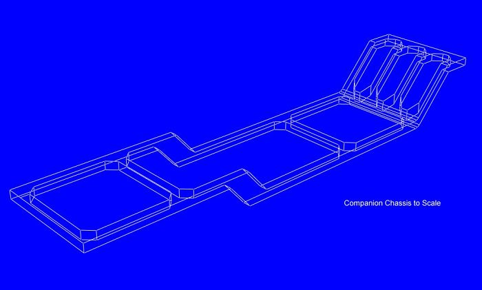
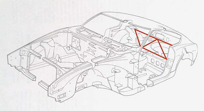
Well seems not much action here, but for those that are reading it some updates In preperation for the engines arrival and so as to waste the minimal amount of time when it gets here, I have pre-empted some of the fabrication and modification work, the following is an update of whats planned. 1st Motor lands in Melbourne after its trans Pacific journey from WA State on October the 1st, so Im hanging to get my hands on it once it passes customs and quarantine services. Had a hickup as the US shipping company wouldnt allow it out unless the plastic pallet I had was boxed up, this even though Australian Customs are OK with a secured clean and wrapped engine on a pallet, so through my agent here in Australia, Tony Garmey from Horizon Racing in Seattle picked up the pallet and goods, took it back to his workshop and repackaged it in a closed treated pine enclosure over the top of the pallet and delivered it back to the shipping agent. 2nd, I came up with an idea for a chassis design which would bolt in to the car rather than welding re-enforcement plating throughout the car, it got the thumbs up as far as meeting certification requirements and meet some of my objectives #1 Create a very rigid structure capable of dealing with the torque that's expected. #2 Build it in a way that would allow for almost the entire structure to be bolted in allowing for ease of removal. #3 Attempt to use the structure as the platform from where the engine, trans and diff mounted too, this would allow for the mounting and alignment of these components with the superstructure outside of the shell. So after creating a scaled drawing of the S30 from dimensional plans I had at hand, I came up with the attachments. The legend shows 3 color codes, the white areas are the OEM rails, Green the bolt in superstructure I have named a companion chassis, and the yellow weld in outriggers which will be welded into the floor and existing rails. The front cross member for the engine will become a solid welded feature into the new companion chassis allowing me to specific weld the crossmember for the mounts to the position of the engine. There is also a crossmember which will become a welded in feature also for the trans mounts and dual members at the rear which will cater for the diff allowing hang down mounts to suit the diff position, this should allow me to dispense with the rear diff cap mount period. The new chassis will bolt at the original engine cross member mount points, dual bolts will secure the chassis at each outrigger, and at the rear the chassis will bolt in at the moustache bar member, all bolt areas will utilise crush tubes where required. I know this may seem like overkill, however all up weight should come in at approximately 90Kg, considering that the new engine will be some 60kg (138 lbs) less than the L6 it doesn't phase me, in addition I have also decided to tie in the rear inner cabin suspension towers into the build with a removable tower floor brace (see attached) which will bolt through the rear floor to the companion chassis. By doing it this way, I can almost return the car to its OEM state if I ever decided to (Most unlikely) but more so I will be able to do all the final mounting and alignment of the engine, gearbox, tailshaft and differential with the chassis sitting outside of the car which is a God send. 3rd, I have decided I will dispense with the OEM fuel tank and run a dual system down the length of the car, mufflers will be mounted beneath the spare wheel well, I dont want to go cutting out the rear spare wheel well, In Australia its not compulsary to carry a spare, so the plan now is to have an alloy tank fabricated to sit inside where the spare used to sit. The tank will sit in the well and an aluminium circular plate would then have to be bolted over it therefore forming a firewall, the main neck and associated fuel lines would still come down through the 1/4 panel floor area and then sweep into the tank via a small access cut in the wheel well. After speaking to a fabricator in my area today and based on the dimensions and what I explained I wanted, he gave me an indicative price of $450.00 for a tank built of 3mm aluminium all TIG welded. The basic design (Rudimentary as I didn't have time to do a more detailed one) would be along the lines of the attachment, Internally it would incorporate 2 cross plates forming internal baffles, each baffle would have lower and upper galleries allowing for fuel to circulate into each chamber, the tank would have one pie shaped area sitting 30mm lower than the other 3 chambers into which the remaining chambers would cascade fuel into it creating a 2.4 litre pool or well. This pool should be deep enough for an internal pump pick up point, therefore an internal pump running 50+ psi would be required, this would not be included in the price of the tank as wouldn't the inductive (Non Float) sender unit. However the price would include the neck and all associated piping for return and vapours lines etc, fuel capacity will come in at 60 litres or just under 16 US Gallons. Well thats it all wrapped up in a nutshell. Cheers John
-
Sirpents 260Z / C32 AMG Powered RS30 - Australia
Sirpent replied to Sirpent's topic in S30 Series - 240z, 260z, 280z
Just a quick update for those still following this thread. Motor is now on its way and should be arriving soon, had problems with the shipping company but was all sorted out after a round of ping pong international calls and emails. As per previous posts, I have the new rear Diff / Suspension cradle all CAD'd up and thats ready to go as is the LSD Diff I picked up a few weeks ago. Today recieved my new T56 box and its nice seeing all the pieces of the puzle come together, the pics attached show itsitting next to the original "Z's" 5 speed just for a comparative, once the engine arrives and I can take some measurements of the bell housing I will make a decision on which bell housing I will use and therefore have the adaption plate made to suit. Cheers John
-
Sirpents 260Z / C32 AMG Powered RS30 - Australia
Sirpent replied to Sirpent's topic in S30 Series - 240z, 260z, 280z
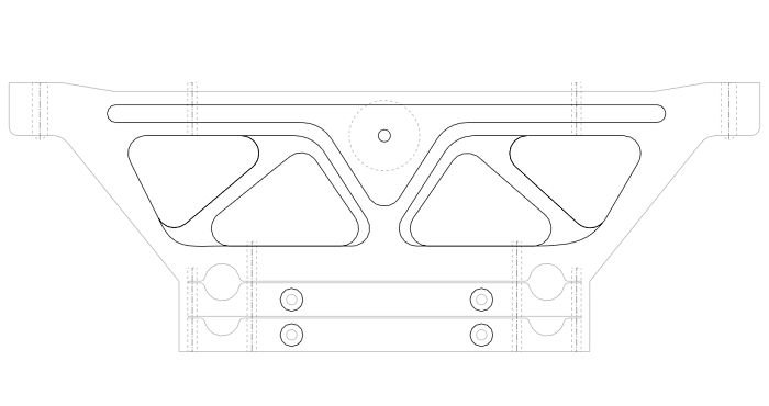
UPDATE Final cradle design done showing single cut process inclusive of nested lower suspension mounts. I have ordered a slab of 7075 - T651 Aluminium and the machinist is currently going over the CAD-dxf file I sent him. Think this is more in keeping with the original concept and a much cleaner design. Cheers John
-
Sirpents 260Z / C32 AMG Powered RS30 - Australia
Sirpent replied to Sirpent's topic in S30 Series - 240z, 260z, 280z
Update After tossing and turning over the carrier, I decided to crank up the old CAD program I had and have a crack at seeing what could be done in terms of creating a CNC'd Aluminium billet carrier. Attached is the preliminary wire frame image of what I have generated so far. Still a lot of fine tuning to do, as the diff rear mount point and also the lower cradle arms need to be mocked up now. Cheers John
-
Sirpents 260Z / C32 AMG Powered RS30 - Australia
Sirpent replied to Sirpent's topic in S30 Series - 240z, 260z, 280z
This is going to be a long update........... AT LAST It's official, motor should be here at Melbourne Docks on Friday 17th of August !!!!!!!!!!!!!!!!!! To celebrate I went out and purchased a diff today for the project along with a box I decided after much thought surfing and consolation,on installing an M86 LSD diff used in the the Australia XR6 Turbo Falcon and picked up a 20,00K diff, ratio is 3.46:1 So this weekend I spent much time designing a new cradle assy which will support the diff and firm up the rear suspension. As far as the box, I also secured a T56 box with chev bellhousing out of an Australian Commodore which ran a Gen3 V8 and got it for about half what everyone else was asking in the market place. So back to the rear cradle, what I am envisaging is utilising the moustache bar as a suspension mounting and fabricating a new beam from which I will then run a web structure down to the rearward control arm beams more or less creating a single structure carrier structure and ancillary control arm platform. From the rear control arm mount points forward I will run 2 horizontal beams to the forward facing control arm mount therefore creating a cradle off the original mounting points. The idea then is to use these beams as the bases for the side dampner mounts for the M86 diff. At the rear I will use the factory mount that bolts to the diff cover along with the factory dampner and have this bolted to the new rear carrier. The idea is that this moustache replacement will look similar to a C4 Corvette set up as per attached. If it works, then I can have the certification engineer go over it and advise what final modifications need to be made, a lot easier than trying to convey ideas and concepts. The new carrier no longer becomes the main insulator for the differential but rather a carrier for the suspension so will be solid mounted. Nevertheless it will still carry the diff aa it incorporates a rear mounted insulator held in place by a single bolt to the diff cover and dual bolts from the dampner to the mounting point which in this case will be the new carrier design, while the front has a dampner either side, so the entire diff floats so to say within the cradle. By using the new carrier in this way also, distribution of suspension forces are now spread across a wider area namely the rearward rails rather than the 2 drop brackets from the cross beam between them. I think it will work nicely as a package especially once I introduce Arizona rear control arms to the mix. The thumbnail sketch is just that and did a lot of measurements today of the original Z components so as to start a CAD file of the assy. At this stage an exhaust notch has to be added, also the rear carrier will have to include a centralised "Kick Out" on the upper beam to facilitate the rear diff mounting point. Some design changes will mean that the lower control arm pivot depressions will be built into the carrier and the cross beam will also have these so as to dispense with singular clamps. I did stuff up as I drew the front carrier upsaid down showing 2 separate clamps when in fact the body has the pivot depressions build into them meaning the front beam will be a single unit with a mirror image. All in all however clearances look very good and it may allow me to incorporate diagonal supports also running from the upper carrier down to the lower front beam, this triangulation should make it a more robust assy, but will see as I get closer with the CAD drawings. My only thoughts now are about the rear carrier mount points, the old moustache par pivots will work well but I'm also going to see if I can incorporate the remaining redundant hanger bolt points also, this will give me a 6 bolt point assy for the carrier. Any enlightenment from any members on the forum who may see or have experienced problems with a similar mod please feel free to post. Cheers John
-
Hey Bob Will be watching this now. Cheers John
-
Sirpents 260Z / C32 AMG Powered RS30 - Australia
Sirpent replied to Sirpent's topic in S30 Series - 240z, 260z, 280z
UPDATE: It just goes to show that no matter how much research you thought you have done, ITS NEVER ENOUGH ! In the past week I have learnt that the entire electronics system and hardware from a C32 sedan CANNOT be retro fitted into my car, that's the bad news. So after spending the better part of a day curled up in a fetal position sucking my thumb and thinking about my new position I tried to visualise exactly how the entire AGM package could work and came to the conclusion that dumping the auto trans, ECU and TCM and fitting a manual trans could allow me to move forward, what i have to do however is run something like a MoTeC M600 aftermarket management system instead. The reason for this is simple, after making another call to the UK and speaking to a tech at ATP about getting my ECU decoded so as to eliminate the security features I learnt that this was only part of the puzzle, the C32's ECU and TCM actually use telemetry from an array of other inputs such as the ABS, traction control, launch control and even suspension telemetry etc, if one of these telemetry streams is inactive the ECU and TCM read it as being a fault and the entire electronics go into limp mode. As we all know, Datsun even with all their visionary idea's in the 1970's never equiped my 260Z with such features and retro fitting them all from a Benz would end up costing me the price of a C32 sedan. If I was to use a manual stick shift like a Getrag with the MoTeC management system basically what I will be dealing with is a lump of metal with pistons injectors etc etc etc that the MoTeC can be set up for. I put my theory to one of Australia's best tuners, a friend of mine called Peter McDonnell and we did some soul searching on the phone and over the net and so far it looks doable. So now it looks like I will end up with not only the first S30 powered by a C32 AMG motor, but also the first C32 manual period "FINGERS CROSSED" Im lucky as MoTeC are in my home city.I spoke to them on the phone about the M600 unit to run the motor, as far as we can tell having crawled all over the M112 it should be doable even down to the fly by wire accelerator as the Motec provides input for it. The other good point is that we should be able to map and tune some more hidden potential out of those charged cylinders as a result. This is a link to the MoTeC unit in question if there are any tech's reading this that want to check it out. http://www.motec.com.au/m600/m600overview/ Plus side, it should be fun being able to use the left foot for some cog swapping as oppossed to just resting on the foot rest,this is the box thats planned for the conversion known as a Getrag M90, it was used for years here in Australia behind production GM V8's and will be up to handling the torque of the M112 motor. This is a link to a local supplier showing the box in question http://www.holmart.com.au/online/prod438.htm This will mean the fabrication of a adaptor or modified bellhousing and using a flywheel from a standard C320 Benz non supercharged manual box, unfortunately these boxes just aint up to the task behind a supercharged version of the motor and hence Benz never produced a manual C32. Cheers John -
Sirpents 260Z / C32 AMG Powered RS30 - Australia
Sirpent replied to Sirpent's topic in S30 Series - 240z, 260z, 280z
2000 W210 Mercedes E Class sedan Bang. -
Sirpents 260Z / C32 AMG Powered RS30 - Australia
Sirpent replied to Sirpent's topic in S30 Series - 240z, 260z, 280z
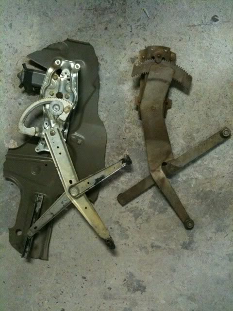
OK, getting close to the point of finishing this mod off, everything is now aligned nicely, gaps are great and apart from a few behind the scenes mounting points I need to weld in, all's good. So to keep the mind occupied, Im also turning my attention to the electric windows and looks like I have found a suitable donor system out of a local GM car (left hand reg in the photo next to the S30 on the right)to play around with, these units are very ceap brand new off the shelf here at around $70.00 a pop, and are plentyful, so nothing lost in trying. And finally, Ive also decided that the headlamps need some attention, so Im looking at sourcing these and giving them the chop (deleting the driving light) and weld treatment for transplant into the "Z" Will post as things develop. Cheers John
-
Sirpents 260Z / C32 AMG Powered RS30 - Australia
Sirpent replied to Sirpent's topic in S30 Series - 240z, 260z, 280z
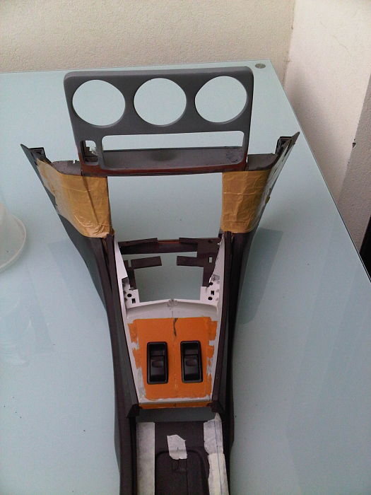
First trial fit of the 3 pieces together in the car, some tweaking to do but overall alignments are good Cheers John
-
Sirpents 260Z / C32 AMG Powered RS30 - Australia
Sirpent replied to Sirpent's topic in S30 Series - 240z, 260z, 280z
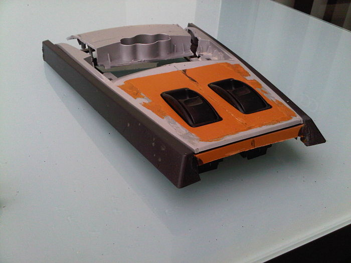
Centre Console Gear Shift Fascia now almost done, obviously an access point will have to be cut out for mounting of the gear shift bezel etc. That will the determine where the reinforcements will go on the underside, next is to set the surround of the fascia in black into the centre console and weld that into position. Cheers John
-
Carlos. Nothing like seeing it all come together as a builder restorer, and inspirational to others who get the chance to see it in a build thread like this. Stunning car and workmanship, concratulations. Cheers John
-
Sirpents 260Z / C32 AMG Powered RS30 - Australia
Sirpent replied to Sirpent's topic in S30 Series - 240z, 260z, 280z
Forgot to add how the switches came to be and what they are from, ES300 Lexus passanger items. Cheers John
-
Sirpents 260Z / C32 AMG Powered RS30 - Australia
Sirpent replied to Sirpent's topic in S30 Series - 240z, 260z, 280z
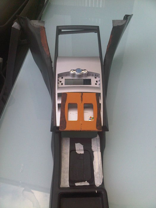
Started looking around at what I could use and modify to produce the centre console fascia......... The wonderful thing is that so many items today are mode from plastic and if you look carefully enough you re bound to come across something that has the intricate well fitting forms you need, in my case I needed something to fabricate the fascia from and also something that would act as the bed in which it sits, low and behold, I came across an old Compaq PC case I was going to turf and the front fascia gave me some idea's, the following are a selected few pics of what transpired. As soon as I get the gear shift bezel I will be able to lock up the front surface and fabricate a support panel to mold into the new fascia. Cheers John