Sirpent
-
Posts
229 -
Joined
-
Last visited
-
Days Won
1
Content Type
Profiles
Forums
Blogs
Events
Gallery
Downloads
Store
Everything posted by Sirpent
-
Sirpents 260Z / C32 AMG Powered RS30 - Australia
Sirpent replied to Sirpent's topic in S30 Series - 240z, 260z, 280z
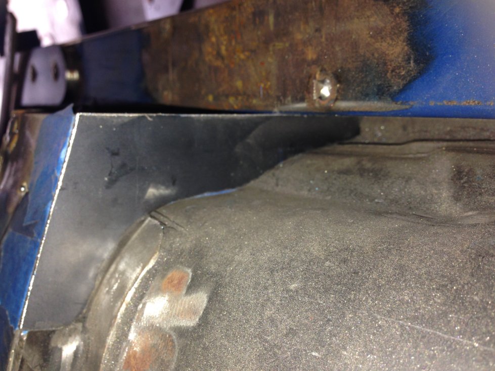
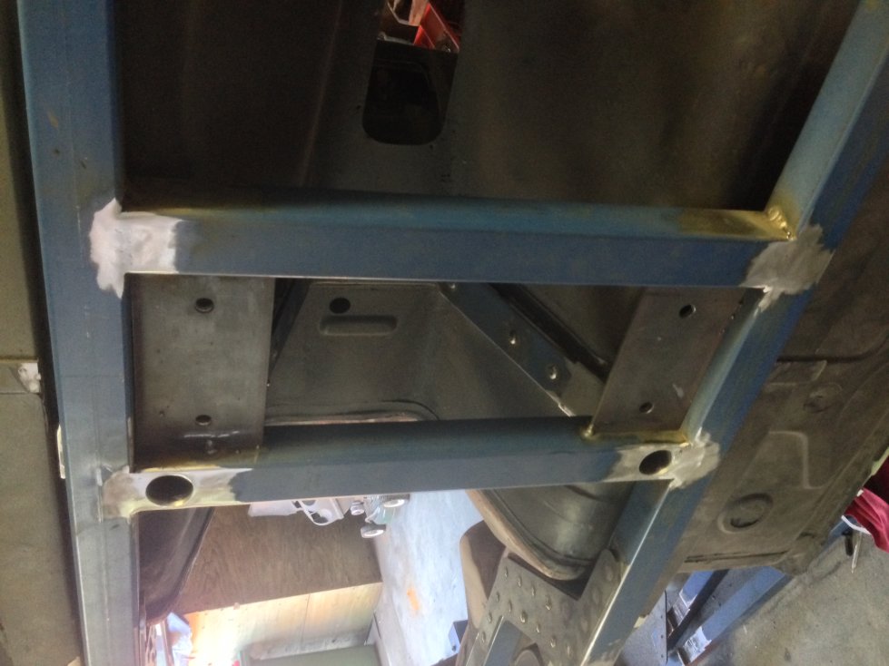
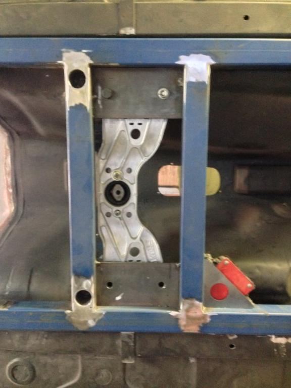
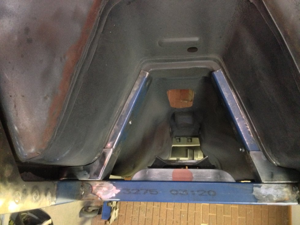
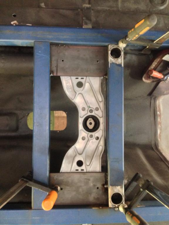
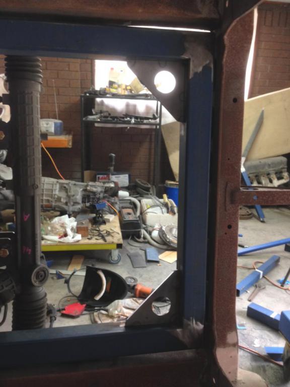
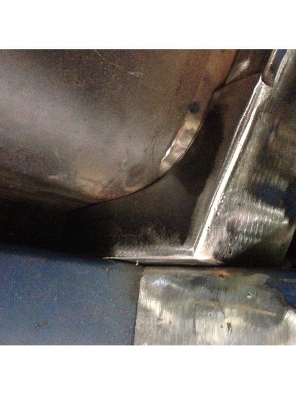
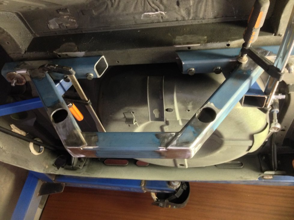
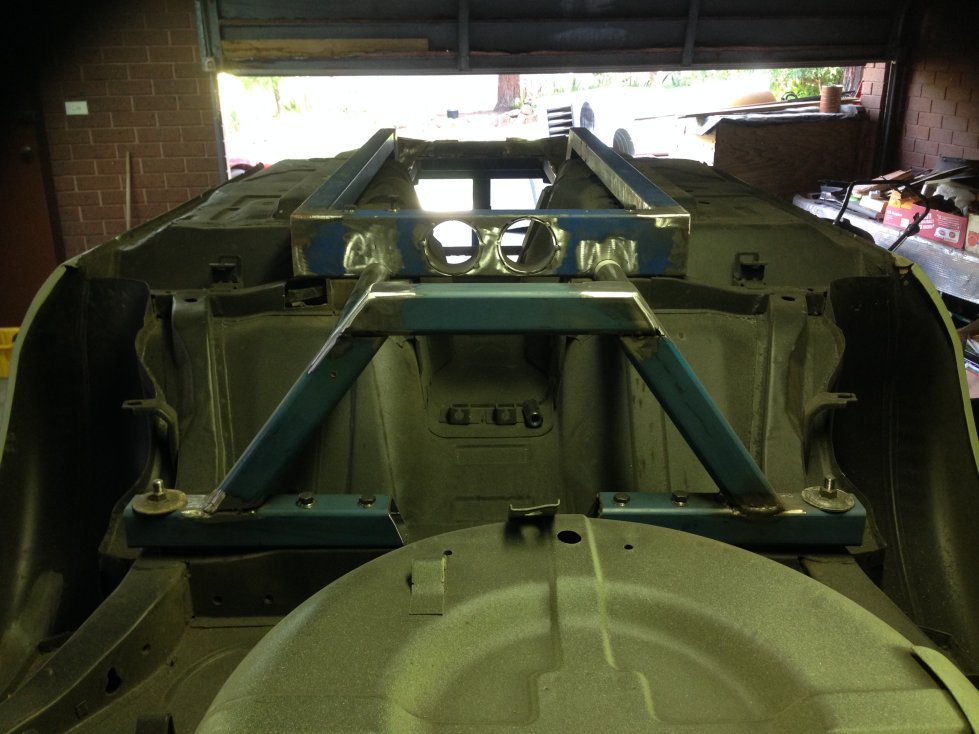
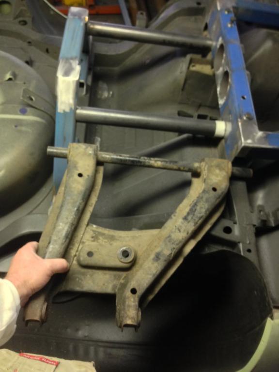
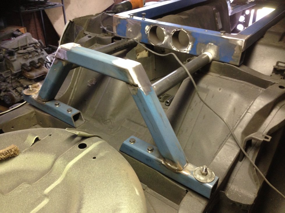
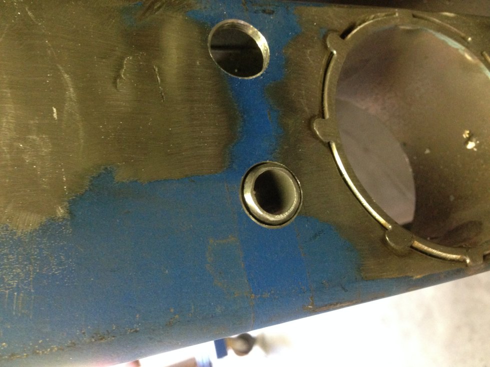
So had some time this afternoon and fabricated what I call "Hockey Sticks: which is what the tunnel reinforcement plates look like (See below) Each needed an individually shaped infill gusset made so I took a leaf out of "Project Binky" and did some CAD (Cardboard Aided Design) design and made each piece individually before fully welding the internal side and outside faces to form the reinforcements. Then I drilled and aligned the transmission mount members and welded in encapsulated nuts before finally temporarily plug welding them in place bolted up. Even seem to be getting my welding groove back at last LOL Each of those reinforcements and gussets will be permanently welded to the old transmission reinforcement and the floor contours. I’m on the home stretch now and hopefully after welding in the gussets, 2 remaining fish plates and forming the mounts for the new front suspension tension rods I will be able to weld up a trolley frame to bolt it to this weekend which will allow me to work on additional welding on the chassis and start the rear diff mounting in tangent with the engine mounts and mounting the engine etc. outside the car. Cheers John
-
Sirpents 260Z / C32 AMG Powered RS30 - Australia
Sirpent replied to Sirpent's topic in S30 Series - 240z, 260z, 280z
That's a big compliment ! Thanks Buddy -
Sirpents 260Z / C32 AMG Powered RS30 - Australia
Sirpent replied to Sirpent's topic in S30 Series - 240z, 260z, 280z
Good question Remembering that for the better part of 3 years I didnt do any work on this project due to work and family issues, I'm now in the home stretch so to say, putting an estimate on it, and dont hold me to it, at least another 18 months. The sequence from here is #1 Finish the chassis fabrication #2 Have the custom rear LCA's fabricated to suit the final position of the hanger brackets #3 Remove the chassis and mount it to a fabricated trolley set up #4 Have the final diff mount plate cut and fabricate the bushes and mount plates #5 Align the diff to the gearbox angles and have a tail shaft fabricated #6 Drop the body onto the chassis to see if my calculations and measurements are correct and trim the floor pan if needed (at the moment I dont think I will have to) #7 Fabricate the engine mounts #8 Sort out the steeing rod and mounts #9 Have the engineer come to check it all over and certify all is in order so I can have it road registered later down the track #10 Fabricate the ancillaries such as brake / fuel line mount brackets #11 Have the twin exhaust system fabricated and test fitted along with all hangers #12 Have the donutt LPG tank modified and fitted #13 Order and fit the Mustang radiator and mounts #14 have the engine started (This will be done by a buddy mechanic of mine along with the wiring, MoTec 600 management system etc) From there on in its all bolt on's body work and interior and lots of cash for all the bling and aftermarket pieces As you know due to your build, the fabrication work is the toughest and most critical. Cheers John -
Very Impressive
-
Seriously ???????????????? I feel sick when I look at mine and then see yours LMAO And you said I might have given you an idea, well hell Im pinching one back from yours after looking at the "MEAGER" amount of work you did. Love your work
-
Sirpents 260Z / C32 AMG Powered RS30 - Australia
Sirpent replied to Sirpent's topic in S30 Series - 240z, 260z, 280z
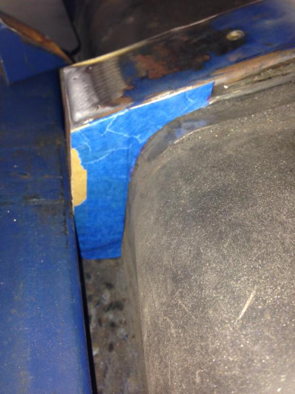
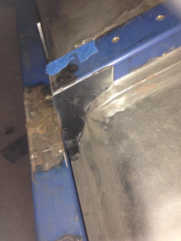
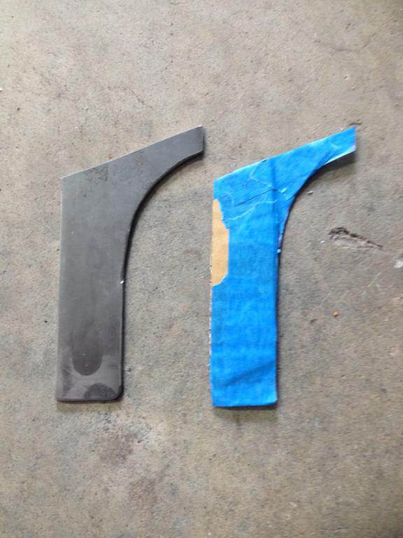
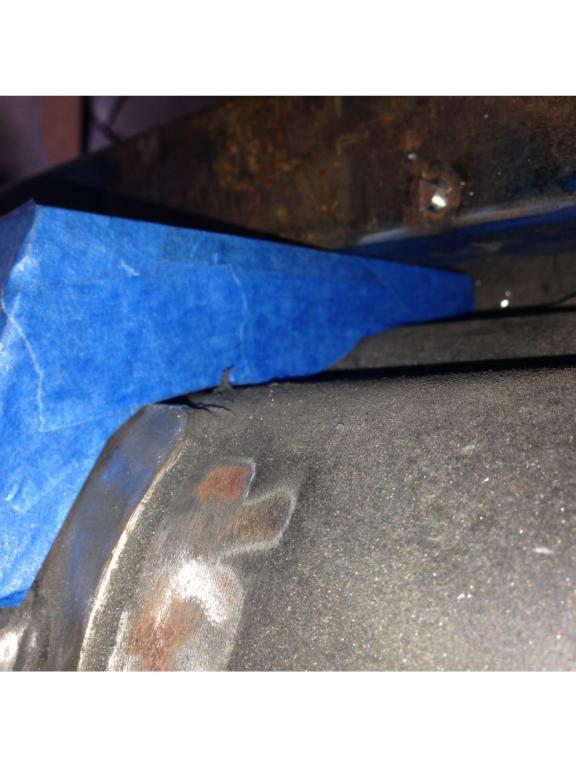
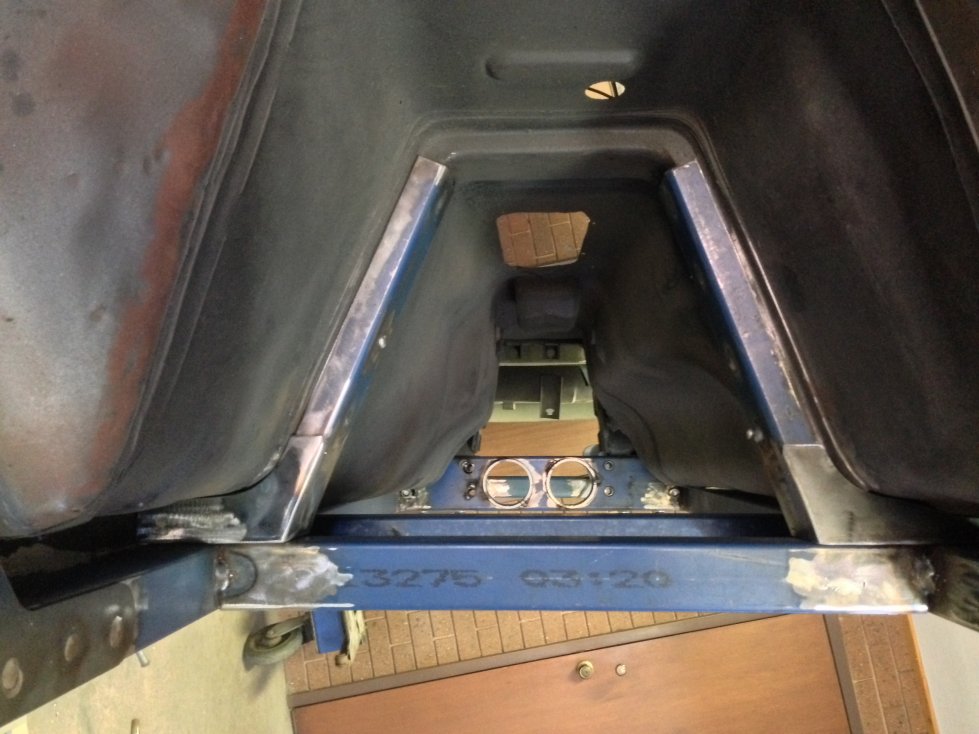
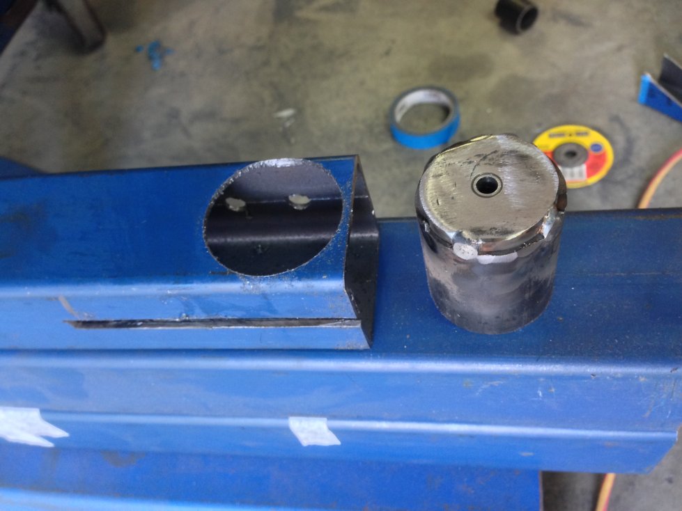
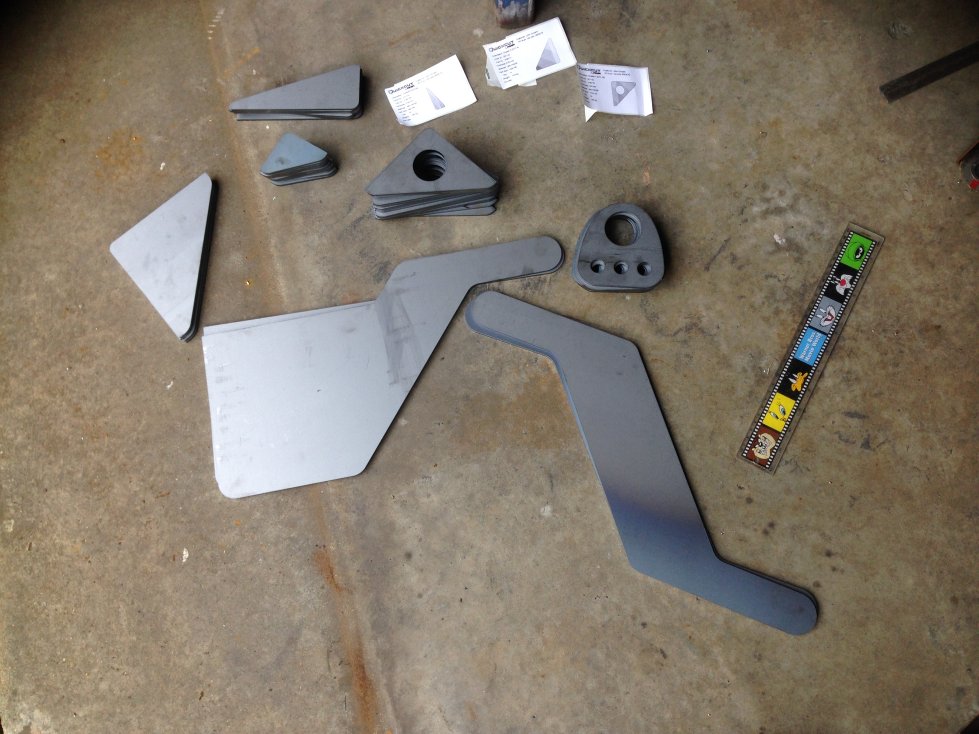
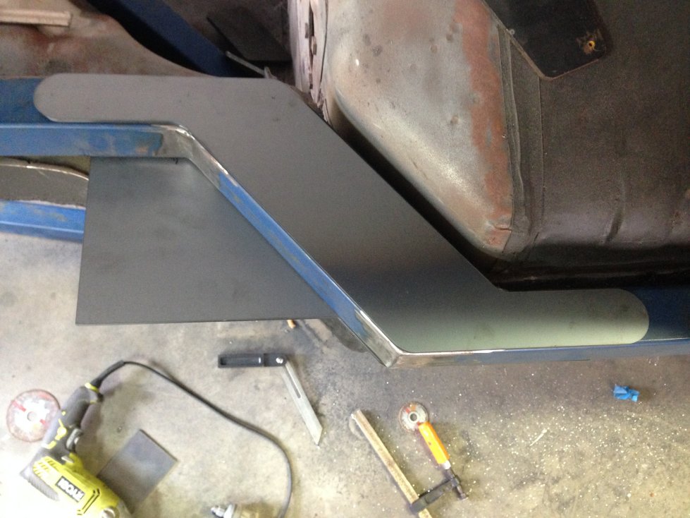
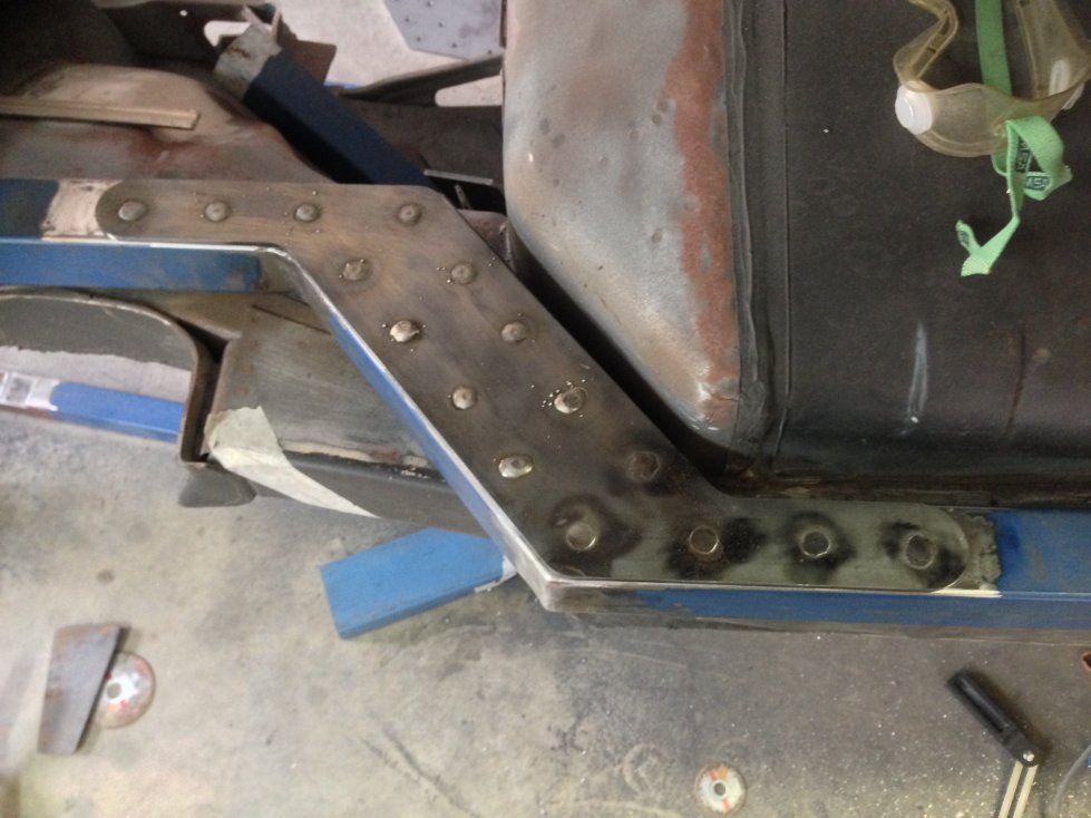
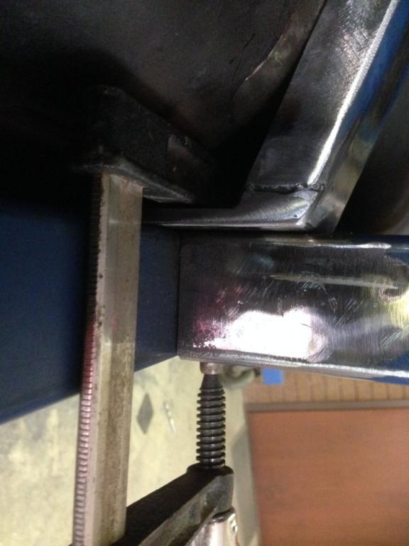
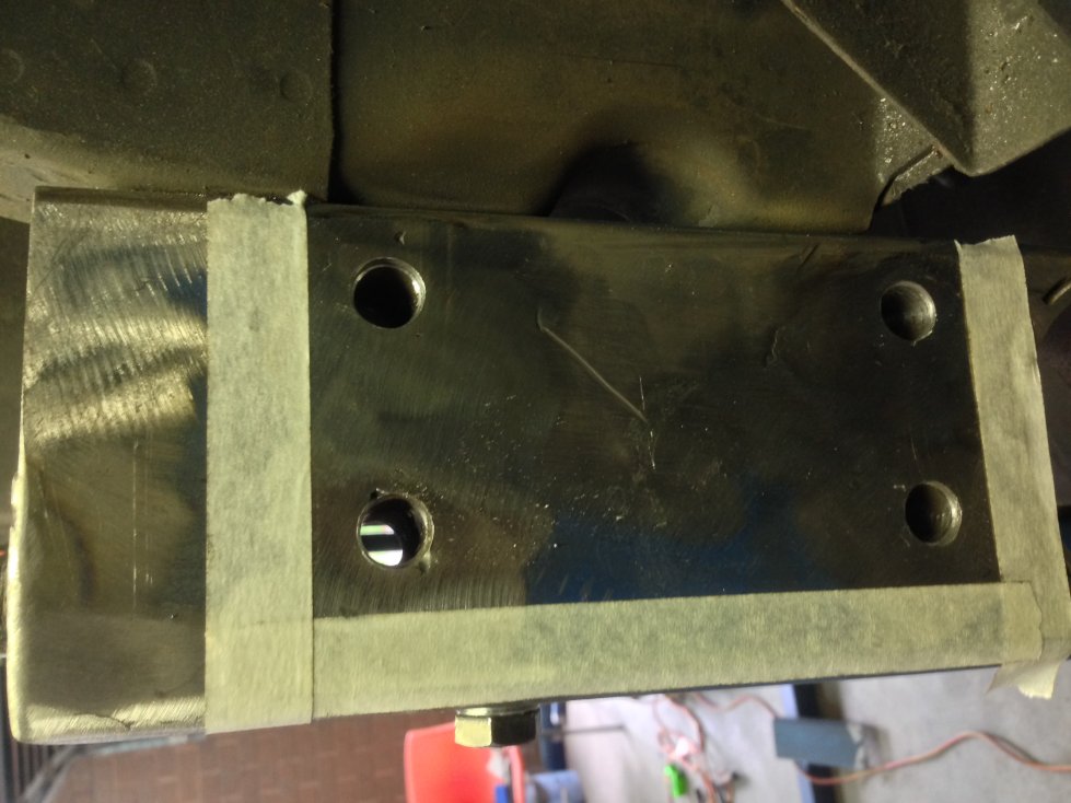
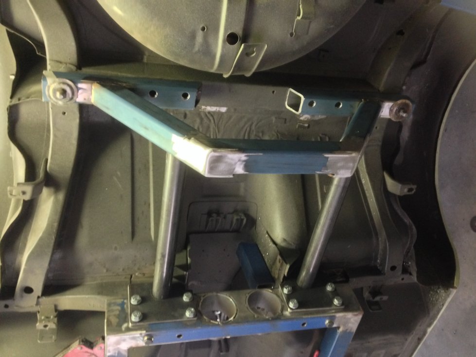
Thanks Buddy I've been cutting everything so far with a 1mm fibre dic on a hand held angle grinder, that is up until today when I picked up my custom laser cut gussets fish plates and LCA hangers. An I did all the CAD work and have all the designs in case you get any ideas LOL I redesigned the gearbox cross member set up AGAIN, and this should really stiffen up the ladder assy, I will now incorporate "X" braces forward and rearward of this assy. The plates were a perfect fit, so I drilled out the fish plates and plug welded them in place, there are still 2 more that need to be plug welded in on the opposite side of each chassis rail but will need to take it off the car first. The corner gussets really start to clean up the look of the assy as did the fish plates, and I am over the moon about the rear LCA hanger plates which I have just sat in place for the photo. Once all these plates and gussets are welded in, I can have all the edges tigged or migged by someone with far more skill than me. Cheers John
-
Thumbs up Maxwell
-
Ollie As you love Turbo L6's Thought I would point you to this Australian 4-0L L6 engine, one of the guys here in Australia who passed away a few years ago shoe horned this motor into his 240Z, The car was never finished but was running at the time he passed away. https://en.wikipedia.org/wiki/Ford_Barra_engine Barra 325T FGX SprintThe final variant of the 4.0-litre inline six-cylinder turbo-petrol engine featured in the FGX XR6 Turbo Sprint. The engine employs an over-boost feature for 10 seconds when optimal atmospheric conditions are met when under full throttle, boosting power & torque to an almighty 370kW and 650Nm. Power: 325 kW (436 hp) @ 6000 rpm Torque: 576 N·m (425 lb·ft) @ 2750 rpm
-
P.S. I am having the rear fully adjustable - all 4 points - (On car) lower control arms made soon, once you see how I have set it up with the new diff cradle I have built, I think it will give you some idea's.
-
Like your style Ollie Shame there is such a distance between us, think we could have a few laughs.
-
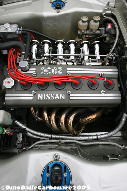
Thanks Olli But mine looks industrial at the moment compared to your fine work. I think its a great engine choice you have there, in keeping with the DOHC S20 L6 in the 432 240Z. It would be interesting to try and have the cam cover restyled so to read Nissan 2000. I know that sounds cheesy but it would confuse a lot of people at first glance
-
Sirpents 260Z / C32 AMG Powered RS30 - Australia
Sirpent replied to Sirpent's topic in S30 Series - 240z, 260z, 280z
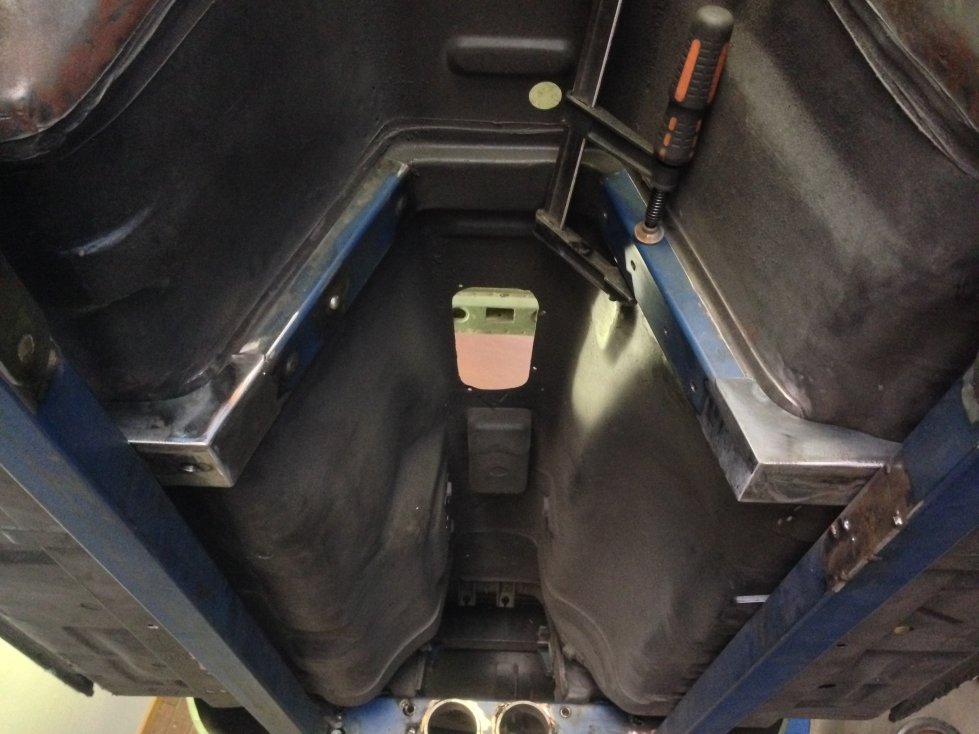
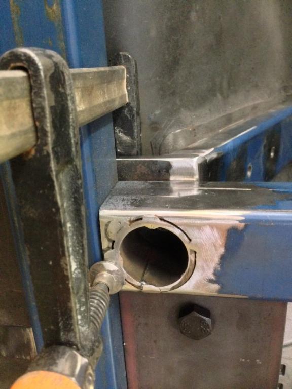
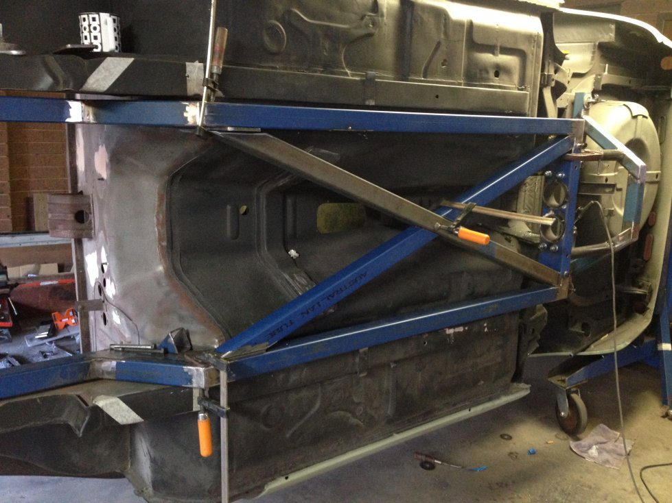
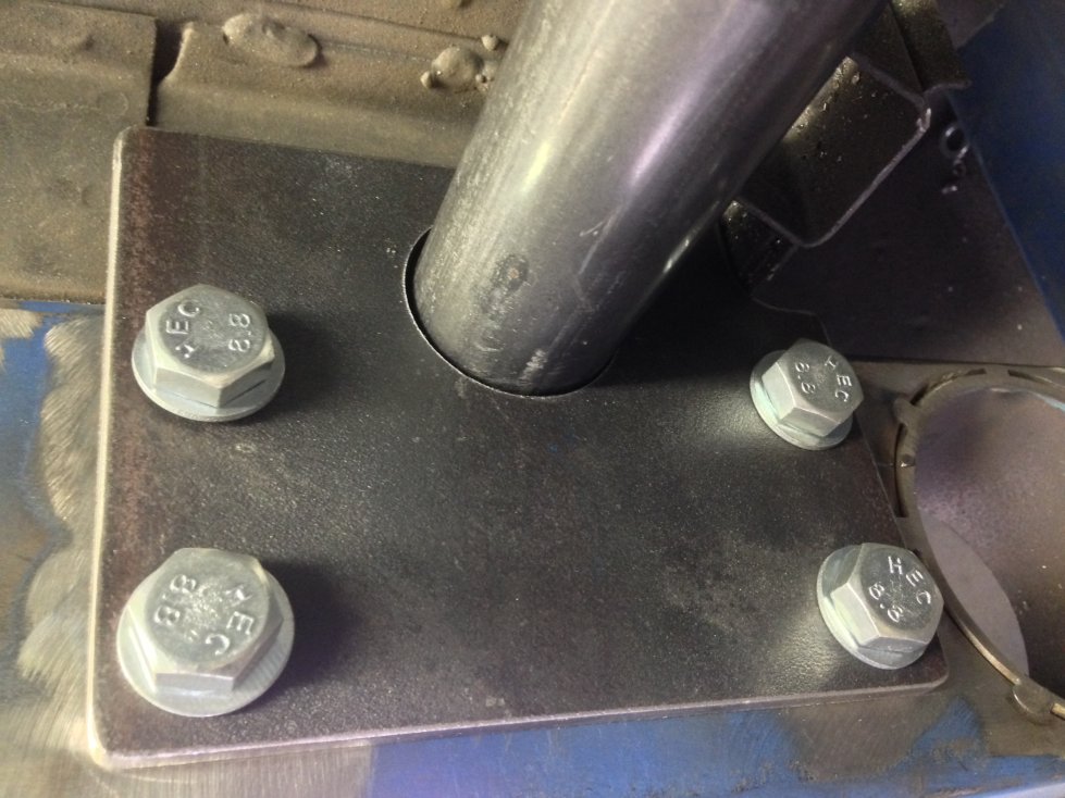
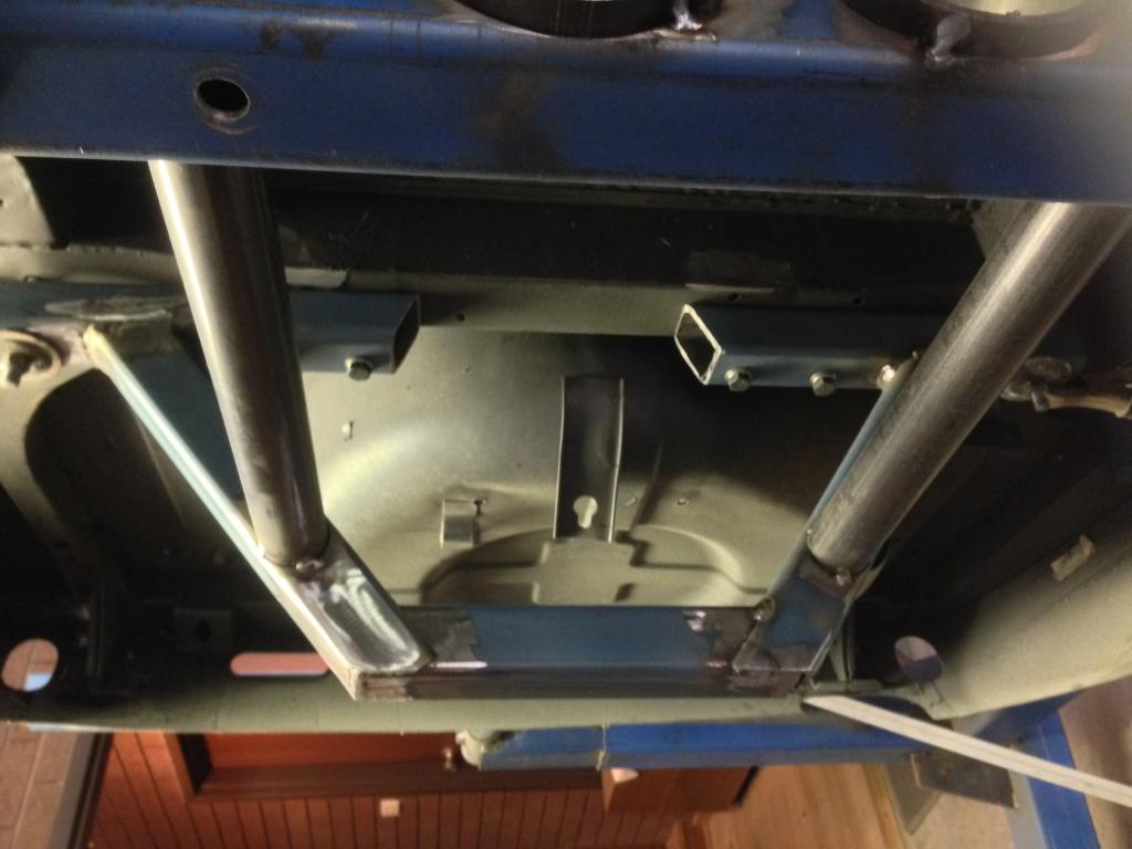
Only 1 photo today, managed to start on the "X" frame within the chassis after a lot of measuring before hand. Seems I have plenty of room all around for the engine and transmission, however the top of the tunnel where the gear shift pokes though will need some minor alterations to get a bit more clearance and the ashtray pod will have to be deleted, guess its time to give up on the smokes Now I just have to wait for the laser cut gussets, fish plates and Rear LCA hanger brackets which should be ready for collection on Friday.
-
Lots Sean.................cars in the paint shop http://www.viczcar.com/forum/topic/4654-kato-kids-bmw-m3-powered-71-240z/page-28
-
Love your work and your engine choice
-
Thanks for the heads up I have a similar problem due to the chassis I'm fabricating and installing and had to look for an alternative that will match inlet and return pipes of the AMG V6 and fit inside the new restricted area. Mine will have to sit above the rails but can take up the full width inside the support area so I'm going with a Mishimoto 3 core radiator designed for a 1979-1983 5.0L Mustang Overall Size: 27.5" x 18" x 2.55" Cheers John
-
Really enjoying this build thread, the skills some people have on here is fantastic including yours. Quick question, that wouldn't be a radiator out of a late model Stang would it? Cheers John
-
Sirpents 260Z / C32 AMG Powered RS30 - Australia
Sirpent replied to Sirpent's topic in S30 Series - 240z, 260z, 280z
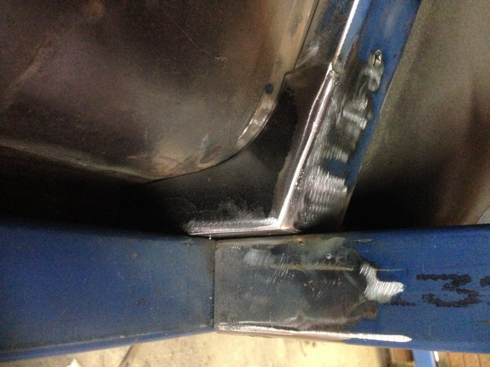
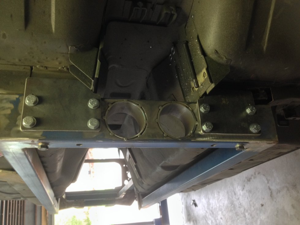
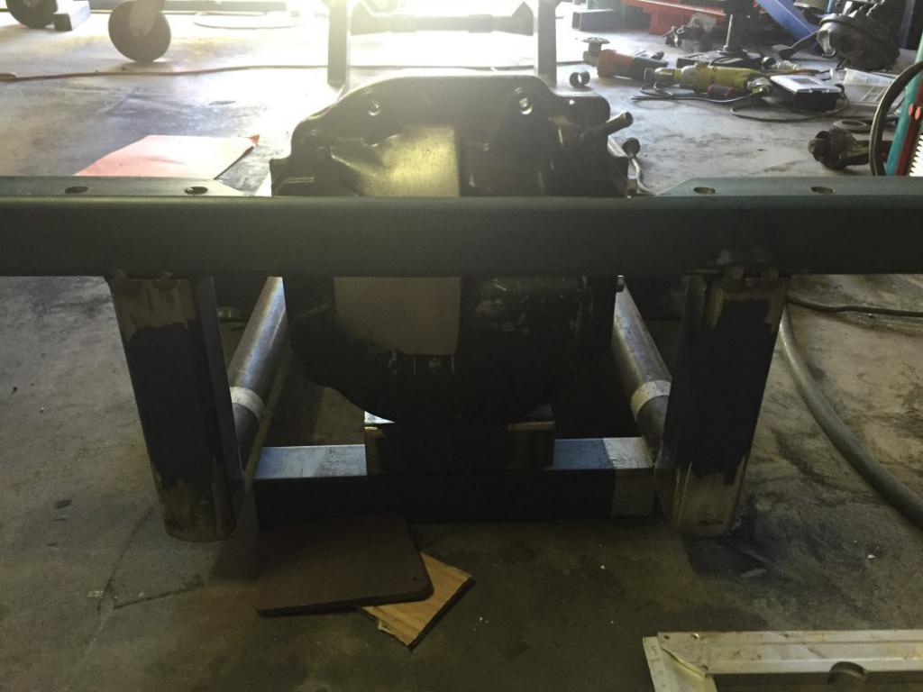
Thanks Boben And it all seems to be coming together now with each section I work on. Finished off all 8 crush tubes today, milled out 42mm holes in the new hanger plates so that the LCA tubes are aligned to the original LCA mount points and then set the lot in place and tacked it all up before taking diagonal measurements to check if the alignments were all in order. Just need to wait for the laser cut LCA and diff forward mount brackets that will slide over the tubes and then I can weld up the entire rear cradle. I placed the diff cap in position just to give an idea of where it will sit in the cradle. I know it looks agricultural, but its all unseen and has a purpose to fulfill, I will make sure the outside interior and engine bay are eye candy Cheers John
-
Stay the path Buddy, you wont always get replies but your work will be admired and inspire others. Treat the thread as a build diary as if no one is reading it, but don't worry, we are As far as your mounts are concerned, there are a load of guys an gals who have done this in Australia, do some surfing of the web and I'm sure you will come across a few build threads on RB20,25 and 30 conversions. Cheers John
-
Sirpents 260Z / C32 AMG Powered RS30 - Australia
Sirpent replied to Sirpent's topic in S30 Series - 240z, 260z, 280z
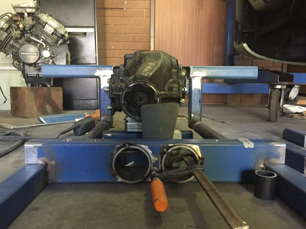
Sometimes you look at something in retrospect and ask "What the F*CK was I thinking" The rear diff cradle and LCA mounts were bad, plain and simple, so out with the old and in with the new. Had some time this week and redesigned and fabricated a new cradle. This one will not be welded to the rest of the chassis which "I am VERY happy with" but rather bolt onto the rearward cross beam meaning. This will really help in the fit up as I will be able to mount the diff as a seperate unit but If i want to drop the entire drivetrain out as a complete unit I can still do that also.. The new set up will now allow me to also use the rear LCA cross brace as a mounting point for the rear diff mount set up. One shot shows the original LCA against the new mount tube. One mount plate and 4 crush tubes knocked over, now the opposite side to do. Cheers John
-
Out with the old. In with the new(er)
Sirpent replied to ehren's topic in S30 Series - 240z, 260z, 280z
Bit of insanity in all of us I see Is that a 302 Windsor or Cleveland you are looking at installing ? In 1991, I actually had a prepped 351 Cleveland (Less intake manifold) sitting in my Z's bay hanging from a gable workshop roof, came in after the weekend and found the roof had flooded over and turned the engine into a goldfish bowl, sadly that was the end of that idea. Cheers John -
Sirpents 260Z / C32 AMG Powered RS30 - Australia
Sirpent replied to Sirpent's topic in S30 Series - 240z, 260z, 280z
Yup, thats about what my Buddies think of me, "Insane" LMAO Thanks ehren -
Sirpents 260Z / C32 AMG Powered RS30 - Australia
Sirpent replied to Sirpent's topic in S30 Series - 240z, 260z, 280z
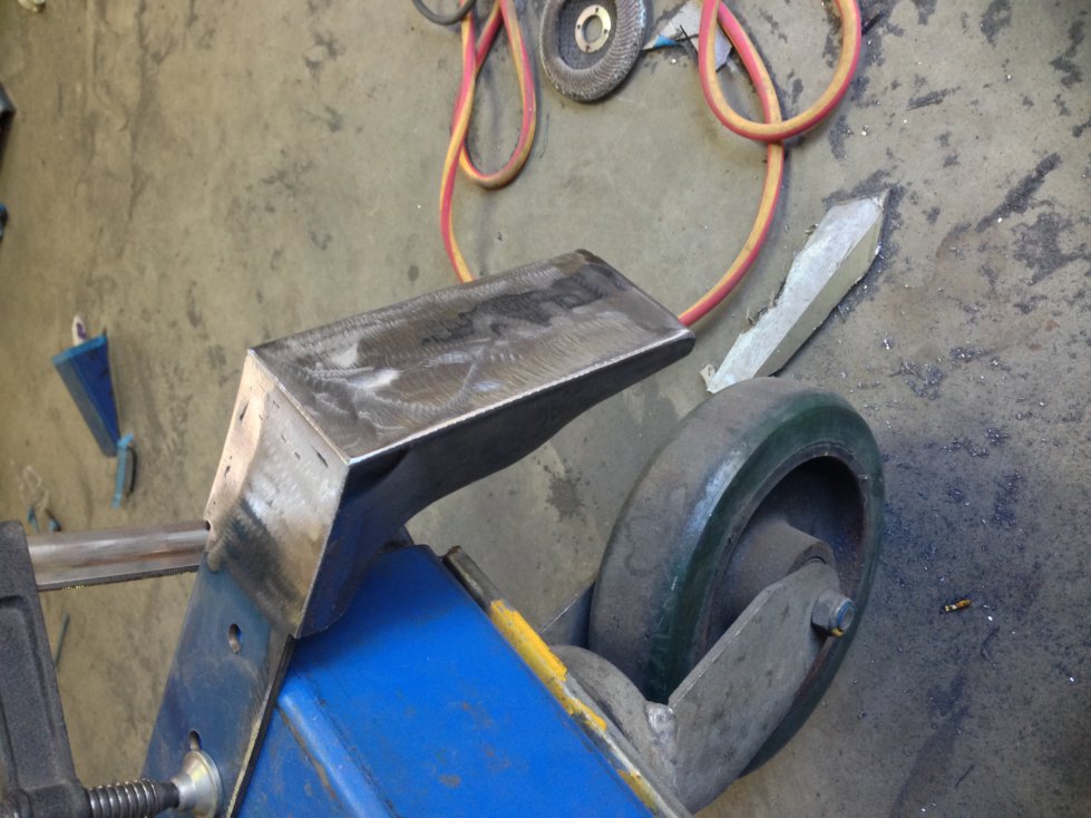
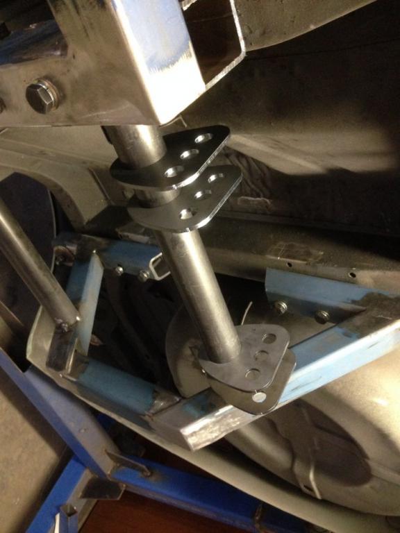
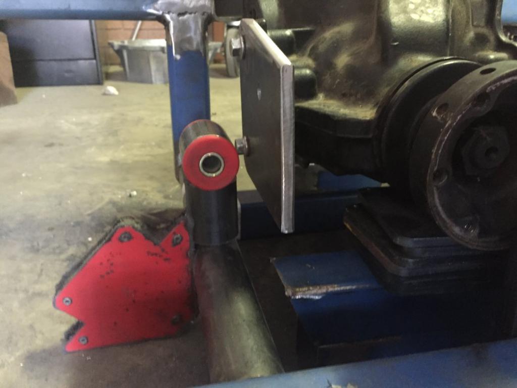
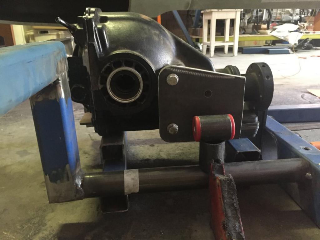
Only a small amount of progress today, both 10mm mount plates cut and drilled, and the RH side mount set with 15mm outrigger to bush. This will still need additional upper and lower triangular gussets set to the plate while the LH side outrigger will project outwards 55mm due to the offset of the diff. This will place both Bush tubes exactly above and aligned to each lower LCA mount tube. Mounts will rise upward from each new LCA mount tube so as to bolt the bushes in place. I need to get the rear diff hat laser scanned so as to build a new cap incorporating the 2 rearward bushes. Same Bat channel next week, hopefully a bit more progress than this weekend. Cheers John
-
Sirpents 260Z / C32 AMG Powered RS30 - Australia
Sirpent replied to Sirpent's topic in S30 Series - 240z, 260z, 280z
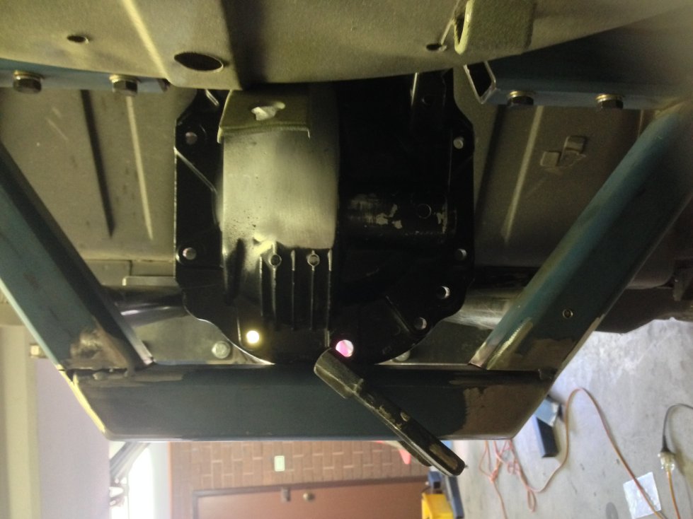
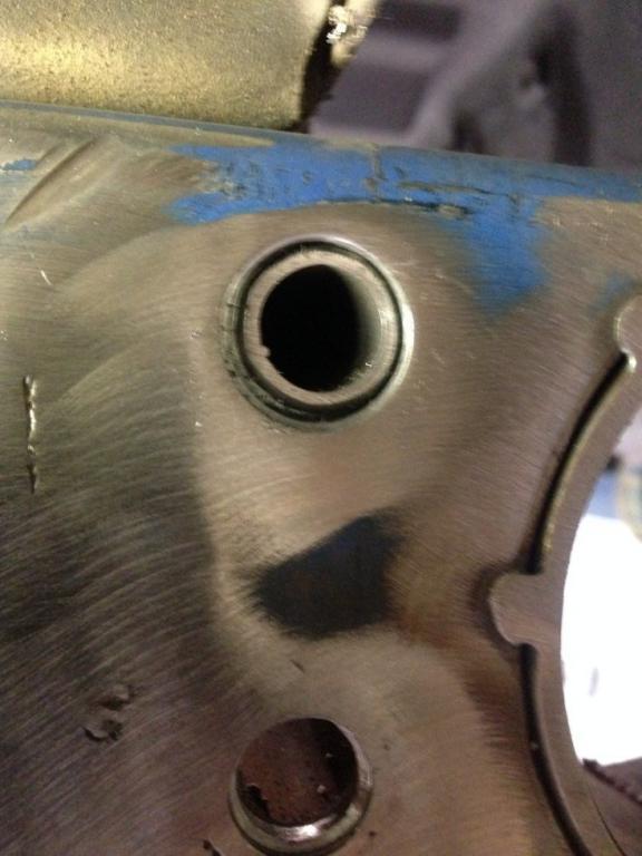
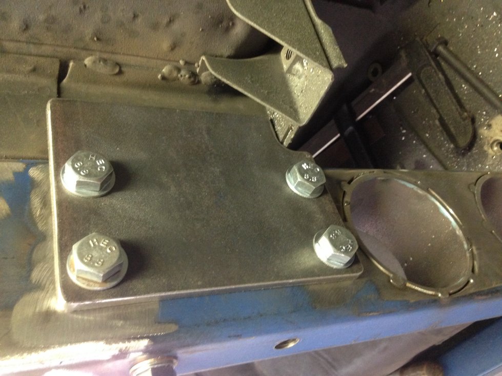
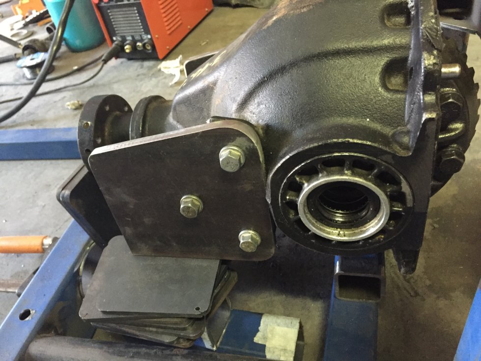
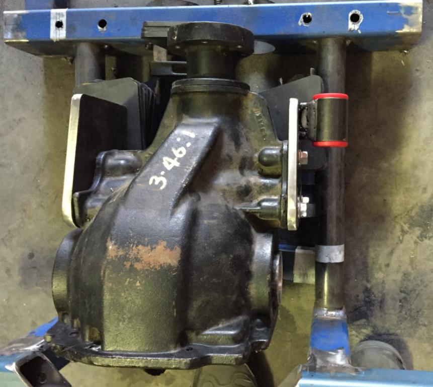
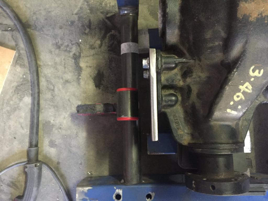
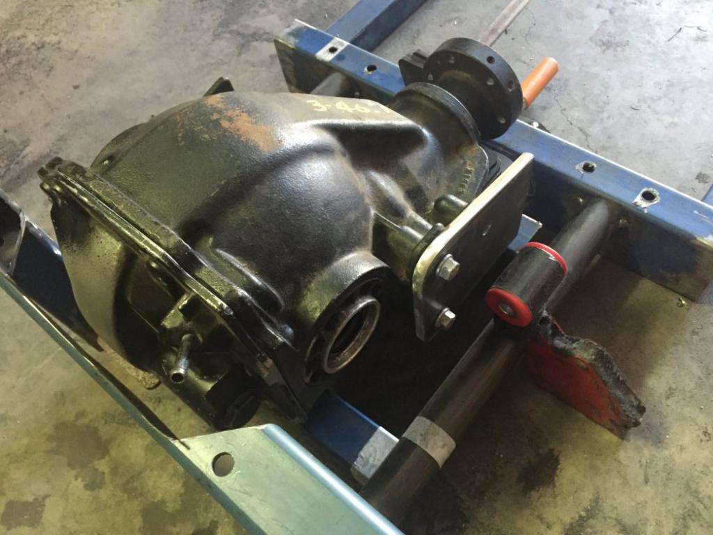
And today........................ Started to square up the diff within the rear cradle. Both diff axle flanges are lined up in same position in space as were the Zeds originals, they may look slightly higher, however keep in mind that the LCA mount tubes are 25mm lower than where the originals sat. Positioning of the diff necessitated cutting into the rear cross member which replaces the moustache bar, no real issue as its 5mm material and I will graft a piece in to close of the box section and double up on the wall thickness now that I can see exactly how and where the diff will sit. Started to fabricate the first Right Hand Side diff mount plate, and sectioned the tube which will carry the nolothane bushes, in the photo you can see the mock up positioning less the brackets coming off the mount plate, think you will all get the general idea. The diff is squared up and sitting on a number of scrap pieces of square tube and plates at the moment, and will be set in the cradle with the input yoke level. The iPhone inclometer is a nice bit of kit and surprisingly accurate, came in handy when I was mock setting the diff positioning. So there are 2 fabricated mounts at the front of the diff, while at the rear I’m looking at using an aftermarket diff cap upgrade Peter Mac put me onto from independent motor sport (see last pic) this should really stiffen up the rear mounting but also still isolate any unwanted feel while driving providing a good level of dampening. Cheers John P.S. Yes I know it all still looks agricultural, but how great it was to work on it all off the body, can’t wait to get to the engine and trans in the future.
-
Sirpents 260Z / C32 AMG Powered RS30 - Australia
Sirpent replied to Sirpent's topic in S30 Series - 240z, 260z, 280z
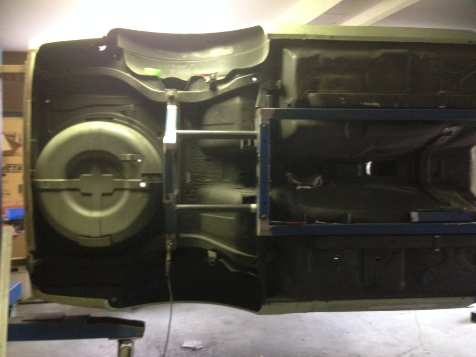
Weekend update So had to drop the chassis out of the car "By myself" as I needed to get to some seams I couldn't get to and I was a bit concerned about the weight, but to my surprise, I estimate around 30kg and not hard at all. Welded them up, lifted it side on again to the car and it slid straight back on and bolted up again effortlessly. With the additional gussets and cross members still to come, it will probably round up around 50kg. Took a pick of the underhang to the rails, as I suspected around 20mm. Next time she drops out, I will be able to start on the diff and gearbox mounts on it. Cheers John
-
Sirpents 260Z / C32 AMG Powered RS30 - Australia
Sirpent replied to Sirpent's topic in S30 Series - 240z, 260z, 280z
Many thanks