

X64v
-
Posts
543 -
Joined
-
Last visited
-
Days Won
1
Content Type
Profiles
Forums
Blogs
Events
Gallery
Downloads
Store
Posts posted by X64v
-
-
You won't regret the JTR radiator, I love mine.
-

It's been almost a year now, but the z is finally going to the body shop on Monday!! The whole rear end will be fixed (sans bumper mounts) and I'm having them replace the rusted-out dog legs in front of the rear tires as well. I'll finally be able to fill the tank up all the way so I don't have to take extra gas with me to the Auto-X anymore.
:willy_nil:willy_nil:willy_nil -
You can use the sensor ground for the braided outer shield. Find some cable with two inner conductors, and use one for power, the other for the signal. Put the capacitor at the sensor between power and ground.
That's basically what I'm doing, but with a single inner conductor connected to the signal pin, the outer braid connected to the ground pin, and the power pin is its own separate wire.
-
Alright, thanks. I guess my next move is installing that capacitor the data sheet calls for. I won't have a chance to get to that before it goes to the body shop though.
How about shielding? I know Xander used a nice shielded cable for his. I'm using shielded cable as well, but I'm using the outer shielding braid as the ground for the sensor (which, from what I understand, negates the shielding effect).
-
arrrggg, they got me... (dies).
-
Well thanks for the lively discussion anyways. If I can manage to get my hands on a scope I will.
Xander, is yours set up any differently than mine that might be the fix?
-
I've got one, comes with piston pin but no rod. PM me your address and you can have it.
-
Oh Braap can I have one pretty pretty please?
And New Zealand? Don't they alread have those on sale there?
-
Then they can make me completely invisible, and I can join them instead of hunting for them in the "Currently Active Users Viewing This Thread" bar.
-
Wow, I almost forgot about my involvement in this thread almost a year ago, in the first few pages... It's been a long year. I lost my title when my donation expired.
I even remember teh original thread name
-
Pin 2 of the sensor is grounded to pin 2 on the megasquirt box. The output pin (pin 3 on the sensor) is connected to XG1.
Megasquirt would not read the 6-1 pattern correctly if it was wired up as per your diagram. Megasquirt needs the opto-isolator to light when there is a magnet in front of the sensor, and be off otherwise. The sensor grounds pin 3 when there is a magnet present, so in your diagram the opto-isolator would be lit except when there was a magnet there, which is backwards. To the best of my knowledge, Megasquirt will not read it that way (at least not with a 6-1 configuration).
Edit: See attachment for my current mostly-working set-up.
-
No, XG1 and XG2 cannot be connected. XG2 is a straight ground for when the trigger input powers the positive side of the opto-isolator. In my case with this sensor, the positive side of the opto-isolator is connected to constant power (5v to OPTOIN), and the sensor grounds the negative side (connected to XG1). If XG1 were connected to XG2, the opto-isolator would stay lit constantly, and the hall sensor would not be in the circuit at all.
I wish I had an o-scope, but I do not.
-
Copied from a chart somewhere else, don't remember where:
16 tooth speedo pinion (yellow) = 3.36
17 tooth speedo pinion (black) = 3.54
18 tooth speedo pinion (blue) = 3.70
19 tooth speedo pinion (white) = 3.90
20 tooth speedo pinion (red) = 4.11
21 tooth speedo pinion (purple) = 4.38
22 tooth speedo pinion (orange) = ?
23 tooth speedo pinion (green) = ?
I know for a fact there are at least three different gear housings, but they're simple to modify so it doesn't matter much.
-
Xander - Looking at your picture below, I can see you have C30 removed, C12 in place, a zener diode in the reverse direction in D2, and I can't make out what's in D1. Is this how it worked, or did you just take that picture before removing those components? I have C30 and C12 removed, and D1 and D2 jumpered.
-
Those were my thoughts on the pull-up resistor, but since it was quick and easy I tried it anyways. No go, it acts exactly like it did in my original post.
As to the overpower thing, I hook OPTOIN directly to 5v, but there's still a 390ohm resistor in that circuit (see here), plus the resistance of the opto-isolator's LED (120ohms) and the resistance in the hall sensor (30ohms). They're all in series so added up they equal 540ohms, which is 9mA at 5v, equalling 45mW. When it's set up like that, it's the exact same wiring inside the box as you have Xander, as far as I know. (Just re-read your post above; yes, R12 is in place)
Edit: z-ya, the anode of the internal LED gets 12v (or 5v) when there's no current, but if there's no ground connection, how can it light? Any interference coming through the external wiring will be on the cathode side, so it could be 100v and nothing would happen.
-
Alright, I'll switch OPTOIN back to s12 via the 1k ohm resistor, and add a 1k ohm pull-up resistor between s12 and TACHSELECT. I'll report back in a few minutes with the results.
-
Will it be okay to put the capacitor about 3 feet back in the wiring? I could put it right on the sensor, but it would be a major PITA and require quite a bit of disassembly.
No, I don't have a pull-up resistor there, I didn't see the point. When the sensor is off (no ground), there is no connection for any current to pass through the opto-isolator, so how could it cause it to light (i.e. where are the electrons going?)? I'm not saying one isn't needed, I just don't understand how it would do any good.
Edit: I forgot to add that the way it's set up now is much better than the 12v source, but still will give me a spike every minute or two, so it's not fixed yet.
-
Ohh, gotcha, I never saw that. I got pretty much all my info from your thread on this a few months back. You used the 5v source to power the opto-isolator; did you install that capacitor as your quote says?
I did a 6-1 setup because I want to go distributorless with MS running a wasted spark coilpack setup (but didn't want all the Ford EDIS stuff when MS can do it itself). I'm running the single coil now just until I get the crank trigger sorted out.
-
Today I wired in my crank trigger set-up, using this sensor and these magnets. I'm using a VB921 to drive a single coil, and the 024s9 decoder wheel setting to read the 6-1 magnet setup in the crank pully. I'm powering the sensor off s12 from megasquirt. The 'signal' pin is connected to pin 24 (grounds when magnet passes by, is open otherwise), and the sensor ground pin is connected to pin 2 via the shielding wire in my DIYautotune harness. In my MS1 v3.0 box I have TSEL wired to OPTOOUT, a 1k resistor between s12 and OPTOIN, and XG1 wired to TACHSELECT. As far as I can remember, I have C30 and C12 removed, and D1 and D2 jumpered.
It runs fine at idle most of the time, and will rev with no load without much problem. But while driving I get tach spikes all over the place, which causes the car to buck and kick. I originally had the sensor powered from the coil positive, but it wouldn't even idle correctly then. Powering it from s12 fixed that. I wouldn't think it could be interference, since it's a 12v square wave. I'll post a datalog tomorrow. Any ideas why I would be getting such bad tach spikes under load?
EDIT: I actually had this set up working a few weeks ago with almost zero tach spikes (maybe one per two minutes). The only difference between then and now is that I had OPTOIN connected directly to a 5v source, instead of through a 1k resistor to a 12v source. These two set-ups give almost exactly the same voltage across the opto-isolator when the sensor grounds the signal pin. I switched it only because the manual at msextra.com says to do it the way I have it set up now.
EDIT 2: I switched OPTOIN to a direct 5v source like I talked about in edit 1, and now it seems to be working fine. I guess the question now is why?
-
Insurance wont cover the tires since I've only got liability, but I think I might be able to squeeze this one under the road hazard policy I got from discount tire
I might just have a hard time explaining how I got about four screws in each tire...
Don't tell and they won't ask, and they will replace them. My roommate works for discount tire, he says he's seen the weirdest things (like a spoon one time).
-
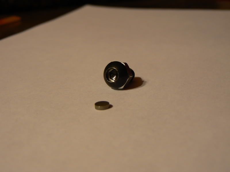
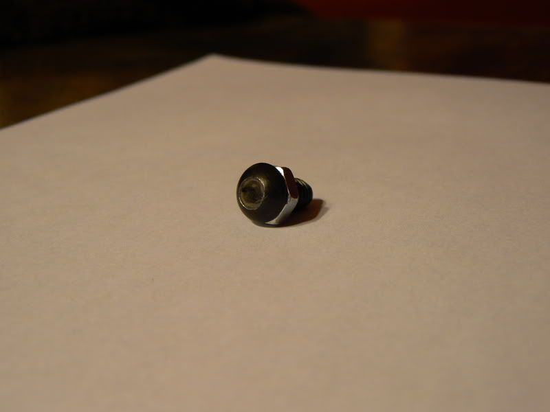
More progress on the crank trigger set up. I've actually had it together and working, but for reason's I'll detail later I'm back on the VR dizzy for now. These are the magnets I used. First, for positioning the magnets, I used the six evenly-spaced threaded holes in the front of the ZX crank pulley (you can see them in one of the pics above). I took button-head allen screws, locked a jam nut up against the head (with red locktite to be sure), then drilled out the hex to ~.005" greater than the diameter of the magnet. The magnets are held in with JB Weld to be sure they stay.
The nice thing about setting it up like this instead of using allen-head cap screws is that I can fasten/remove them with a 12-point 10mm socket, instead of vice grips or the like.
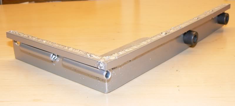
Below is my original mounting bracket for the sensor. It's 1.25" x .125" steel (just leftovers from another project). Turns out that this one wasn't stiff enough, as at about 4500rpm it flexed enough for one of the magnets to come in contact with the sensor, completely annihilating it (on the way to school, no less, forcing me to walk the rest of the way to class). Bear with the weld splatter, I only have access to flux core.
To reinforce it, I used some 1/4" solid square stock. I also added some 5/16" x 2" roll pins through which to route the wires so they can't get caught in the fan.
Most of the ideas and hardware I got from this thread. I won't be detailing software settings or how to wire the MS board in this thread. If you're doing something similar you can PM me about the details or check out the hardware/software manuals at msextra.com.
-
Those are such sad pictures.
I never ever want to see my 240 covered in snow or ice.But it was 81°F and sunny today, so I don't think I have to worry about that.
-
I have one, out of car. what would be the best way for me to get the ratios so I can post it up.
Easiest way for me is to use an old clutch disk, make a chalk mark on it to count revolutions (usually starting from straight up), and make a chalk or sharpie mark on one of the splines on the output shaft and on the seal near it. Put it in gear and count the full rotations until the output shaft makes one full revolution, then guess at the angle of the chalk mark on the old clutch disk to approximate the ratio (i.e. 2 rotations and the chalk mark 3/4 of the way around would be 2.75:1)
-
And take a look at a ot of Metallica's older stuff. A lot of those are songs that they didn't write (Whiskey in a Jar, and Bob Seger's Turn the Page for example).
Those two songs only appeared on one Metallica album, Garage, Inc., which was specifically a cover album. They didn't try to take credit for writing any of those songs.
I'm staying out of the Led Zeppelin debate, just wanted to set that straight.

 :willy_nil:willy_nil:willy_nil
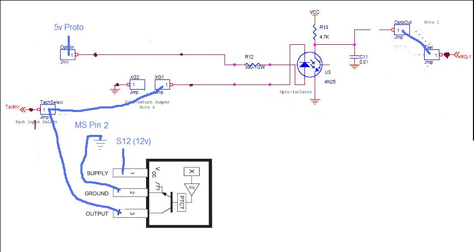


hpi racing RC Zcar
in Non Tech Board
Posted
This makes me want to get my RC truck out soooo bad. I've got a Revo with the 1" extended chassis, all titanium pins/rods/balls, EB Mods OS .18 TZ, aluminum knuckles, etc etc etc. I bought it used ready to race, then started sinking money into the z and haven't touched it in three years. I keep thinking about selling it, but I know I'll just buy another one when I get out of college so I've kept it.