Dershum
-
Posts
147 -
Joined
-
Last visited
Content Type
Profiles
Forums
Blogs
Events
Gallery
Downloads
Store
Everything posted by Dershum
-
That wouldn't be the dude that owns the Lynne's Nissan dealerships would it? I've seen their Z storage (or at least one of them) downstairs from their service center in Stanhope. It's a z-gasm down there.
-
This is awesome! Any chance of the outside dimensions, and possibly the cross-section to show the depths of the "bump" and the outside ridges?
-
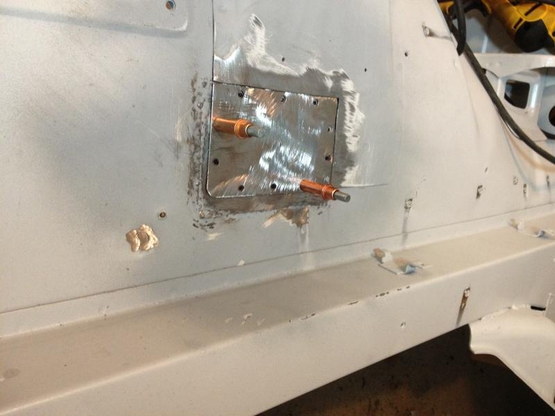
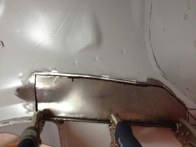
I'll try to remember to take a pick before I burn it in. There was rust through both layers of the passenger-side strut tower (and driver side that I haven't touched yet). I cut both layers out, and had already welded a patch to outside-facing side. So that panel is the engine bay side of the passenger strut tower, just south of the cutout in the body sheet metal where the strut/spring goes through and up to the upper mount. I cut the panel and then popped holes in it with a cheap panel flanger/hole cutter that I got from Harbor Freight, so that I can plug weld the panel to the one behind it as well as weld around the perimeter. There's only two holes (where the cleco's are) going through the panel underneath.
-
Tony, thanks for the guidance. I've already got some solid ratcheting straps to use, and I'll just got the tire route. Thanks again, and I'll let everyone know how the move goes!
-
I've searched the site, other Z sites, and the interweb high and low, but I've not been able to find these. I'm planning to pick up my engine from the builder over this coming weekend, and was originally intending to simply strap it down to a tire in the back of my truck and drive it home. But since home is about 400 miles from the engine builder, I'm starting to think that putting together a simple crate to more securely move the motor in might be a better idea. That being said, I don't have the engine easily accessible to take these measurements, so I was hoping that someone could help me out. I've put together a little diagram of what dimensions I think I need to make a simple wooden frame to put it in and strap it into for the move. Oh, and to caveat the motor, it's just the block/head/oil pan/valve cover. Trans and all the various accessories aren't on the block, so it's pretty bare. Any help would be greatly appreciated!!!!

-
Great googly-moogly! That's the cleanest garage I've ever seen! Amazing build too...where on earth did you find tail lights that nice?
-
A little more progress. The inside of the passenger strut tower (the outside was in the first post) ready for welding. Got to play with my new cleco's that I got for my birthday! It's amazing what having the proper tools (got a cheap benchtop belt sander) can do for fabrication time!
-
I was primarily using it for the area I was plug welding to, since the metal was going to be overlapping and I was hoping for some rust protection between the layers. It'd be kind of hard to get just the plug weld spots on the underlying metal clean while leaving enough of the primer to make it worth the effort tho. I'll probably just skip it going forward.
-
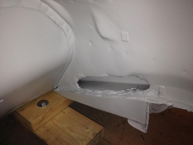
I had to remove that much, since the rust hole went that far forward...there was a pretty big gap there. Here's a "before" pic of the same hole on the passenger side. The driver side one was a little longer. I managed to get it welded on finally, and it's looking pretty good. Still have to grind it tho. The lessons learned here were: 1. Weld-thru primer is a lie. 2. ALWAYS re-check your welder settings. My wire feed speed had mysteriously been turned WAY up, I think when I moved the welder after doing my tests. Once I set it back down, things went much more smoothly.
-
@mditt8671, I was just bending the patch panel. There's what looks like an intentional bend in the sheet metal (this is the driver inner fender area, just forward of the firewall along the frame rail), so I bent the side of the patch to match as closely as possible. Best I could do with a small vise that had an anvil plate on it and a hammer. @Zinpieces, nope...no magnets involved. Just the vice grips holding the bottom lip of the patch.
-
I was thinking about cranking up the voltage, but the test welds I did came out just right so I figured I had the settings pretty close...plus I don't want to blow through the sheet metal on the body...had that problem with some previous welds! I'll give sanding the primer off a shot and see what happens.
-
Not to necessarily self-bump this, but I was hoping one of the folks out there who are a bit more of a welding expert might be able to help me out a bit. I started welding on my new patch after spraying the area behind the patch with weld-thru primer, and also painting the back of the patch with the same primer. It's that Eastwood self-etching stuff. When I did some test welds against an old piece of the body that was cut out, and a piece of the same stock I made the patch from, I simply sanded the piece I was welding to, and proceeded to do a few plug welds to weld the test piece flat against the old piece of body. Everything went great. Then when I started welding the patch to the body, the wire from my MIG started "skipping" around a lot when I was trying to weld. The wire started by coming out, the arc would start, and the wire would "hit" the metal, and either break off or skip around...it was like it was a partial arc or something and I just couldn't get a clean weld. It rode very proud on the plugs and I wasn't able to get any penetration. I'm guessing this probably has to do with the "weld-thru" primer, so I probably just need to sand off the area and try again with clean metal instead of trying to be fancy with it. But I wanted to throw it out there and see what folks thought of the issue. Any help would be greatly appreciated!
-
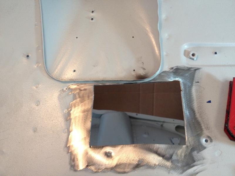
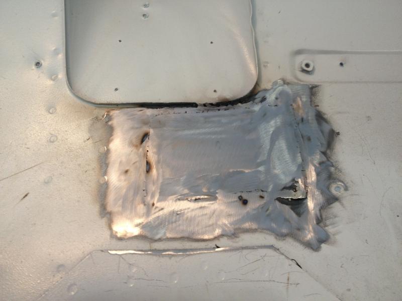
I just thought I'd post a little of the progress I've finally managed to make on my patch panels. It's taking forever to get through these, but it feels good to have a little bit of progress finally! Before After And another in progress
-
Lol...already changing projects? I keep getting distracted because it's so damned cold out in the garage and almost starting new ones...gotta stay focused. Putting the spreader bar on helps immensely with moving mine around. Even if the engine stands are stable on their own, there's flex in the heads where they connect to the body and a little bit in the body itself so there's a lot of "give" when trying to move it. Putting the spreader on locks the stands together and makes moving it far easier. It also occurs to me that this thread probably belongs over in Fab/Welding...hopefully a mod can move it.
-
Might I suggest you connect the two engine stands together using some square tubing? Here's kind of what I did: I just took a piece of angle iron and drilled holes in it so I could bolt it to the engine stand front crossbar, and then welded a piece of square tubing at a 90 degree angle to that. Wash rinse repeat for the other engine stand. Bolt those on, and then slide a smaller diameter section of square tubing into the two cross bars. A hole can be drilled and either tapped or a nut welded to the new larger-diameter crossbars so you can use bolts to tighten down the sliding section of tube. I did it that way so I could adjust the stands distance from one-another as necessary.
-
Show Off Your Engine Bay! Pics Wanted, L-series
Dershum replied to philipl's topic in Nissan L6 Forum
What is the black wishbone-shaped doohickey on top of the valve cover? Some sort of clip for holding the plug wires? -
Couldn't one hypothetically run those three lines together into a single line, and then vent it to the top vent tube on the fuel filler tube? That would solve the problem of not allowing the tank to fill all the way. Then replace the gas cap with a vented cap so you don't get a vapor lock in the tank while the car is running? The only problem I can see with it is possible fumes into the car from the vented gas cap. I don't recall how "sealed" the gas cap area is, so the fumes vented through the cap could possibly get into the cabin of the car. Again, this is just theory, but I seem to recall reading something to this effect a while back, and I've been trying to think through how to eliminate the vent line that goes forward into the engine compartment from the vapor canister so I don't have to run that extra line. I seem to recall someone mentioning that it could be connected to a coiled line that as long as it was higher than the tank, it could be safely vented to the atmosphere under the body of the car.
-
I'm finally starting to cut out the rot on my 240 shell and weld in patches, but as I get closer to some of the bigger jobs (floor pans, rocker panels, etc)., I got to thinking about the order I should do these things in. So I figured I would ask! My original plan was to start at the front and work my way back. Cut out a piece of rot, weld in a replacement patch or new panel. Some of the repairs are cutting out rot over the front frame rails inside the fender wells or in the strut towers. I'm starting with those, and then I was going to start tackling the bigger jobs like the rocker panels, floor pans, inner/outer rear arches, and then the hatch panel at the back. For the small rust patches, it's pretty straightforward, cut out the rot, make a patch panel, weld it in, wash-rinse-repeat. However, for the rockers/floorpans I'm trying to decide how to proceed. There's some rot in behind the rockers at the back, near the inner rear wheel arches. I figure I need to cut that out and replace it with the new inner wheel arches before I can replace the rockers. But to cut that out, I need to remove the rocker panels (obviously), which I would imagine need to be in place on the car (even if they're rusted) before I try to replace the floorpans and frame rails. So my current order of operations (yep, there's the nurd in me) is as follows: 1. Front strut towers. 2. Fender wells on the outside of the frame rails (I can provide pics if this doesn't make sense) 3. Floorpans 4. Frame rails (bad dog) 5. Cut off rocker panels 6. Cut off rear quarter panels 7. Cut off inner rear wheel wells (once I get the replacement panels...still waiting for them to come off back-order) 8. Weld in new inner rear wheel wells 9. Weld on new rocker panels 10. Weld on new outer rear quarters 11. Hatch panel Thanks all!
-
Identify this part and one more thing!
Dershum replied to 280z4me2's topic in Brakes, Wheels, Suspension and Chassis
Not to threadjack, but something I've been trying to confirm...the strut insulators on the 240z, are they interchangeable front/rear? -
Do you have any pics? I'm going to eventually have to tackle this and I'd love to see pics of the different options.
-
Like this http://forums.hybridz.org/topic/109244-how-i-removed-my-insulation/?hl=dry+ice
-
So kind of like the ones that Black Dragon has in their catalog then, which is what I kind of thought they were. I was going to go the buy-a-roll, flare, and bend myself route, but since I've never flared brake lines, and I've seen enough horror stories about straightening brake line from a roll, I figure I'd like to avoid as many potential points I can royally screw it up as possible Once I get to the point I'm making brake lines, I'll be sure to post up how it goes. Gotta finish metal work on the body and get underbody coating and interior coatings done, then I'll be looking at stuff like brake lines. So sometime in the next geologic eon most likely
-
Were the lines just straight lines with pre-flared ends on them, or were they bent already? I've got to replace all of mine, and I'm trying to decide what the best way to go is.
-
Ditto...thems are smexy.
-
I started that way, but it left way too much residue that would have to be ground off after chiseling. Even with the dry ice, there were areas that just didn't want to come off that I really had to fight with. I also tried wire wheels on an angle grinder...giant mess. and for about 1/2 a sq foot of insulation removal, I tore through about half of the wire wheel. And it was one of those "heavy duty" ones with the strands woven together into about a dozen thicker "ropes" around the circumference of the wire wheel. I considered a propane torch and a paint scraper, but 2nd degree burns from melted rubber didn't particularly appeal to me. At the end of the day, it came down to 2 factors. 1. I'm fat and lazy...the less manual labor involved in an effort, the happier I am 2. I don't get nearly enough time to work on the car as I wish, and doing it this way let me get all the insulation off in 3 hours. I'd imagine that might be possible with a chisel and hammer, but damn...I think my arms would fall off before I got 3 hours into it at that pace As Scrooge McDuck would say...work smarter, not harder!