
Daeron
-
Posts
2148 -
Joined
-
Last visited
-
Days Won
2
Content Type
Profiles
Forums
Blogs
Events
Gallery
Downloads
Store
Posts posted by Daeron
-
-
But did you use jbweld to fill in 2"x1" holes? Sure its fine for the little bolt holes that dont go all the way through but...
Thats what the good Lord invented Wire Mesh for.
-
All I could think of was, many pages back, someone said "what kind of exhaust manifold are you putting on this engine?" and you posted a pic and the reply was "Oh good grief!!!"
Cue the Exhaust pic!
-
Challenger, are those the runners from the diesel intake? or is that just something... else?
-
A bit of welding on the ends to accept a plenum, and there is no requirement for this to only be N/A...
Though seeing a custom-cast ITB N/A setup that puts TWM to shame really does have it's allure...

Anybody remember the old CAN-AM or Formula cars with their stacks all askew? That's what this reminds me of, I love the look!
The performance and sound are frilly intrinsic benefits for motorheads!
I've been thinking the exact same thing since I saw his design, but couldn't recall which cars they were
-
Don't necessarily lump the 280ZX comments into the category of "you should start out with such and such a car."
That is not the intent behind, at least, the more informed people mentioning that point; the intent there is to inform that the aerodynamics on the S130 are superior, and any attempt to emulate the changes made in the S130 revision, onto an S30 chassis should pay off.
The fact of the matter is, last summer the do-it-yourself Z-tuning world was blown away by the round of aerodynamic testing that was done on numerous S30 body setups. The impacts of that knowledge are still being felt widespread, and people are pointing those facts out to you. GRANTED, it seems like you are getting more of the "just buy a honda and don't ruin your Z" than the spirit of the place should suggest... but, as I said, don't lose sight of comments that detract from your idea if they point out room for improvement.
I still say get a 4 cylinder L-series, and get the extrudabody twin TBI/SU replacement kit. http://www.extrudabody.biz/servlet/the-135/Twin-SU-SU%27s-MGB/Detail
$545 for the entire fuel injection hardware, get a MAP and some megasquirt, you should be fuel injected for $1000-$1200.
-
I KNEW it had to be commercially available!!!!
I just might take the time to delete all the CA and AT stuff off of my 75 diagram and do that.. must look into this further, thanks Prox!
-
Okay, so I have gone and pored over my wiring diagrams and the actual wiring of my car, and read my write-ups, and I went and obtained a Maxi-fuse block from a Cadillac in a local junkyard. (nice score, I'll snap some photos and post the specifics when I get my car running
) The block I got has five circuits on one common "gang" feed (cable lug) and one isolated circuit with wires going to each side.In examining my diagrams, it seems as though the 75 system NEEDS the "divorced" circuit protection... but once I look at the wiring of the car, I begin to doubt this. The old fusible links literally burnt in a mini-catastrophe, and I am finally getting to repair the damage by way of installing this block. (I also have an internally regulated alternator to go in, and relays to install, and plan on re-engineering half the electrical system in the car)
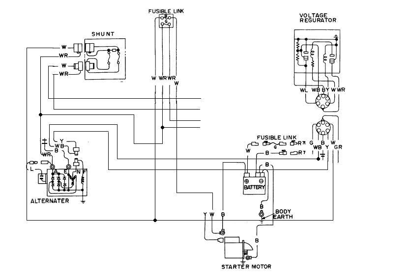
This is a cut-and paste representation of what the FSM wiring diagram says I should be expecting... The several wires that go "nowhere" in the center of the image all go into the cabin in the main engine wire harness right underneath the battery tray.
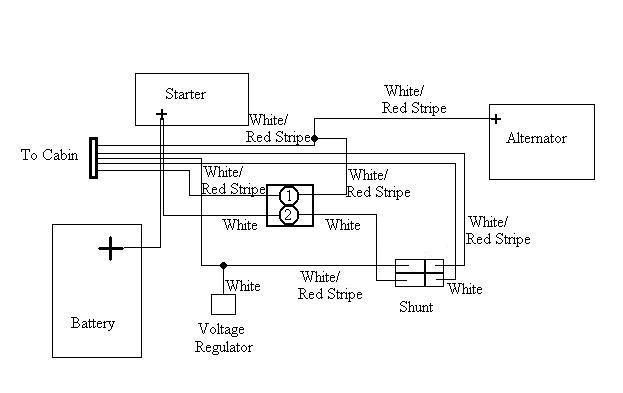
This is a sketch of the circuit as actually wired, factory original (as far as I can tell)
The primary difference between the two diagrams is that the small white wire going to the regulator is, in reality, tapped off the large WR wire coming out of the shunt. The slightly longer boxes of the shunt plug represent the larger wires.
Forget for the time being the apparent difference in the voltage regulator (regurator,
).. I can deal with that part. The fundamental stumbling point I have here is, well, difficult to wrap my brain around enough to explain.Okay, there is a large WR wire coming off the alt charging post. It originally split into a Y below the battery tray, sending one leg on in to the cabin, and one leg up to the engine side fusible link (green, correct? 50 amps.) All WR wires. The WR wire that came out of that fusible link, also went into the cabin. The other fusible link (fender side, black) was between the white wire going down to the positive battery terminal on the starter, and the large white wire going into the shunt. The large WR wire coming out of the shunt, also went into the cabin, as did the two small wires (W and WR) coming out of the shunt.
What I *DID* tonight, was install this maxi fuse panel with crimp connectors.. I didn't want to alter the vehicle before remedying the problem that sidelined it, but I had to start somewhere and replacing burnt wires was step one.
I cut the alternator charge wire off of the Y junction where it met the wire going up to the fusible link. This left me with two separate wires, hitherto referred to as "charge wire" connected to alt, and "main wire" going back into the cabin.
I spliced the charge wire into the "divorced" circuit on my fuse panel. This is what I was uncertain about.. which circuit to leave "divorced." The output on this circuit was linked back into the original output of the fusible link, a slightly smaller gauge WR wire, going back into the cabin.
The wire that had previously routed from the shunt up to the fusible link, thence into the battery, got a cable lug on it, and got bolted to the "main" feed of my fuse block. I then attached the wire going to the starter (W) to one of the 5 outputs of the maxi fuse panel.
I connected the "main" wire to one of the other panel output circuits.
So I connected the battery. The right turn signal stuck on (regardless of key) and the headlight/taillight/panel light functions normally, except again, they will turn on or off, regardless of key. And nothing else worked at all. Okay, so I have unspecified problems.. whatever, I will conquer that later.
What I am having difficulty understanding is.. it seems like one fusible link is there to keep the battery from getting cooked, and the other is there simply to fuse a portion of the alternator output current.. and the rest of the alternator output current is fused before it gets sent off to its various domains? The literature I have consulted all seems woolly on the whole affair. Naturally, the 75 FSM that is now available for download... is missing the BE chapter. I try to make do with a 74 and a 76 BE chapter... but it isn't the same.
In my head, here is what I see as needed.
Battery, wire to starter. Wire to Fuse, to charging wire of alternator. Fuse between alternator output and, well, everything else on the car.. So I guess what I am asking is, can't I set it up, just like that? To me, the alternator charge wire is the primary source of amperage for the system. So, the alternator output should be considered the highest current circuit. Fuse in between that and battery/starter, and then anything else is just a matter of installing a fuse of a given rating.. if some of them have to be fusible links or maxi fuses or aircraft circuit breakers, whatever.
Can you tell I am hopelessly confused by something that I thought was going to be elementary? Does ANY of that make any sense? Am I actually just making a HUGE fuss over a slightly less-than-clear situation? I can see how this might be WAYYY simpler than I am making it.. but I can see so many ways I could be misunderstanding something, and so... I just dont know!
With any luck, going back out tomorrow and looking at it under a new sun will suffice to clear my head.. If I am not mistaken, I am simply emulating one of the additional fusible links on the 4-link setup on 76-78 cars. Is the fourth link in that setup a replacement for the FI fusible link that comes straight off the battery wire???
-
Because the throttle bodies come in at different angles along the horizontal plane, having horizontal shafts would be a real pain to machine. And besides I love the look of the linkage on the top.
:hs::hs:all I can say to that is DUH, I knew the answer was simple and obvious but it frankly didn't occur to me when I asked myself the question...
-
the 240 might yet be desirable to someone....
I would build your 76, keep your spare parts, and (if the front of it is worth it) try to sell the 78 and the 71 together to someone with the intent of making one solid car out of two. A rust-free 240Z is something to be desired.. just don't expect much $$ for the two cars. Depending on what your buyer wants, it sounds like you can get him a mostly complete car from the spare parts without hurting your own stash of spares.
What kind of soobie, EA82?? I drive an 87 GL-10 sedan
-
There are still PLENTY of high-quality tire models (I don't want to use the term "series" because that gets confusing when talking tires) that are available in 14 and 15 inch sizes.
One clue to help you in your search; when you go to tirerack.com, there is an option to "See other sizes this tire comes in." That is probably not exactly how its worded.. but its damn close. Click on that link, and find the outside diameter of the stock tire size (cannot recall right now.) Then, find the biggest tire you can that will fit on a 6" wide rim, that has that same outside diameter.
This keeps your performance tires spinning your speedometer the same as the stock tires, and also ensures stock clearance inside the fenders. IIRC, 15" tire size that matched stock OD was something like 195/60, maybe 205/60.
Also, Toyota Supras came with a four lug rim that looks like this:
that measures 14" diameter, and 7" wide. That gives you the ability to put some more rubber underneath, and I do NOT think you need spacers with these wheels... If you do, then simple 1/2 inch plates behind the wheels suffice, no need for expensive adapters.HTH
-
Hey, you should make a single post titled "S30 Factory Service Manuals and More" so we can nominate it for a sticky here.
I would do it, but I don't wanna steal your thunder.. and any of these individual posts are less than ideal because they are each model-specific.
-
Beautiful photo!!!
-
The simplest route is to get custom pistons made to match L24, 133 mm rods. I forget where the link is, but i *think* a company stateside like Jeg's has a deal to get a set of Ross Forged pistons on the CHEAP, something like 4-500 USD. The secret is just order pistons with the specs you need, and don't tell them it is for this engine or that engine.
This would also allow you to bore out to 89mm if you would like, to get up to just over 2.9 liters.
The way I have come to look at it, the pistons and the camshaft are probably the two most important internal engine parts to swap out to aftermarket on a custom L-series build, when serious power is desired. Rods are good (to a point) crank is good (to a point) but the camshaft is a no-brainer.. and in my mind, so are pistons. Get custom pistons cut SPECIFICALLY to what you want. Between the pistons, the cylinder head selection, and the camshaft, you have your engine. Block selection, crank selection, rod selection.. thos are all easy, all stock parts can be used, and all are essentially a matter of either taste, or what you REALLY want out of the motor.
I keep playing with the idea of trying to get one of you Ozzies to ship me an L20A crank to build a DE-stroked L6... I just have to convince myself that I really don't mind poor low end power on a streetcar that could run up to 8000 RPM...
BUT, thats just an option. The cam and the pistons that go into the motor, really should be determined by the rest of your "options" combined with your goals.
-
i kno alot of ppl have a problem with understanding the swap from a s-130 to a s-30 and its very easy, but when you gat down and do it the wiring is a pain in the ass litteraly and ppl cant help and explain it so i will explain it so every one knos,
ok so the main thing to kno when wiring in the harness is there are two seperate ones. One is the FI harness and the other is the igniton harness
well all you have to do is connect the green and brown wires off of the FI harness to power ok, then hook up the EFI relay to 12v switched power right and this is the b/w wire and you connect that to the blue/red wire in the little plug bu the brown and green wire there is five wires in that one plug but only use the b/w and blue/red,
now for the ignitor and ignition harness only use the b/w wire again and the yellow wire, and DONT cut the yellow/white wire that goes to your ignitor, so the yellow wire goes to the starter signal wire, and the b/w goes to the blue/red wire
and thats it, an easy way is br and g go to 12v, b/w from ignitor and from EFI relay go to blue/red wire and then hook up your own fuel pump relay, and it will work ill post pics later
without editing any grammar or spelling, no added punctuation.. just hitting enter a few times.
I am just showing you how much easier it is to read your words with a few pauses in between, compared to your original post. When someone did this to me the first time I felt like a complete doofus for not having noticed how much easier the second version is to read.
You have an excellent point; the wiring conversion is NOT incredibly complex. This is a GREAT subject to write a concise post about, and you've done a good job starting it.. but re read it when you get pictures to post, and tweak it a bit to make it easier to read. I couldn't even find the end of a sentence to use to hit "enter" on, so I just stuck em in there somewhere that seemed reasonable.
I hope you are getting the point that I'm trying to help you be more helpful to the rest of us; nobody likes a Grammar Nazi but nobody likes to read sentences that just go one forever because really they do tend to get annoying and keep you from using such an excellent resource as hybridZ, which is an awesome community founded and maintained by volunteers to help us figure out how simple our cars really are, because Nissan did a great job making a simple car.
See what I mean?
-
Can you refresh my memory as to why you went with vertical throttle shafts?
-
luvemfast: there is a trick whereby you can swap the entire circuit board from the datsun AFM into the body from a Toyota Cressida AFM, and the Cressida AFM has a larger cross-sectional area...
...but AFMs are old-tech, and are only used with the stock ECU. The stock ECU is as limiting on power as the stock intake hardware.. in other words, if you are replacing your entire intake tract with higher-flowing equipment, the ECU won't really be able to take advantage of all that, so you really may as well switch to standalone EMS (most of which use MAP sensors instead of AFM/MAF) or the 300ZX engine control system, which uses a MAF.
phear (i refuse to use numbers for letters): the ZX AFM should do you fine.
Regarding the turbo AFMs, I really don't KNOW but I see them listed on ebay as "turbo AFM" and "turbo TB" so I presume they must not be identical... but it probably isn't an upgrade, its simply different.
-
30 inch tall wall mounted wire diagram for a 75 280Z.
Full color.
Easy to read.
(example photo, item is still sealed)
sigh....
-
no and no to your temperature issues.
And, sorry if I was a tad condescending with my last post, just had to make sure you knew what you were tinkering with
the throttle position switch/sensor thing is a hang up for lots of people who know what they are doing with modern FI but don't recognize the antiquity of what they're looking at under the hood of an L-series Z... and the MAF/AFM confusion.. well, it just let me believe you might've made those mistakes The coolant temp sensor in question is JUST for the ECU for fuel enrichment purposes while cold. Its a standard thermistor, and low temp = high resistance... SO, corrosion leading to increased resistance makes the ECU think the car is always running cold, so it enriches the mix to a point where it CAN be problematic, when other enrichments come on board, (ie WOT AFM enrich) when hot.
Three ideas come to mind first... CTS check is the first, and the second is a repeat of your TPS adjustment. You set it so that the idle contacts, contact at idle, and the WOT contacts, contact at WOT, I presume..... BUT what I want you to try is the exact same instrument check, at the ECU end of the wiring harness. Find the FSM for your year, find the pinout, and check those circuits to make sure that somehow, some wire is not crossed, leading to a false WOT signal making it into the ECU when in fact, your TPS is not sending that signal.
The third shot would be to check the calibration of the AFM. One old school tuner tweak for the stock EFI involved advancing the potentiometer in the AFM ahead of where it actually should have been; since you say it had already been dickered with, theres a good chance someone did that to fould you up.
If push comes to shove, I should be able to lay my hands on a spare AFM to ship you... but the parts are my uncles, they're at my uncle's place, and while they aren't exactly going to be used anytime soon.. I can't promise something that isn't mine right now. Let me know if you really want one and I will try to find one and see what can be done.
HTH and again, sorry if I was being an ass
-
the difference is that between torque and horsepower.
-
what did you do to adjust the TPS? How did you "refresh the MAF?"
Don't forget, you are talking about a throttle position switch (two contacts, three positions: idle, cruise, and WOT) not a sensor, and you are also dealing with an air flow meter, and not a mass air flow sensor.
TPS also stands for throttle position sensor on newer cars (think volume knob) which is a totally different animal. The L28 EFI doesn't talk to throttle position sensors.. the only potentiometer it understands is the air flow meter.
An air flow meter is another volume knob hooked up to a flap in the air stream. More air flow, more flap deflection, more "volume" from the knob. A mass air flow sensor is a pair of hot wires, which can get dirty and crudded up over time; cleaning a MAF "refreshes" it but cleaning an AFM doesn't do anything unless it was REALLY dirty, and in that case you would likely run rich at idle, lean at WOT.. but not very much of either.
Do a search for EFI bible and you can find the answer to all your stock EFI questions.
-
oh, man. reminds me of an electrical fire i had in a '71. never did learn what started it. melted harness bad.
and uh... seriously... why the *hell* do you have two bumpers!? doubling up doesn't give you any more protection!
haha.
I had a 240 bumper in the shed, and it was in the way. I needed to find a place.. and just set it there. It fit so well I left it there under the car cover, with the other bumper. That is just put there, I forgot to move it for the photo.
I pored over a hard copy of the wiring diagram for the car last night and traced out the entire circuit associated with the fusible links. I have a maxi fuse panel I snagged out of a caddy in the JY, a relay box from a BMW (both covered, nice looking pieces) and an internally regulated alternator.. I need to repair the burnt wiring, replace the old externally regulated alternator with the IR unit, replace the alternator wiring, test and inspect the old alternator, the combination switch, the keyswitch, the ammeter and shunt, and probably a few other circuits that I am forgetting right now....
..and THEN time for a quick FI component check, a ghetto rig of fuel supply (tanks been sitting EMPTY for THREE YEARS,
have to do something about that before I use it) and a spin around the block!!!!I feel like a little girl!
-
I'm pretty sure the 3 grand included rods and a crankshaft, as well as pistons and rings. There wasn't a whole lot in that catalog, and it was pricey.. but it usually performed once you put it together right
-
The fear i have with a ls1 in a light car is traction, or lack there of Making 350-400 ft tq @ 3000 rpm will be hard to control in a light car....
Lets not forget that the latest Z06 is something just a hair over 3000 pounds, and has about 500/500 to deal with (a bit more)
Sorry to burst your bubble but I've never seen one of these rotaries that runs at 9K all day long. I've been around a number of the turbo cars and they don't seem to last too long before needing rebuilds.Aww, come on... You can't REALLY hit 60K if you run all day, so it can be said they run "all day..."
Because its generally agreed that 60K is the mark for apex seals. But really, replacing them is nowhere near as time-consuming as changing the rings on a piston engine, so its not fair to idly talk about "needing a rebuild every 60K"If you REALLY want to go to 9 grand and beyond,
-
First off, that cam looks AMAZING. the asymmetrical lobe... words fail me.
Secondly, regarding the pistons, search Ross racing.. I cant recall where through (possibly Jegs?) but there is a place where you can order custom ross forged pistons for about $500 or so, custom bore, custom pin height, just don't tell them its for a Nissan. Order by measurement and quantity and somehow, its cheaper.
Regarding the Nissan comp pistons, I may be wrong, but I wouldn't bust on them too hard. They obviously never gave in; the engine somehow had a piece or two of metal flying around; the ring, AND the spring both could be the cause of your scoring and piston scratch. The lack of machinability (ie, thin material) also translates to light weight, and it is VERY possible that you paid for a very technical lightening and balancing of your pistons. If you have at least four useable ones, there may well be a 510 or other 4 cyl datsun guy somewhere who would LOVE em, who knows.
If they DID screw you out of your money, rest assured you aren't the only one
HTH, I am looking forward to hearing this engine.

 ).. I can deal with that part. The fundamental stumbling point I have here is, well, difficult to wrap my brain around enough to explain.
 :hs:
:hs: that measures 14" diameter, and 7" wide. That gives you the ability to put some more rubber underneath, and I do NOT think you need spacers with these wheels... If you do, then simple 1/2 inch plates behind the wheels suffice, no need for expensive adapters.


 have to do something about that before I use it) and a spin around the block!!!!
Electric 240z Project Pics
in Other Engines
Posted
If you wanna talk Holy Grail....
CD of 0.28, ~2500 pounds. Subaru XT, produced in 4 cyl and 6 cyl variants, available with 4wd, AWD, and FWD. I would bet dollars to donuts that a datsun clutch disc would spline right onto the crankshaft, so a RWD setup would be easy to fabricate.. and besides, people yank the front axles out of 4WD trannies all the time anyhow, just not ideal for long-term reliability.
As a gasser, it came with a 4 cyl, 1.8L, 9.5:1 compression engine that easily achieves up to 35+ MPG (reports of up to 45 but those are dubious) in the sedans and wagons with SPFI; MPFI hardware is available for the engine, you could put afterkarket EMS on it with sequential injection and a lean tune... 50 shouldn't be that difficult to achieve as long as your 2-wheelin' it.
As an electric?? HAHAHAHAHAHA, it would be STELLAR! (No pun intended)
Personally, I dream of running one of these either hybrid diesel/electric or off of LPG one of these days as my econo car so I don't have to worry about fuel so much...
Sorry, I had to get off-topic once the concept of "holy grail" was mentioned... the XT, to me, is the holy grail of sporty econo cars.