74_5.0L_Z
-
Posts
1209 -
Joined
-
Last visited
-
Days Won
34
Content Type
Profiles
Forums
Blogs
Events
Gallery
Downloads
Store
Everything posted by 74_5.0L_Z
-

Caliper/Coilover interference
74_5.0L_Z replied to JMortensen's topic in Brakes, Wheels, Suspension and Chassis
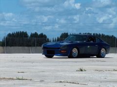
Do you think that you will ever be adjusted that low? I doubt it unless you are using really tall springs. In the spring rates you are going with an 8" spring is the tallest spring that you would want. You can see where my 500# 8" front springs are adjusted to for my ride height in this picture: At that ride height, my oil pan is less than 3" off the ground.
-
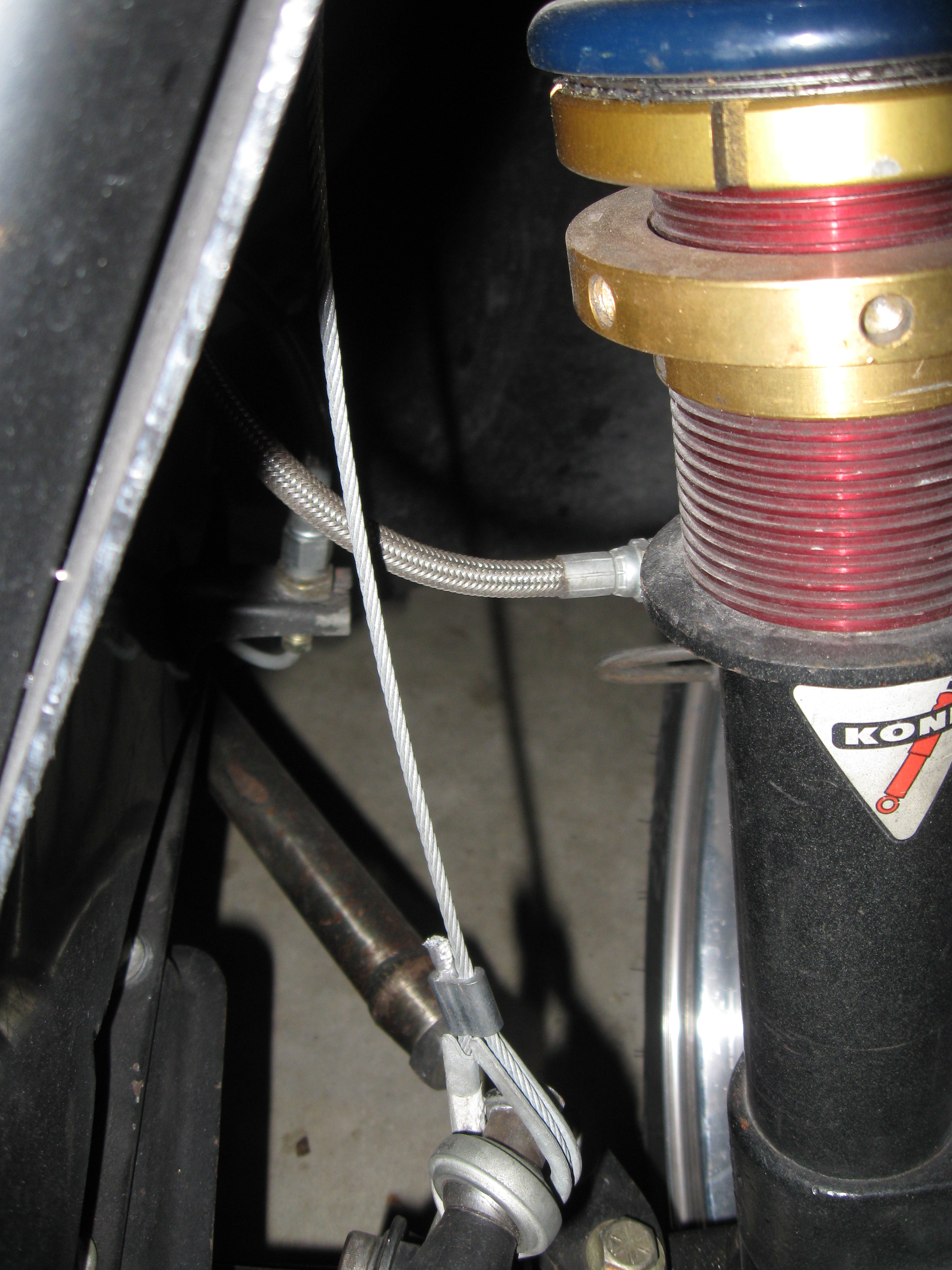
My front suspension is droop limited using cables, but only to the point that the front springs are at their free length when the cables are taut. To make mine, I attached a 1/4" clevis yoke to the top of the strut tower inboard and forward of the upper spring seat, and connected this clevis to a sway bar end link using a 1/8" cable and thimbles. I've attached some low quality pictures that show the set-up with the car at ride height (slop in the cable). These cables are not as close as they look to the brake lines. In two years of autocrossing with these cables installed, I have seen no evidence of contact. My rear suspension is droop limited by the strut assemblies (I sectioned them a little more than I should have). I have about two inches of droop travel in the rear from nominal ride height.
-
Front lower control arms and new subframe
74_5.0L_Z replied to zclubhouse's topic in Brakes, Wheels, Suspension and Chassis
I think you have too many degrees of freedom in your lower control arm / TC rod. The rod end at the junction between the control arm and TC rod needs to be a solid end and not a spherical bearing. Otherwise, the effective length of your TC rod will change as the control arm rotates about its long axis. Oops, BJhines beat me to it... -
Here is an older picture (old engine and no paint) of the car in which you can just see the mid-plate: The mid-plate sandwiches between the block and bellhousing. The mid-plate is 0.090" steel and mounts to two brackets welded to the frame ~1" forward of the firewall.
-
I use a front plate and mid-plate to mount the engine in my car. It works great, frees up a ton of room under the engine, and makes the engine a structural part of the car. The set-up does transmit some mechanical noise, but it is not a bad as I would have thought.
-
Brake help.. Pics included.
74_5.0L_Z replied to abes's topic in Brakes, Wheels, Suspension and Chassis
Are these race pads? Race pads don't work very well until you have a bunch of heat in them. On the street, you will probably never get them up to operating temperature. I use the hawk HP plus pads on my car which does mostly autocross. My pads have to work while cold or moderately hot, and I have been happy with the Hawk pads. They do generate some dust and wear the rotors noticably though. Your rear inside pads are obviously not wearing correctly. Is the outer edge of the pad contacting the structure of the caliper? Is the caliper slider perpendicular to the rotor surface? -
Where are people mounting ECUs in S30s (not 280Zs)
74_5.0L_Z replied to z-ya's topic in S30 Series - 240z, 260z, 280z
My Ford EEC-IV ECU is install in the glove box of my 260Z. I cut a rectangular hole in the back of the glove box that fits the 60 pin connector. -
Having the rear pivot of the T/C rod slightly above the inner pivot of the lower control arm is a good thing. It provides a small amount of increased anti-dive (assuming the outer ball joint is lower than the inner pivot), and a little bit of dynamic caster gain during braking. Just be sure that the inner pivot on the lower control arm is a spherical bearing, or you will get some binding. The inner pivot of my lower control arm has been raised my 3/4", and the rear pivot point of the T/C rod has been raised by the same amount. I have been toying with the idea of raising the rear pivot point a little bit.
-
How much tubing to make a roll bar?
74_5.0L_Z replied to heavy85's topic in Brakes, Wheels, Suspension and Chassis
Looks good. When I installed mine I lined it up so that the roll bar was parallel to the line of the quarter window. To do that, I had to remove the "little nubbin" that you referred to below the quarter window. To remove it, I just used a hole saw. Because it is a tight fit, you will have to strategically plan your welds. If you are not careful, you will end up with welds that you can't reach. I planned mine so that the main hoop, diagonal, downtubes, strut support, and the tubes that go from the sides of the main hoop to the strut brace could be completely removed from the car for final welding. The following picture shows all of the rear structure installed in the car but not welded to the car. Basically everything in this picture was completely welded together before final installation into the car. I could tip it forward and wrap it out through the passenger side door. Once everything making up the rear structure was completely welded, it was put in place and welded to the car as shown in the second picture. Actually, to complicate things further, I also had the door bars to contend with. So the rear structure was put in place but not welded to the car, then the door bars were placed and partially welded to the main hoop. Then the entire structure was shifted forward to gain access to the remainder of the door bar welds, then finally everything was put in place and welded to the floor and strut towers. This stuff takes careful planning. -
After doing about two minutes of web research, I came up with the following: The GT40 heads have a nominal combustion chamber size of 64cc and the early 302 have a nominal combustion chamber size of 58.2 cc. So the downside would be that you would lose compression ratio. The upside is that you would get bigger valves and better flowing ports. Why not go to an aftermarket aluminum head? They are available with small (58cc) combustion chambers and even better flow rates. Currently, I am using the Edelbrock P/N 60379 aluminum heads on mine. They are great heads for a stock bottom end. They were worth 10 mph in the quarter mile over the stock heads. Recently, I upgraded my bottom end to a stroker, so I plan to remove the Edelbrock heads sometime in the future and go with either an AFR185 or the new Ford Z302 head.
-
I bought some GT-40 heads for my father-in-law's 1968 302 that we put in his 1964 comet convertible. The heads were a straight bolt on. The later model heads utilize a pedestal mount rocker arm, while the older heads use the rail type rocker arms. The newer rocker arm design is much better, but you need to be particlular about which push rods you use. For his application (hydraulic flat tappet cam) we ended up using push rods for a 1982 Mustang. The 1982 Mustang had a hydraulic flat tappet cam and the new style rocker arms. If you are going to use aftermarket rocker arms, then ignore the above, but be sure to get the proper length push rods.
-
How much tubing to make a roll bar?
74_5.0L_Z replied to heavy85's topic in Brakes, Wheels, Suspension and Chassis
I had my roll bar bent by the guys at ChassisShop where I bought the tubing. They bent it using a die with a 7.0" centerline radius. I asked them about their bending equipment before I generated the drawing. The as received bar was an almost exact match to the drawing. They charged me $80.00 to do the bending, but the quality of the work was worth it. -
How much tubing to make a roll bar?
74_5.0L_Z replied to heavy85's topic in Brakes, Wheels, Suspension and Chassis
Cameron, The dimensions on my roll bar gives a VERY tight fit. If the guy bending your bar makes an error tell him to make it on the narrow side. If the bar is any wider than my dimensions, it will not fit. Here is the fit in my car: -
How much tubing to make a roll bar?
74_5.0L_Z replied to heavy85's topic in Brakes, Wheels, Suspension and Chassis
Here are the dimensions that I used to construct my main hoop. I believe that the leg length dimensions are a little long (so you will need to trim to fit). A few members have already built roll bars based on these dimensions. I have gotten feedback that the fit was good. http://album.hybridz.org/showphoto.php?photo=2004&ppuser=7833 -
You don't want a 9" deep sump. If you lower the car, the factory 7.5" deep sump gets pretty close to the ground. I had Kevco racing make me a 6.5" deep front sump pan with dual kickouts, racing gates, and a matching oil pump pickup for about $200.00. I now have 7 quart capacity, better oil control, and an extra inch of ground clearance. The guys at Kevco were great to work with.
-
OK. So, if you were looking for the lightest, smallest, best flowing muffler that would satisfy scca noise restrictions, what would you use?
-
This is related I swear: I currently have dual flowmaster 2 chamber mufflers (2.5" in/out). I've been running them for about ten years. The car sounds good and is not overly loud, however with recent engine modifications I feel that the exhaust system is holding me back. The flowmasters are known to be restrictive and this pair was not very well installed. So, I am starting to upgrade the exhaust starting at the back. I am cutting the two crush bent 90 degree bends and the two Flowmaster mufflers off the car and replacing them with mandrel bent 90s and probably a pair of Borla XR-1 mufflers. The main use of this car is autocross, so I am concerned that the Borla XR-1 mufflers may be too loud. I know johnc has experience with these, so I am interested in his opinion. Here are the engine specs: 327 ford stroker 10.5:1 compression 348 rwhp (I expect more after the exhaust modification) I like the Borlas because they are light, compact, and free flowing, but will the Borlas be too loud?
-
Crashed into a wall lastnight
74_5.0L_Z replied to COmputoman's topic in S30 Series - 240z, 260z, 280z
That is how my car looked when I decided to cut the front off and build a tube chassis. It definitely takes a lot of time, effort and skill. If the car is as nice as it looks, the chassis should be sold cheap to someone who wants to undertake the project. It would be a shame to let it get crushed. -
Front to rear weight ratio info wanted for 5.0
74_5.0L_Z replied to waddiejohn's topic in Ford V8Z Tech Board
Yes, the front frame rails were my reference. The angle that I used was kind of arbitrary. It just worked out that installing the engine at that angle provided the best clearance (at the time the car was originally built). I had to adjust the angle of the differential to match. -
Front to rear weight ratio info wanted for 5.0
74_5.0L_Z replied to waddiejohn's topic in Ford V8Z Tech Board
If you are starting from scratch, here are two things that I would do differently: 1. Install the engine offset slightly to the passenger (right)side. My engine is centered left to right. This will help even out the left/right balance of the car and reduce the driveshaft angle (the nose of the differential is offset to the right). 2. Move the front crossmember forward ~1". This allows the sump of the oilpan to drop easily behind the crossmember and provides a significant caster increase. You can only really do this if you have camber plates installed. I would keep the front to rear and up and down position the same as I already have it. The driver's side head is 1" from the firewall, and the centerline of the crankshaft is even with the top of the front frame rails (at the front of the engine). Also the engine is installed at an angle of 2.5* (transmission tail lower than the nose of the crankshaft). -
Front to rear weight ratio info wanted for 5.0
74_5.0L_Z replied to waddiejohn's topic in Ford V8Z Tech Board
Here is a link where I discuss the weight distribution of my car and how it has changed with various modifications. http://forums.hybridz.org/showthread.php?t=92703&highlight=corner+weights -
If you search this forum the Ford driveshaft has been discussed several times. A couple of discussions included me. Here is a good link: http://forums.hybridz.org/showthread.php?t=75715&highlight=neapco
-
First impression of Formula Atlantic slicks
74_5.0L_Z replied to 74_5.0L_Z's topic in Brakes, Wheels, Suspension and Chassis
Just thought I would add my impressions of the FA slicks at the end of their useful life. When I first installed these I was impressed with their overall grip, but thought the slip angle would take some getting used to. Well, as the tires aged, the slip angles kept growing and the traction kept diminishing. This can be expected with any race tire as it ages. However, these tires go away quickly. All totalled, I got about 20 good runs, 20 mediocre runs, and about 10 runs that were scary as hell because I had no traction. For the price that I paid, I guess they worked well enough (I only paid $100.00 for a set of four). Next season, I will fork out the money for a new set of Hoosier A6 275/35/15 tires. The FA slicks are not in the same league as the Hoosier A6 tires for autocross. -
-
Wheel track measurement with Subtle Z
74_5.0L_Z replied to AkumaNoZeta's topic in Brakes, Wheels, Suspension and Chassis
As Dan Juday stated, "there are sevaral factor to consider" when designing the front track width for use with the SubtleZ front fenders. On mine, the front track is 66". I am using the FA slicks which are very short (22.9") mounted on 15x10 wheels. I posted pictures elsewhere to show how they fit and looked on the car. I'll post a few more here: At 66", it looks like I have a little bit of clearance at the front tires, but you need a little wiggle room to allow for suspension motion while the wheels are turned.