
74_5.0L_Z
-
Posts
1194 -
Joined
-
Last visited
-
Days Won
30
Content Type
Profiles
Forums
Blogs
Events
Gallery
Downloads
Store
Everything posted by 74_5.0L_Z
-

Stock control arm length?
74_5.0L_Z replied to olie05's topic in Brakes, Wheels, Suspension and Chassis
I had a ball joint that was worn, so I cut it apart while I was trying to locate my roll centers. I found that the center of the ball is approximately located along the upper surface of the webbing for the four bolt flange where it meets the spherical housing of the ball joint (right where the webbing blends into the housing). This will get you within ~1/16". To be a little more clear, I mean the most outboard point where the webbing meets the housing. -
Stock control arm length?
74_5.0L_Z replied to olie05's topic in Brakes, Wheels, Suspension and Chassis
The center to center length for the front control arms (using a tape measure) is 11.25". The rear control arms are 14.5 center to center. Be careful about the factory frame drawings. The 240Z and 260Z factory manuals had some errors. I believe the errors were corrected in the 280Z drawing. -
Jon, Go to the following link: http://www.fromsteve.net/carstuff/suspension/SuspensionCalc.htm After the page opens, select the Sway Bar Rate Calculator tab at the bottom of the page. On that page is a figure of a sway bar with dimensions A, B, C, and D. Would you measure those dimensions for me on your sway bar and post them here? Ignore the extra bend in the sway bar. The extra bend in the Z sway bar provides clearance for the L6 oil pump and really only has a small affect on the stiffness. Dan
-
I experimented with my front sway bar today. The purpose of the experiment was to quantify effective spring rate of the sway bar at the outside wheel. Here are the specifics of my front sway bar: Modified suspension techniques 25 mm front sway bar: The lever arms have been shortened and fitted with rod ends. The measured dimension of the bar are as follows: A = 7" ---------Length of lever arm measured perpendicular to B B = 30.5 " --------Length of bar in torsion C = 7.75" -------Length of lever arm (along arm) D = 1.005"-------Diameter of sway bar Sway bar installation ratio 0.58 Fred Puhn gives the following formula for the stiffness of a sway bar on page 150 of his book, "How to make your car handle." K = (500,000 x D^4) / (0.4244 x A^2 x B + 0.2264 x C ^3) For the dimensions of my bar, the theoretical stiffness given by Puhn's formula would be as follows: K = (500,000 x 1.005" ^4) / (0.4244 x 7" ^2 x 30.5" + 0.2264 x 7.75" ^3) = 689.6 lbf / in This measurement gives the stiffness of the sway bar for one inch of deflection at one sway bar end. To find the stiffness for one inch of deflection at the wheel, you multiply the stiffness by the square of the sway bar installation ratio. So for my car, the theoretical sway bar stiffness for one wheel rising 1 inch with the other wheel locked in place should be 698.6 lbf/in x 0.58^2 *1 inch= 231 lbf Formulas are great, but their results need to be verified, so here is what I did: Removed both front springs. Replaced the drivers side spring by a 7" x 2.5" x 0.125 wall aluminum tube. Reconnected both struts (one with no spring and one with the aluminum tube to lock that side at ride height). Disconnected the sway bar. Placed a bathroom scale (analog type) under the passenger side front hub with a scissor jack, and raised the hub (with out spring or sway bar) to ride height. Record weight of hub, and scissor jack. (67 lbs) Connected sway bar. Raise hub using scissor jack until hub rises 1 " above starting position. Record weight of hub + scissor jack + force of sway bar. (275 lbs) Subtract initial measurement (hub + jack) from final measurement (hub + jack + force of sway bar) to get the force at the hub caused by 1 " of wheel motion. Here are the results: 275 lbs (hub + jack + force of sway bar) 67 lbs (hub + jack ) ______ 208 lbs (measured sway bar force at hub for a single wheel deflection of 1 ") This is slightly less than the force predicted by Puhn's formula. The error is (231 - 208)/231 = 10.3 %. In all fairness to Mr. Puhn, much of that error can be accounted for by the inaccuracies of my own measurements.
-
I was poking fun at the picture. I was not criticizing. I'm quite sure that my situation looked just as comical to innocent bystanders.
-
I'm sorry, but that looks like it should be included as a workplace safety message. I sure my job would have been included on the same page.
-
After I finished the tube front end on mine, I needed to prep and paint the bottom of the car (from the rear crossmember forward). The front suspension was removed and there was no drivetrain or interior. The rear suspension was installed, so I grabbed the two front frame rails and rolled the car out of the garage like a big wheel barrow. Once in the driveway, I blocked the rear tires and stood the car up until the rear valance was almost on the ground. I secured it in this position with a rope up to a tree limb above. I was then easily able to scrape, clean and paint the underside of the car.
-
I switched to Hypercoil springs because I have heard that they have less variation in spring rate than some of the others. But yes, if I ever get truly serious, I would need to measure the rate and free length of every spring (and recheck periodically). In the meantime, I'll get as close as I can using off the shelf spring rates and movement of weight. The deeper you look, the deeper it gets.
-
I will try to measure the bar. A simple experiment is worth a thousand calculations as long as all the variable are covered. How long are your lever arms on your sway bar? Were your bearings located near the stock location near the bend in the bar? How flexible is the workbench that it was bolted to? Were you measuring the deflection at a point equal to the end of the lever arm, or were you measuring the deflection at the end of a longer lever?
-
I dug out my statics text and went through the torsion calculations and if I assume infinitely stiff lever arms, I get pretty close to what the WTW calculates for a 1" sway bar. The WTW comes up with 659 lb/ in (That's one inch on each side), and I came up with 592 lb/in (Again one inch on each side). I do plan to measure the rate, but I am pretty darn sure that it will measure greater than 120 lb/in. Is it possible that you annealed your bar by welding on it? I have seen suggestions that sway bars that have been welded need to be heat treated.
-
I already had my 1" sway bar in place and haven't had time to measure it's rate or install the sway bar that my calculations say should work (stock 0.71" sway bay modified for rod ends and 7.5" lever arms). I ran the car with the 450 lb/in rear and 425 lb/in front with the 1" sway bar. The weight transfer worksheet gave me a magic number of 9.4% which predicts understeer (which it did). With the new sway bar and swapping the springs front to rear, the weight transfer worksheet gives me a magic number of 3.2% which is much closer to neutral. My calculations for the sway bar rate agree pretty closely with what the weight transfer worksheet predicts. John, I plan not to miss any more seat time regardless of the springs that I have installed. My next event is one month from now. By then, I will have the new sway bar set-up in place and hopefully the new springs. I'll wait till I get the new springs in place before I get it balanced. Oh, my weights are with me in the car and a full load of fuel.
-
I ran an autocross yesterday with my new set-up (sort of). I had all of the new springs and struts in place, but I haven't had the opportunity to re-corner balance the car or get it aligned. Additionally, my front sway bar is much too large for the springs that I have chosen (I was pushing a bit). Nevertheless, the car did pretty well. I took first in E-mod against 4 other cars in my class. I will say that the new set-up will take some getting used to. The car reacts much quicker with a 2.5 Hz suspension frequency than with a 1.8 Hz frequency. I think that I will like it as I get accustomed. As I was inspecting the car today, however, a strange and troubling thought occurred to me: These cars are not symmetric left to right. The left side is heavier than the right side. Yet, the spring that I put in the left front is the same rate as the spring that I put in the right front. The left front sprung weight is 586.6 lbs and the right front sprung weight is 543.6 lbs. The resulting frequencies for the left front and right front are 2.28 and 2.37 respectively. The resulting frequencies for the left rear and right rear are 2.20 and 2.28 respectively. So, what does all this mean? It means that in order to have the suspension frequencies match left to right, the car needs four different rate springs. For mine, I would use the existing 450 lb/in spring on the left front, and use a 410 lb/in right front spring. On the rear, I would use the 425 lb/in spring on the left and need a 390 lb/in spring on the right rear. By doing all of this, the car should sit level when corner balanced and transfer weight forward and backward equally between the left and right tires during acceleration/braking. Please someone tell me that I am full of crap. Otherwise, I will be ordering two more springs.
-
One other possibility has occurred to me. If your timing is retarded (at idle) so that you get spark at a few degree after TDC instead of ~12 before TDC, you will get a situation like you've been describing. My father in-law's 1964 comet was having similar issues to those you are having with yours, and setting the timing correctly cured it.
-
An easy way to test for a bad or mis-installed thermostat is to remove it. Run the car with the water neck reinstalled (sans thermostat) and see if the problem goes away.
-
I think you have the thermostat in upside down.
-
Congratulations John. I look forward to checking out your car in the magazine.
-
Name: Dan McGrath Handle: 74_5.0L_Z City/State: Rockledge, FL Year/Model: 1974 260Z Vehicle Details (max 20 words): 5.0L Ford/T5, Tube chassis, custom GT-40 style hood and air dam Vehicle Picture:
-
I worked through Cary's spreadsheet and also though all of the calculations in chapter 16 of RCVD and worked out my new spring rates to go with the new struts. I ordered my new springs yesterday. In the rear, I plan to run 8" 450 lb/in springs and no sway bar. In the front, I plan to run 8" 425 lb/in springs and a 7/8" sway bar. This set-up combined with the weight distrubution, roll centers, unsprung weight, motion ratios, and such should result in a front load transfer that is about 5% higher than my front weight distribution. My resulting undamped natural frequencies will be 2.39 Hz for the front suspension and 2.44 Hz for the rear. Looking at the koni 8610 graphs, the 8610-1149 shocks will work well with these spring rates in the mid range of their adjustment, and the 8610-1437race struts will work well with these spring rates on the low end of their range of adjustment. I am working on the assumption that a damping ratio of ~0.7 is desirable in the 0 to 4 in/sec range of damper shaft velocity. In addition, I discovered an interesting thing while comparing the 8610-1437 to the 8610-1149: The 1437 has a longer stroke than the 1149, but the 1149 has a longer overall extended length. I discovered this because I was trying to regain some droop travel in the rear. By moving the 1437 from the rear to the front and the 1149 to the rear, I was able to regain 3/4" of droop travel in the rear. Moral of the story: I would only section the rear struts by 1.5" if you are using the 8610-1437race strut. The strut housing can be sectioned more for the 1149 insert.
-
Add me to the list of people that got smacked up side of the head by their drill while cutting notches. Also be aware that the metal around the newly completed notch will be razor sharp and very hot. I'm sure no one needs to tell you to wear eye protection.
-
I haven't forgotten you. In fact you got me thinking (damn you). My current sway bar is a 1" attached to the lower control arm at approximately the stock location. The installation ratio at the stock point will be pretty low because it is well inboard of the ball joint. But, if you flip the rod end over and attach it to the strut, the motion ration will be pretty close to the strut installation ratio. What this means is that I will be able to use a much thinner (lighter) sway bar and still get the same amount of roll resistance. That is one of the things that I am still working on. I'll post the results.
-
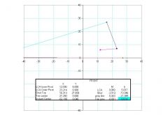
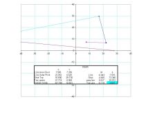
Another busy weekend: I did the following: 1. Determined my roll centers. 2. Re-measured the motion ratios 3. Played around with Smithee's Weight Transfer Worksheet using the data that I know about my car. First, I'll detail the procedure that I used to determine my roll centers. The process required measuring the following: - Front and rear track (center to center) -lengths of front and rear control arms (center to center) ---14.5" rear and 11.25" front. -spacing between the left and right LCA pivot points -height of front and rear LCA pivot points from ground. -spacing between left and right pivots for the tops of the struts (center of spherical bearing). -heights of front and rear strut top pivot points above ground. I performed the whole process twice on the front suspension (once with no bump steer spacer and once with a 1" spacer). My results were that my rear roll center is 3" above ground and my front roll center is 2 " below ground (with no spacer). The front roll center rises to ground level (0.014") when I installed the 1" spacer. Here are screen shots showing the excel graph of the front and rear data: I reperformed the motion ratio measurement (just to be sure). This time I did the front at the hub center like last time and I also redid it at the tire centerline. The hub centerline and tire centerline data agreed with each other, but both were slightly different than last time (I think I was a little more careful this time). Additionally, I decided to install the bump steer spacer and see if there was any change in the motion ratio. The results from all of this is as follows: Front: --Hub center and tire patch center (no spacer) Installation ratio = 0.915 --Hub center with 1" bump steer spacer installed Installation ratio = 0.8911. Rear: --Hub center installation ratio = 0.901 What can probably be discerned from the variation in my results is that the error in my measurements doesn't justify my reporting more than two significant figures. So we'll just say that the rear motion ratio is 0.90 and the front motion ratio is 0.91. So, where does this information get me? Hopefully, it gets me closer to picking some new spring rates. Toward that end I plugged all of my data into Smithee's Weight Transfer Worksheet and found some possible spring combinations. I'll write up the details of that later, but I believe that I am going to end up with 350 lb/in rear springs and 375 lb/in front.
-
-
-
74_5.0L_Z shamelessly emulates Terry Oxendales Hood
74_5.0L_Z replied to 74_5.0L_Z's topic in Body Kits & Paint
I've posted completed pictures of the car elsewhere, but for closure of this thread I'll post them here too. The first three were taken at the National Z car convention in Daytona. The next were taken at an Autocross two weeks ago. -
Here is what I used: http://www.pro-tools.com/hsn500.htm Great tool. I cut literally hundreds of notches. As stated earlier: Use a good bi-metal hole saw. Go slow Use plenty of cutting fluid.