
74_5.0L_Z
-
Posts
1194 -
Joined
-
Last visited
-
Days Won
30
Content Type
Profiles
Forums
Blogs
Events
Gallery
Downloads
Store
Everything posted by 74_5.0L_Z
-
 A little update: I ended up replacing my tires with the same size (245/45/16) Hoosier A6. I wanted to go up a size, but my old tires became corded before I could acquire some larger wheels. Even though I couldn't go to the next larger size, I have to say this: New Hoosiers are MAGIC! My old tires had died from age and heat cycling, so I had enough time to forget what they should feel like. The car does what I tell it to, when I tell it to almost without exception. I just wish the driver was a little better. Additionally, I have installed the front droop limiters. They are simply cables that prevent the strut from drooping past the point where the spring comes loose. In my case they stop about 1" of droop travel. I have not installed them on the rear because my rear springs do not unload at full droop. The front droop limiters do reduce body roll. Here is some video of the car from an autocross at sebring two weeks ago: I am extremely happy with the way the car is handling, but I still plan to get some bigger wheels before the next set of tires.
 -
Chassis Setup (corner weights)
74_5.0L_Z replied to 74_5.0L_Z's topic in Brakes, Wheels, Suspension and Chassis
I checked my numbers with DG's calculator and came up with LF = 665.31 Lb RF = 621.69 Lb LR = 707.69 Lb RR = 661.31 Lb. These are pretty darn close to my final numbers of LF = 662 Lb RF = 623 Lb LR = 708 Lb RR = 661 Lb. -
Chassis Setup (corner weights)
74_5.0L_Z replied to 74_5.0L_Z's topic in Brakes, Wheels, Suspension and Chassis
I corner balanced the car again yesterday. I try to do this whenever I make significant changes. For those of you following along, I completely changed my suspension set-up. I went from 250 rear/ 200 front springs with a 1" front sway bar to 425 rear/450 front springs and an 18 mm front sway bar. The car has also been lowered 1" all around, the stock seats have been replaced with lightweight MOMO Start2007 seats, the rear struts have been sectioned, and rear camber plates installed (all since October). So I thought it was time to rebalance the car. Here are the starting numbers with driver (me) and fuel: LF = 683 Lb RF = 604 Lb LR = 690 Lb RR = 679 Lb. Total = 2656 Lb These were my percentages: (LF + RF)/ Total = (683 + 604)/2656 X 100%= 48.5 percent on the front 51.5 % on the rear. (RF + RR)/ Total = (604 + 679)/2656 X 100% = 51.7 % on left and 48.3% on right. my diagonals were a little off: (LF + RR) = (683 + 679)= 1362 (RF + LR) = (604 +690) = 1294. To fix this, I raised the RF spring perch 1 turn (1/8"), and the LR 1 turn. After this minor adjustment, these were the results: LF = 662 Lb RF = 623 Lb LR = 708 Lb RR = 661 Lb. (LF + RR) = (662 + 661)= 1323 (RF + LR) = (708 +623) = 1331:mrgreen: Here is the thread that discusses all of the suspension stuff that has been performed since October: http://forums.hybridz.org/showthread.php?t=130005 Here are the final numbers with fuel but no driver: LF = 603 Lb RF = 622 Lb LR = 627 Lb RR = 617 Lb. Total = 2469 Lb These were my percentages: (LF + RF)/ Total = (603 + 622)/2469 X 100%= 49.6 percent on the front 50.4 % on the rear. (LF + LR)/ Total = (622 + 617)/2469 X 100% = 49.8 % on left and 50.2% on right. -
Home Made Control Arms
74_5.0L_Z replied to EMWHYR0HEN's topic in Brakes, Wheels, Suspension and Chassis
Those look great! When I get around to making my next set, they will be similarly constructed. The only thing that I plan to do differently is make the rear heim the solid point, and let the front heim be the toe adjuster. What wall tubing did you end up with? My current control arms are made using 1.125 x 0.058 4130 tubing, but they use a lot of extra triangulation for redundancy. With your new control arms you have converted the rear suspension from an H-arm to an A-arm toe link type strut. By doing so, you have given youself more freedom regarding toe and caster. The H-arm type strut suspension demands that the strut is perpendicular to the control arm. If the strut isn't perpendicular, the control arm and strut must flex or bind as the suspension goes through its range of motion. Because of the requirement for an H-arm strut to be always perpendicular to the control arm, caster and toe are limited. The A-arm type gives you more options. You can now move the top of the strut forward or aft. As the suspension moves through its range of motion, the toe link rotate to prevent the suspension from binding. Moving the top of the strut forward or aft will allow you to play with anti-squat and roll steer of the rear suspension. -
Anyone know what kind of ouside rear view mirror this is?
74_5.0L_Z replied to BurnoutZ's topic in Body Kits & Paint
I think they may be second generation RX7 mirrors. I have been thinking about putting a set on my car. -
-
-
Home Made Control Arms
74_5.0L_Z replied to EMWHYR0HEN's topic in Brakes, Wheels, Suspension and Chassis
What Jon said... I made my control arms several years before the threads mentioned above. My control arms are functional and light, but I have to be careful to verify that the bolt going through the outer pivot is not in a bind after a camber or toe adjustment. If I were to make another set, they would be a little different and would incorporate what has been learned during discussion on HybridZ. My new set would look more like Cary's (tube80z). The only thing that I might do different is make the rear rod end fixed in the plane of the control arm and let the front rod end be the toe link. Either way, I can reuse my jig (as can you) with little or no modification. -
Home Made Control Arms
74_5.0L_Z replied to EMWHYR0HEN's topic in Brakes, Wheels, Suspension and Chassis
That is similar to the manner in which I constructed my control arms. Here is a Jig that I made: On my jig, you weld one side of the control arm, then flip the control arm to the other side and then weld the other. One issue that I see with your control arm design is that the axis of the two rod ends are not parallel. As you adjust the length of the rear rod end, the spacing between the rod ends will change. This will create a binding situation between the strut and control arm. -
The stock seats are fairly light as stock seats go. In my case however, I autocross the car. I count every pound, and I needed lateral support. I am at the point with my car that finding weight that can easily be removed is difficult. So losing 18 pounds with a pair of lightweight seats was a bonanza.
-
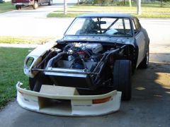
I just put a pair of MOMO Start2007 seats in my car. They are not a cheap seat, but they are relatively inexpensive. They are FIA approved fiberglass seats that weigh 18.5 lbs each. With the mounting brackets installed, they weighed 23.5 lbs each. The stock 260Z seats weigh 32.5 lbs each, so I was able to lose 18 lbs by installing the two seats in my car. I have had the seats in the car for three autocross events, and really like the comfort. They fit me perfectly but will not work for larger drivers. I am 6'0" and weigh 185 lbs. They are a tight fit in the car. The widest part of the seat at the shoulders just barely clears the door, and the widest part at the knees just barely clears the driveshaft tunnel. Because they are side mount seats, it is possible to mount them very low(which is good for me). They seem like they were made for mounting in the Z car. I bought my seats from LTB motorsports here in florida. He is a local SCCA racer and has an Ebay store. For me, the good part was that he was nearby, so that I could sit in them before I bought them. He sells them for 361.00 each on Ebay with free shipping. If you are local and can pick them up, you can save some money. You will also need the MOMO side mount brackets. This is the only picture that shows the seats at all. I'll have to borrow a camera and get some installation pictures.
-
I haven't used the ultra-flo X muffler, but thanks for posting. I currently use a pair of old 40 series Flowmaster mufflers. They sound great, but they are heavy. So I am considering replacing the two flowmasters with a single ultra-flo X (somewhere along the tunnel) with mandrel bent tail pipes to the rear. I think the Ultra-Flo X should provide sufficient sound attenuation without additional mufflers down stream (At least for my application: E mod autocrosser).
-
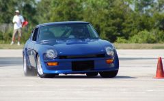
Thanks for the responses. Jon you are correct, I am neglecting the tire contribution to roll. Also, I lowered my tire pressures for this event. I have previously been running 40 psi front and 36 rear (cold), for this event I lowered the front to 32 and the rear to 28. I am just shooting in the dark until I get a tire pyrometer. That will be my next purchase. Cary, I have been wanting to try droop limiters. My next event is in 2 weeks in Gainesville, Fl (05/18/08). I hope to have droop limiters on the front by that time. From my picture, it appears to me that the inside tires are fully drooped (limited by the struts) and that the outside tires are on the Koni bump rubbers.
-
Saturday, I finally got the car aligned for the first time since redoing my suspension. Here are the alignment settings that I used: Front: 0 toe, -2.5 degrees camber, and 5.6 degrees caster. Rear: 0.10 degrees toe in, -2.1 degrees camber. Sunday, I ran an autocross and the car did extremely well considering that I have some seriously dead Hoosier A3S04 tires. At the limit, the car had just a little understeer, and the rear traction was much improved from the last couple of events. I attribute this to using less rear camber and less toe in at the rear. There was a photographer present, so I asked him to get some pictures of the car in various parts of the track. The following picture surprized the heck out of me. The picture was taken at the end of a fast sweeper with a decreasing radius exit. The body roll in the picture is about 3 degrees. This is more roll than I expected the car to achieve with the tires and suspension that are in place (Hoosier 245/45/16, 450 lb/in front springs and 425 lb/in rear springs). The weight transfer worksheet predicts 1.6 degrees of roll per gee of lateral acceleration (for a steady state 1 gee turn). I guess I overlooked the additional roll that will occur in transient manuevers. Also from the pictures, it looks as if the rear tires have sufficient camber to compensate for body roll, and it looks like the front tires could use a little more negative camber. Unfortunately, in order to get more negative camber on the front I have to either lengthen the lower control arms or give up a little bit of caster. I will probably make some new lower control arms (and outer tie rods) to widen the front track, and allow me to run more static negative camber. Before I do make new control arms, I plan to do the following to add to this thread: Measure front camber gain. Measure front bump/roll steer.
-
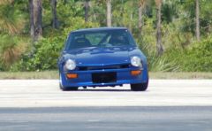 This picture shows the body roll straight on from the front. This was at the end of a fast sweeper with a decreasing radius at the end. The car was definitely near the limit of its lateral acceleration. Measurement of the picture shows about 3 degrees of roll.
 -
-
Which aftermarket caliper?
74_5.0L_Z replied to rudypoochris's topic in Brakes, Wheels, Suspension and Chassis
Like johnc, I am using Outlaw 2800 calipers on all four corners. I've been quite happy with them. -
Thanks Jon, Were you using the bias ply or radials? Bias Ply P/N________Size_______App______TW_____Dia______Circ_____ Rim Width 43361__22.5 x 9.5-15___FA______9.2"_____22.9"_____72.0"_____10" Radial P/N________Size_______App______TW_____Dia______Circ_____ Rim Width 43570__23 x 9.5R-15____FA______9.4"____22.9"_____72.0"_____10" These would both be good options for my car. Regardless of which of these tires that I select, I am going to need some different wheels.
-
Cary, Thanks for the reply. All of those cars look like some serious hardware. I love the big rear quarter panels. Makes me wish that I had flared mine a bit further (but alas). Hoosier lists several FA tires on their web site. These tires range in size from 22.0 x 9.0-13 to 23.5 x 11.0-15 in Bias Ply slick and 23 x 9.5R-13 to 23.5 x 13.0R-15 in radial slicks. The big tires for both are supposed to be mounted on 14" wide wheels:shock:. Are you guys using the Bias ply or radial tires? Because of my brakes, I cannot use the 13" at all, and the available FA 15" sizes are incompatable with my bodywork. With the right selection of backspace, I could fit these Hooiser Bias Ply tires on all four corners of my car. P/N________Size_______App________TW_____Dia______Circ_____ Rim Width 43470__22.0 x 10.0-16__GT2_______ 9.7"___ 22.9"____72.0"_____10" Other options are to use the R6 DOT radial tires from Hoosier. The following could be made to work on my car: P/N________Size________TW_____Dia______Circ_____ Rim Width 46535___P275/35ZR15___10.1"___ 23.0"___ 72.2"______ 9.5" 46630___P275/45ZR16___10.3"___ 25.6"___ 80.5"______ 9.0" 46730___P275/40ZR17___10.3"___ 25.5"___ 80.1"______ 9.5" I have been trying to decide whether to stick with a DOT radial or to try a bias ply slick. Which lasts longer? I am tired of tires that "go away" after only a few events. I love the pictures as a means of troubleshooting the car. I will try and get someone to start getting some pictures of my car at work. You mentioned that one of the crew is using droop limiters. Is he using them on the front and back, or just on the front? I have been toying with droop limiting my front suspension.
-
Me too. No rear bar.
-
Jon, You are probably right. I'm just looking for a good starting point.
-
In my previous post, I stated that my car would roll 1.6 degrees per G and that I had set the static camber to -1.3 degrees. The static setting of -1.3 degrees would give me -1.89 degrees on the outside tire in a 1 G turn. I was happy with myself because I had stood the tire up a little bit more vertical and convinced myself that I would have enough camber at max lateral acceleration. Then Cary (Tube80Z) had to go and inject a little reality: "I should be generating 1.3 to 1.5 gs of lateral acceleration." At 1.5 G my car should roll 2.76 degrees, the outside tires should rise (relative to the body) 1.2", and the inside tire should droop 1.2" from their static ride position. With -1.3 degrees statics camber, I will have about -2.2 degrees of camber in a 1.5 G turn while the body will roll 2.76 degrees. The tires will go 0.5 degrees positive in camber. I want at least enough camber to offset the body roll. I'm looking for the least amount of static camber to improve my forward traction, but I want enough camber to prevent the tire from going positive due to body roll. So, I generated some camber curves for several positions of my camber plates. For each of these positions, the static ride height was held constant (5.75" at rear of the rocker panel, or 7.125" at the center of the LCA inner pivot). On this graph 0 on the X axis represents my static ride height. Displacements to the right represent bump of the tire and while displacements to the left represent droop. Each of the curves represent a different setting of the camber plate. The bottom curve is what I have settled on (for now). I have set the rear tires to have -1.88 of static camber. This will give -2.8 degrees of camber on the ouside wheel and 0.88 degrees on the inside wheel in a 1.5 G turn. If you analyze the graph, you can see that there are two things that affect your camber. First, If you hold your ride height constant, you can increase/ decrease camber by adjusting the camber plate. Second, with the camber plate adjustment held constant, you can increase/ decrease camber by lowering/raising the ride height of the car. If you look at the curves, raising the ride height 1" makes the camber become ~.74 degrees more positive. So as Terry noted: the Ground Control camber plates will be set at or near there maximum outboard position on a severly lowered car. BTW: Cary what wheels / tires are on that car? I'm trying to decide which tires are going on mine next.
-
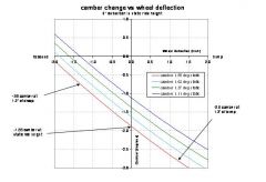 These camber curves are for my rear suspension. The car has GC camber plates and is lowered such that the center of the LCA pivot is 7.125" above ground. The LCA pivots are the aluminum delrin bushing adjusted to give max negative camber.
 -
In going through all of this process, I have installed 425 lb/in rear springs, 450 lb/in front springs, replaced my front 1" sway bar with a modified stock (18 mm) sway bar, and lowered the heck out of my car. The car is about 1.5 " lower than when I started this process and about 3.5" lower than stock with 245/45/16 tires. The car is much better in transitions than it was, but I have been having trouble putting down the power since going to the higher spring rates. I have not aligned of or corner balanced the car since starting this process. Just looking at the car though, it was obvious that the rear tires had acquired a bunch of negative camber. At the old ride height with the 250 lb/in rear springs, I ran -2.0 degrees of rear camber. At the new ride height, I found that I had -3.7 degrees of rear camber. Perhaps this accounts for some of my lost rear forward traction. So, I decided to try and set my rear camber to a more reasonable number. That begs the question: What is a good rear camber setting for my new suspension setup that will optimize forward traction without letting the camber go positive with body roll? To answer that question, I needed to know two things: First, how much will my suspension compress in roll? Second, how much camber gain will my rear suspension give me per inch of wheel travel? To answer the first question, I did the suspension analysis as outlined in RCVD and as implemented in the weight transfer worksheet. The weight transfer worksheet predicts 1.6 degrees of roll per G of lateral acceleration. To answer the second question, I spent today measuring camber curves for various positions of my rear camber plates. What I ended up with was setting the plates as far towards positive camber as the slots would allow. This yielded -1.3 degrees of camber at static ride height. The camber gain at this position is -0.74 degree/ inch in the range centered around my static ride height (The camber curve is not really linear, but can be approximated as linear over small ranges). If we assume that the suspension rolls about the center (big assumption), that amount of roll corresponds to approximately 0.8" of bump on the outside wheels and 0.8" of rebound on the inside wheels. If we also assume that we want the tire vertical at 1 G lateral acceleration, then we choose a static camber that will yield -1.6 degrees at 0.8" of bump. For my case, the most positive that I was able to set my camber was -1.3 degrees at static ride height. At 0.8" of bump (1.6 degrees of roll), the camber should be -1.3 deg - (0.74 deg/in x 0.8 in) = -1.89 degrees. This value is more than the 1.6 degrees of body roll, so I should have a little camber more than the minimum required to keep the outside tire from going positive. I'm sure that I have oversimplified some of this, but I am quite sure that the car will be a bit happier than it was with -3.7 degrees of static rear camber.
-
I've been using black aluminum pop rivets from these guys: http://www.colemanracing.com/catalog/product_info.php?products_id=3181 They are $21.59 for 100 rivets. They look exactly like the factory plastic rivets. The down side is that removing them requires that they be drilled out.