74_5.0L_Z
-
Posts
1209 -
Joined
-
Last visited
-
Days Won
34
Content Type
Profiles
Forums
Blogs
Events
Gallery
Downloads
Store
Everything posted by 74_5.0L_Z
-
So, where are you acquiring these 3D engine models? I would love to get a decent 3D model of the old 87 - 93 5.0L Ford engine.
-

Front Suspension Kinematics
74_5.0L_Z replied to 74_5.0L_Z's topic in Brakes, Wheels, Suspension and Chassis
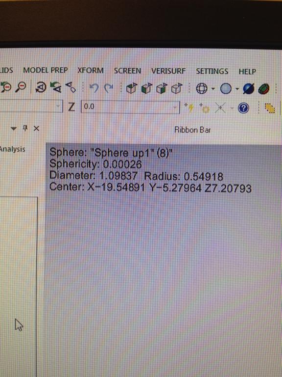
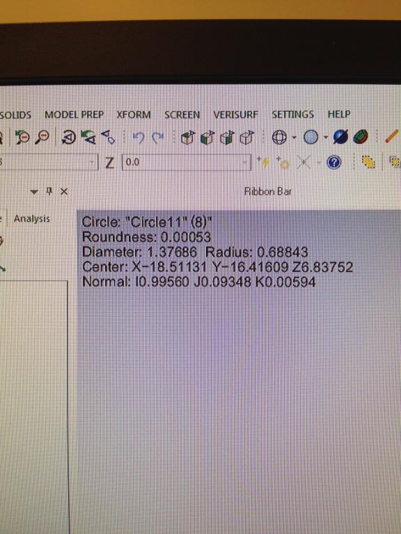
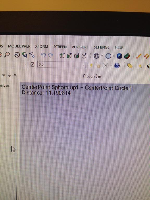
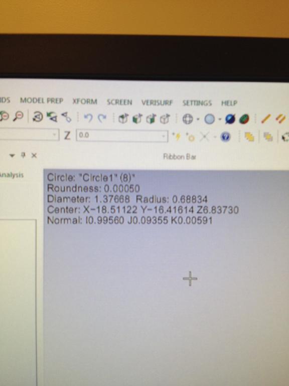
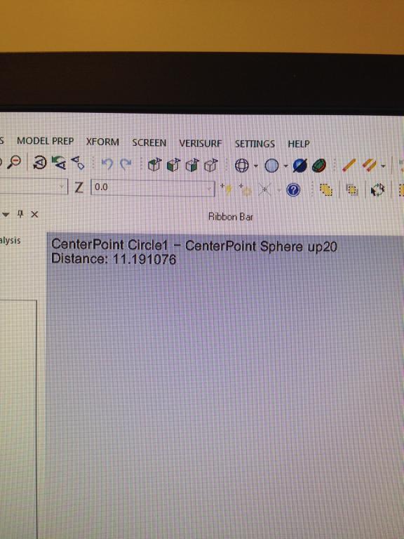
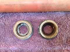
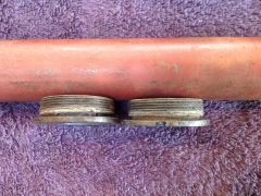
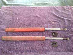
One of fellow members here (erikr) really stepped up and has helped with improving our dimensional knowledge of the S30 front suspension. He measured two 240 Lower Control arms using a coordinate measurement arm. Attached are photos of the set-up and the results. We can say with great certainty now that the center to center distance of the LCA is 11.2 inches I would like Erik to describe the process. Also, I invite others to help us out.
-
From the album: Parts For Sale
Koni 8641-1032 -
Parts For Sale
-
-
From the album: Parts For Sale
Koni 8641-1032 -
From the album: Parts For Sale
Koni 8641-1032 -
From the album: Parts For Sale
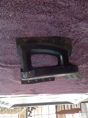
1974 260Z Battery Tray -
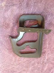
From the album: Parts For Sale
1974 260Z Battery Tray -
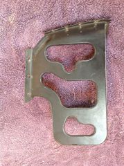
From the album: Parts For Sale
1974 260Z Battery Tray -
Eibach 10 inch 250 lb/in 2.50 diameter coilover springs
74_5.0L_Z posted a gallery image in Members Albums
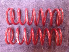
From the album: Parts For Sale
Eibach 10 inch 250 lb/in 2.50 diameter coilover springs -
From the album: Parts For Sale
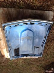
1977 280Z hood -
From the album: Parts For Sale
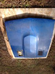
1977 280Z hood -
From the album: Parts For Sale
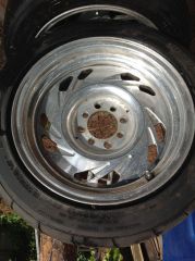
15x8 Centerline Scorpion -
From the album: Parts For Sale
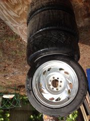
15x8 Centerline Scorpion 1 -
From the album: Parts For Sale
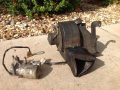
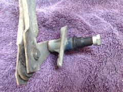
1971 240Z blower and wiper motor -
From the album: Parts For Sale
260Z Bumper Parts -
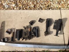
From the album: Parts For Sale
260Z Bumper Parts -
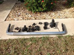
From the album: Parts For Sale
260Z Bumper Parts -
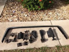
From the album: Parts For Sale
260Z Bumper Parts -
From the album: Parts For Sale
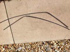
260Z Drip Edge Chrome -
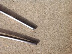
From the album: Parts For Sale
260Z Drip Edge Chrome -
From the album: Parts For Sale
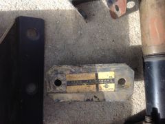
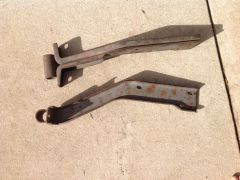
240Z Front Bumper Mounts -
From the album: Parts For Sale
260Z Wiper parts -
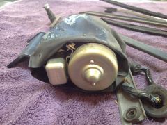
From the album: Parts For Sale
260Z Wiper parts -
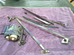
From the album: Parts For Sale
260Z Wiper parts