74_5.0L_Z
-
Posts
1194 -
Joined
-
Last visited
-
Days Won
30
Content Type
Profiles
Forums
Blogs
Events
Gallery
Downloads
Store
Everything posted by 74_5.0L_Z
-
I have the Subtle Z kit (modified) on my car and I have plenty of space for 275/35-15 Hoosier A6 and Avon 23x10.5-15 Tires on 15x10 wheels with 5.25 inch backspace.

-
Just an aside: The Ford engine family that included 221, 260, 289, 302 (5.0L), and 351W all have 90 degree angles between their banks. It would be more appropriate and correct to refer to these as Windsor engines and not 60 degree engines.
-
Mike, Midwest Control sells adjusters like the ones that you made: http://www.midwestcontrol.com/series.php?id=194
-

First impression of Formula Atlantic slicks
74_5.0L_Z replied to 74_5.0L_Z's topic in Brakes, Wheels, Suspension and Chassis
Caster has some really good benefits on our cars and also causes some problems. First the good: With our front struts we have a large Steering Axis inclination (SAI). With factory settings, the cars have very little caster. So, with the factory settings the outside front wheel first tends slightly toward negative camber when the wheels are barely turned and then swings toward positive camber as the wheel is turned further. Similarly, the inside wheel will slightly gain positive camber as the wheel is turned. Ideally, the outside wheel would gain a lot of negative camber and the inside wheel would gain a lot of positive camber as the wheel is turned. Adding caster helps the camber gain a bunch. On my car I have 6.4 degrees of caster and -1.8 degrees of static camber. When I steer the front wheels 5.7 degrees, my outside front wheel gain negative camber so that it has -2.35 degrees, and the inside front wheel gains positive camber to -1.1 degrees. This change in caster is before the outside wheel compresses and the outside wheel droops. The changes in caster from strut compression / extension will add to that from turning. The change gets really significant for tight turns. If I steer my front wheels by 30 degrees(essentially full lock) the outside wheel goes to -2.9 degrees camber and the inside wheel goes to +3.9 degrees of camber. It has been shown that having caster about half of the SAI give pretty good caster gains with turn of the wheels. So, for our cars 6-7 degrees is the rule of thumb. Now the bad: Adding a bunch of caster causes problems. First, it causes the weight jacking / de-wedging problem that I talked about earlier. The combination of caster and SAI combine to cause the front spindle to swing on an arc. Adding caster tilts the steering axis back toward the fire wall. The tilt of the axis from caster causes the spindle to rise on the outside tire and fall on the inside tire. So, the SAI and Caster effects are additive (but in a non-linear kind of way). The large SAI and caster magnify the rise and fall of the spindle pin. If we could get an SAI of lets say 5 degrees and run a caster of 2.5 degrees, we would get the same level of caster gain as we do with our struts and 6-7 degrees of caster. However, the low SAI spindle would have much less weight jacking associated. Unfortunately, strut cars need large SAI for wheel clearance. The only way to get low SAI like I propose is to convert to a SLA set-up. On a strut car the weight jacking can be minimized by running the smallest scrub radius possible. Theoretically, a zero scrub radius car would not have any weight jacking from the steering effects discussed here. Next, adding static caster increases caster gain. If the strut had no caster and the lower control arm were parallel to the ground, the strut would maintain zero caster for all of its travel. As you add caster by tilting the strut back toward the firewall, bump travel will cause the caster to increase. The more it is tilted back, the faster the caster will increase for a given bump motion. On my car, I have raised the TC rod 0.5 inches and run 6.4 degrees of caster at ride height. One inch of bump increases my caster to 6.9 degrees. The problem with the caster gain is bump steer. The caster gain causes the outer tie rod to rise relative to the steering rack. If the rack is in the stock position, then this rise of the outer tie rod end causes the virtual length of the tie rod to shorten. This causes toe in on bump, and we all know that toe in on bump is a very bad thing. The problem of bump steer can be mitigated a little by raising the rack or by adding the bump steer extension to the outer tie rod ends. But that is a Band-Aid and not the best solution. I have found that I can almost completely eliminate the bump steer in the front end (for my current set-up) by going with a much shorter rack (~22 inches center to center of the inner rod ends). -
First impression of Formula Atlantic slicks
74_5.0L_Z replied to 74_5.0L_Z's topic in Brakes, Wheels, Suspension and Chassis
I will postulate that the lifting of the inside rear wheel is caused by the combination of the following: 1. The 14 degree SAI and ~ 7 degree caster cause the outside tire to rise relative to the body and the inside tire to drop relative to the body. This takes weight off the inside rear. You can see how much this de-wedges the car in even a static situation if you have some turn-plates and wheel scales. 2. Large scrub radius. This exacerbates the problems caused by problem 1. The larger the scrub radius, the more the outside wheel will rise and the more the inside tire will drop. 3. Super stiff springs. This magnifies the problems caused by 1 and 2 above. So what is happening is that you are entering the corner and transferring weight to the outside front tire, which as you turn is rising relative to the body. Meanwhile, the inside front tire is dropping relative to the body. Essentially, the car tips about the diagonal line connecting the inside front to the outside rear. If the rear tire does not have much droop available, then it will be lifted off the ground. I know from your build that you have super stiff springs, lots of caster, and HUGE scrub radius. -
I would have them water jetted or cut out on a mill. If you do have them plasma cut, then make sure you clean up the edges. The plasma cut can leave a rough edge that can create stress risers.
-
New custom wheel from American Racing
74_5.0L_Z replied to str8pipez's topic in Brakes, Wheels, Suspension and Chassis
Those look great. How much do they weigh? -
Both configurations will be equivalent as far as bump steer, roll center and camber gain are concerned. For kinematics, all that matters is the distance between the centers of the suspension attach points. The different configurations will cause different bending moments on the dog-bone. However, with the use of the improved dogleg, I don't think you will have a problem in either configuration.
-
That's interesting. I had three different 240Z racks and two 260Z racks, and all the ones that I have encountered had interchangeable inner tie rod ends (though there are at least two types). I would be interested to see the rack style that you turned in as a core. I just finished replacing the 260Z rack in my car with one from a 240Z. During the process, I had both racks apart on the bench for comparison and measurement. Here were the main differences: The 240Z rack is 2.3 lbs lighter than the later racks. The 240Z rack is faster. The gain on the 260Z rack was 1.59 in/rev of the pinion and the 240Z gain was 1.8125 in/rev. With the 240Z rack, the steering ratio is 15.8 to 1 and with the 260Z rack the overall steering ratio is 17.8 to 1 (assuming 4.5 inch steering arms). All of the later racks that I have encountered have been the slow (1.59 in/rev) style, and all of the 240Z racks have been the faster (1.8125 in/rev) style. I would be interested to know if anyone has a newer 260Z / 280Z rack that has a faster gain than I have posted. If so, what is the gain of the rack, and what year did it come from?
-
The inner tie rod ends for the 240Z, 260Z, and 280Z are all interchangeable.
-
What do the fasteners that attached that to the LCA look like? Did the rear bolt and washer bend? Can you post a picture?
-
As you stated, with the control arms mounted in the stock position, the arm angles forward as you add caster. The angle of the arm away from perpendicular (as seen from above) creates a virtually shorter control arm. The virtual shortening of the LCA reduces the amount of static camber that you can achieve with camber plates. You can correct that to some degree by shimming the inboard side of the LCA as far forward as the stock cross member will allow. Even with the spherical bearings on the inboard side of the LCA and the pivot shimmed as far forward as possible, you will start to get forward angles on the LCA after about 5 degrees of caster. I fought that problem for a while and decided to do something about it. I made a custom front cross member that moves the mounting point of the LCAs forward but keeps the fore/aft position of the rack constant.
-
The heim at the frame connection of the TC rod is not enough. Here is a simple experiment to prove the point: With the strut assembly removed and the car properly supported, 1. Install the LCA and TC rod on the car and make the bolted connection between the two. There will be a certain length for the TC rod that will allow you to install the two bolts connecting the TC rod to the LCA. 2. Lengthen the TC rod one inch. As you do you will start to feel resistance as the TC rod connection to the LCA tries to rotate (but can't). 3. Now remove one of the two bolts that connect the TC rod to the LCA. If you are able to remove this bolt at all without damage then try to reinsert it (the holes will not be properly aligned). I am running 6.5 - 7 degrees of caster on my set-up with no problems.
-
There is a major problem with the design of the TTT TC rods: The end where the TTT TC rod bolts to the LCA is welded. That means that the angle between the LCA and the TC rod is fixed. The TC rod, LCA, and the frame between the connections of the LCA and TC rod form a triangle and each of the three legs of the triangle is rigid. The angles between the three legs of this triangle is governed by the Law of Cosines that states the following: A^2 + B^2 -2AB cos(theta) = C^2 where A is the length of the TC rod from the frame to the LCA connection point, B is the length of the LCA between the inner pivot and the TC rod connection point, C is the distance between the TC rod connection to the frame and the LCA connection to the cross member, and theta is the angle between the LCA and the TC rod. Rearranging the equation given above, cos(theta) =( A^2 + B^2 - C^2) / 2AB. In other words, as the TC rod length changes, the angle between the LCA and the TC rod also changes. If the connection is rigid (as in the TTT TC rod) then either the bolted connection between the LCA and TC rod must have enough slop to accommodate the angle change, or the rod itself must bend. Either of these options is unacceptable. It should also be clear at this point that the only successful design for an adjustable front LCA / TC rod assembly allows for the deformation of the triangle. The connection between the LCA and TC is a pin joint that allows the angle between them to change but also keeps them in the same plane. The connection between the frame and the TC rod and the cross member and the LCA must either be very compliant (rubber) or a spherical bearing. Rigid bushings at either the TC rod or in the end of the LCA will cause binding and prevent proper adjustment.
-
Regardless of the clevis that you use, I would make the attaching bracket to the control arm with a little more material around the hole and around the bend plane. Attached is a link with the drawing used to make my bracket. Mine was made using 1020 mild steel, but you could step up to 4130 for more yield strength. http://forums.hybridz.org/topic/41611-tc-rod-pivot-relocation-bad-dog-subframe-connectors-slotted-crossmember/page-6
-
That is definitely the preferred failure mode. Years ago, I had one fail by fracture (different set-up than I am currently running). Not a pretty thing. You can see the bent TC tube on the ground in front of the car. It had fractured in the threaded portion adjacent to the attachment at the LCA.
-
What size clevis end are you using, and what thickness is the plate for the curved attachment to the lower control arm? I have a very similar set-up, but my clevis has a 3/4-16 thread and my attachment plate is 3/8" thick.
-
71 240z suspension overhaul
74_5.0L_Z replied to Natez's topic in Brakes, Wheels, Suspension and Chassis
I see a dead thread. -
Did you call John Berget Racing Tires? He may have some good used ones in stock.
-
Unable to bleed front brakes
74_5.0L_Z replied to MikerZ's topic in Brakes, Wheels, Suspension and Chassis
You do have the bleeders on top (right)? If you swap the caliper from left to right, the bleeder will end up on the bottom and you will not be able to bleed the air. -
Moving the steering rack forward
74_5.0L_Z replied to grannyknot's topic in Brakes, Wheels, Suspension and Chassis
You should concentrate on getting the engine placed further back. You can move the crossmember and rack forward a little but not much. But at this point in your build, you should place the engine as far aft as possible even if you have to delete the hood latch and modify the firewall. Then if you still have interference with the rack / crossmember, relocate them (a little bit). I built a custom crossmember and relocated my rack to clear the pan on my 5.0L Ford install and to allow me to run more caster with the control arms perpendicular to the car. -
S30 inner rack ends thread size?
74_5.0L_Z replied to NZeder's topic in Brakes, Wheels, Suspension and Chassis
I have a 240Z steering rack disassembled on my work bench, and I just finished assembling and installing a 260Z rack in my car. There are some significant differences between these two racks, but they do use the same inner tie rod. When I quoted the M25 x 1.25 thread I was incorrect. I knew from measurements that the shaft is 25mm, and I searched another forum where they reported the M25 x 1.25 thread. I apologize for spreading misinformation. To make up for it, I went back out in the garage and measured for myself. Here is what I got: Major diameter of external threads of rack shaft: 0.978 inches ( 24.8 mm) Pitch .394 inches for 10 turns of the inner tie rod onto the shaft (.394 inches = 10mm for 10 turns). Therefore the pitch is 1.0. If you compare my measurements to the metric thread data presented here: http://mdmetric.com/tech/M-thead%20600.htm you will see that the thread on the rack shaft and inner tie rod is M25 x 1.0. Edit: If you copy and paste the link into your browser then it works. It doesn't work if you click on it for some reason. The text editor on this forum doesn't like me. -
S30 inner rack ends thread size?
74_5.0L_Z replied to NZeder's topic in Brakes, Wheels, Suspension and Chassis
M25 x 1.25 Right Hand thread -
Need advice on cutting stainless hard line
74_5.0L_Z replied to RebekahsZ's topic in Fabrication / Welding
I bought the Ridgid 65S Tubing cutter when I was building my exhaust. It cut everything from 1/4" to 2-5/8" tubing. I have used it to make a set of stainless steel headers, the stainless steel exhaust behind the headers, and to cut spacers out of 4130 tubing. The cutter comes with three wheels. I assumed that it would go through them pretty quickly so I bought three replacement wheels. After all I have done with this cutter, I am still on the first wheel. It is fairly expensive, but you get what you pay for. -
First impression of Formula Atlantic slicks
74_5.0L_Z replied to 74_5.0L_Z's topic in Brakes, Wheels, Suspension and Chassis
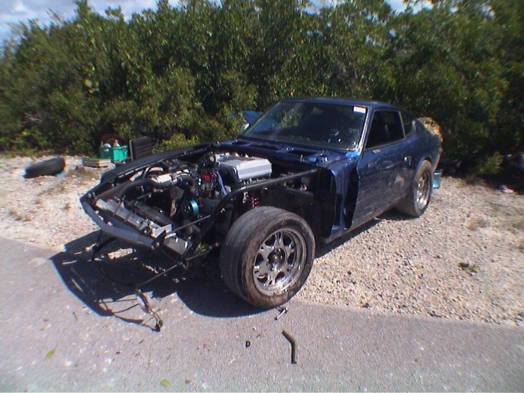
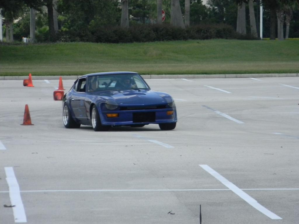
At this point, I have the Avon 23.0 x 10.5 x 15 cross ply slicks in hand and ready to install. They are getting mounted on my wheels monday. Then I will spend the early part of next week doing preliminary adjustment to the car (reduce camber, set ride height). I plan to install the new wheel and tire combo, remove the springs, and verify clearances for the anticipated range of suspension motion. The clearances found during this testing will determine the minimum camber that I will be able to run. Once I have found the preliminary settings, I am taking the car to a friend's shop where we will perform final alignment, corner balancing, and bump steer adjustment. This is scheduled for next Friday. One problem I may encounter is the inability to reduce camber sufficiently to make the tires happy. The Avons appear to be a little wider that the Hoosiers (at least while not mounted), so I may encounter clearance issues between the tires and fenders if I take out too much camber. With the Hoosiers, I was running -2.5 camber at the front and -2.0 at the rear. I am shooting for less than -1.5 at the front and less than -1.0 at the rear. Unfortunately, reducing camber on these cars reduces clearance between the fender and tire. We'll see how it goes. The car has a very stiff suspension (500 lb/in front springs and 425 lb/in rear springs) and I will be running between 6.5 to 7.0 degrees of caster at the front. The attached pictures shows how close the Hoosiers were (especially in the rear):